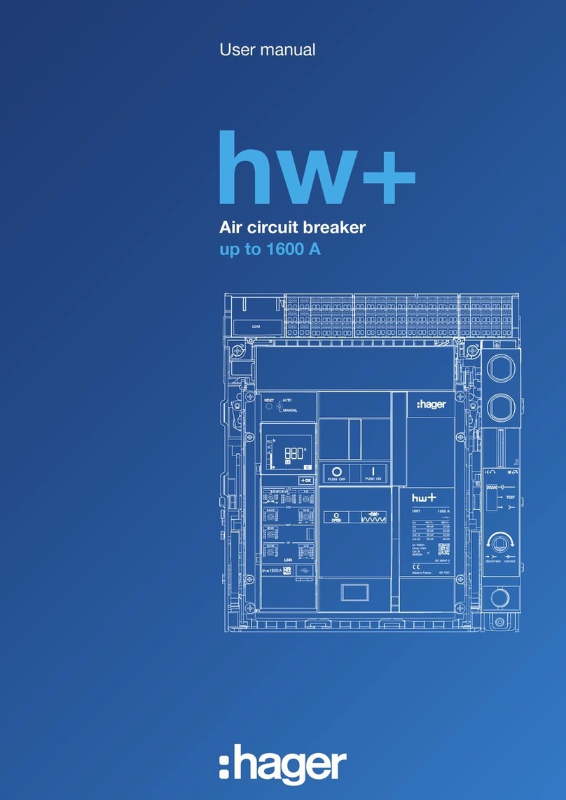
hager hw+ User manual

User manual
hw+
sentinel electronic trip units
RESET AUTO
MANUAL
In 160
0A
=
Ø5.8
COM

26LE007969A
01 About this manual 3
1.1 Safety instructions 3
1.2 Using this manual 5
02 sentinel electronic trip unit 6
2.1 Description 6
2.2 Display 8
2.3 LI trip unit 10
2.4 LSI trip unit 11
2.5 LSIG trip unit 12
2.6 Hager Power setup software 13
03 The types of protection device 15
3.1 Overview of protections 15
3.2 Long time delay protection against overcurrent 16
3.3 Short time delay protection against overcurrent 18
3.4 Instantaneous protection against overcurrent 20
3.5 Earth fault protection 21
3.6 Neutral protection 22
3.7 Zone Selective Interlocking function (ZSI) 23
04 Protection settings 26
4.1 Principle 26
4.2 Long time delay (LTD) protection setting 32
4.3 Short time delay (STD) protection setting 34
4.4 Instantaneous (INST) protection setting 36
4.5 Adjustment of the earth fault (GF) protection setting 37
4.6 Adjustment of the neutral (N) protection setting 39
4.7 Reviewing the settings 41
05 Commissioning the circuit breaker 44
06 Alarm management 45
6.1 PTA overload prealarm 45
6.2 Overload alarm 47
6.3 Trip alarm 48
6.4 System alarm 49
07 Maintenance indicator 52
08 Replacing the backup battery 53
09 Replacement of the rating plug of the electronic trip unit 60
Contents Page

36LE007969A
About this manual
1.1 Safety instructions
Warnings and instructions
This documentation contains safety advice which must be respected for your own safety and
to prevent property damage.
Safety advice relating to your own safety is identified by a safety warning symbol in the
documentation. Safety advice relating to damage to property is identified by "ATTENTION".
The safety warning symbols and the wording below are classified according to the risk level.
DANGER
DANGER indicates an imminent dangerous situation which, if not avoided, will result in
death or serious injuries.
ATTENTION
ATTENTION indicates a warning message relating to equipment damage.
ATTENTION also indicates important instructions for use and particularly relevant
information regarding the product, which must be respected to ensure eective and safe
use.
WARNING
WARNING indicates a potentially dangerous situation which, if not avoided, may result in
serious injuries or even death.
CAUTION
CAUTION indicates a potentially dangerous situation which, if not avoided, may result in
minor or moderate injuries.

46LE007969A
About this manual
1.1 Safety instructions
Qualified personnel
The product or the system described in this documentation must be installed, operated and
maintained by qualified personnel only. Hager Electro accepts no responsibility regarding the
consequences of this equipment being used by unqualified personnel.
Qualified personnel are those people who have the necessary skills and knowledge for
building, operating and installing electrical equipment, and who have received training
enabling them to identify and avoid the risks incurred.
Appropriate use of Hager products
Hager products are designed to be used only for the applications described in the catalogues
and in the technical documentation relating to them. If products and components from other
manufacturers are used, they must be recommended or approved by Hager.
Appropriate use of Hager products during transport, storage, installation, assembly,
commissioning, operation and maintenance is required to guarantee problem-free operation in
complete safety.
The permissible ambient conditions must be respected. The information contained in the
technical documentation must be respected.
Publication liability
The contents of this documentation have been reviewed in order to ensure that the information
is correct at the time of publication.
Hager cannot, however, guarantee the accuracy of all the information contained in this
documentation. Hager assumes no responsibility for printing errors and any damage they may
cause.
Hager reserves the right to make the necessary corrections and modifications to subsequent
versions.

56LE007969A
Purpose of the document.
This manual is designed to provide users, electricians, panel builders and maintenance
personnel with the technical information required for the commissioning and operation of hw+
circuit breakers with sentinel electronic trip units.
Field of application
This document applies to hw+ circuit breakers with electronic trip units.
Revisions
Version Date
6LE007969A September 2022
Documents to consult
Document Reference
User manual for hw+ air circuit breakers 6LE007331A
Installation manual for hw+ air circuit breakers 6LE007893A
hw+ user maintenance guide 6LE007897A
You can download these publications and other technical information from our website: www.
hager.com
Contact
Address Hager Electro SAS 132 Boulevard d’Europe
67215 Obernai France
Phone + 33 (0)3 88 49 50 50
Website www.hager.com
About this manual
1.2 Using this manual

66LE007969A
sentinel electronic trip unit
2.1 Description
hw+ air circuit breakers are equipped with a sentinel electronic trip unit on the front to protect
against overloads, short circuits and earth faults.
It has a display and dials to configure the protection settings and monitor correct operation.

76LE007969A
sentinel electronic trip unit
2.1 Description
The following characteristics are common
to all the versions of the sentinel electronic
trip units:
In 160
0A
=
1
2
3
4
5
6
3
7
1Display
2Button which can be used to :
- clear the alarm after the air circuit
breaker has tripped,
- navigate through the display screens.
3Adjustment dials of the sentinel electronic
trip unit.
4Rated current value In of the air circuit
breaker. This value is provided by the
rating plug installed on the electronic trip
unit.
5USB-C port to connect an external battery.
This USB-C port also allows connection
to a computer equipped with the Hager
Power setup commissioning software
(see Chapter 4.1 Principle).
6Backup battery powering the display after
electrical tripping.
This enables the display to signal
the tripping and its cause.
7Backup battery housing cover.
ATTENTION
To guarantee that the electronic trip unit functions well, it is recommended that a 24V
DC SELV external power supply be connected (recommended product reference Hager
HTG911H) to the TU terminal block.
Without this external power supply, the electronic trip unit requires the presence of a
minimum current of 120 A on one phase or 80 A per phase to provide its protection
functions.

86LE007969A
Description of the display
sentinel electronic trip units are equipped with a display that makes it easy to adjust and read
the causes of tripping of the hw+ circuit breakers.
AZE
6
7
8
9
1 2 3 4 5
R
1Overload indicator: displayed as soon as the current exceeds 105% of Ir.
2Error indicator: displayed when an error is detected.
3Maintenance indicator: displayed when a maintenance intervention is required.
4Text display area: displays the name of the protection parameter during adjustment or after a trip in
addition to the error codes of non-critical system alarms.
5Low or missing battery indicator: displayed if the electronic trip unit backup battery needs
changing or is not connected.
6Tripindicator: together with the digital display zone, the text display zone and the phase display,
enables the cause of the tripping to be precisely determined.
7Overload indicator: flashes as soon as the current exceeds 105% of Ir and is lit and steady above
112.5% Ir
8Overload pre-alarm indicator: warns of an imminent tripping risk.
9ReadyToProtect indicator: displayed when the electronic trip unit is operational
and ready to protect.
ANumerical display zone: used to display the values of the various settings
and what the tripping value was, using the following units.
A Ampere
 Peak current
S Second
I²t I²t curve
Also displays the codes of the critical system alarms.
ZPhase display: Neutral on the left / Phase L1 / Phase L2 / Phase L3.
EReference screen: shows the number of screens in the electronic trip unit
as well as its position in the display order.
RBargraph: used to view the currents read on the most highly loaded phase L1, L2 or L3 as a
percentage of the Ir setting.
sentinel electronic trip unit
2.2 Display

96LE007969A
In standby, the ReadyToProtect indicator flashes, indicating normal operation of the sentinel
electronic trip unit.
A short press of the button displays a 1st screen showing the highest current of the 3
phases flowing through the circuit breaker.
1
2
3
1
Current flowing through the circuit breaker in % of Ir.
2
Value in amps of the current flowing through the circuit breaker
on the most highly loaded phase.
3
Relevant phase.
sentinel electronic trip unit
2.2 Display

10 6LE007969A
The sentinel electronic trip unit is available in 3versions: LI, LSI and LSIG
LI sentinel trip unit
The LI sentinel trip unit is used to protect long cable lines where the rated fault current is
limited due to the impedance of the cable.
The dials are accessible from the front of the sentinel electronic trip unit, allowing precise
adjustment of the protection parameter settings. The protection adjusted in this way is
independent of the ambient temperature.
In 160
0A
=
1
2
3
1LTD Long time delay protection setting
2INST Instantaneous protection setting
3Neutral N protection setting
sentinel electronic trip unit
2.3 LI trip unit

116LE007969A
LSI sentinel trip unit
The LSI sentinel trip unit is used to protect cables lines and equipment requiring a wide variety
of protection settings.
The dials are accessible from the front of the sentinel electronic trip unit, allowing precise
adjustment of the protection parameter settings. The protection adjusted in this way is
independent of the ambient temperature.
In
1
60
0A
=
1
2
3
4
1LTD Long time delay protection setting
2STD Short time delay protection setting
3INST Instantaneous protection setting
4N neutral protection setting adjustment
sentinel electronic trip unit
2.4 LSI trip unit

12 6LE007969A
LSIG sentinel trip unit
The LSIG sentinel trip unit is used to protect cable lines and equipment for the case of a
coupling system to TN earth or protection against earth faults is required.
The dials are accessible from the front of the sentinel electronic trip unit, allowing precise
adjustment of the protection parameter settings. The protection adjusted in this way is
independent of the ambient temperature.
In
1
60
0A
=
1
2
3
4
5
1LTD Long time delay protection setting
2STD Short time delay protection setting
3INST Instantaneous protection setting
4GF earth fault protection setting
5N neutral protection setting adjustment
sentinel electronic trip unit
2.5 LSIG trip unit

136LE007969A
The Hager Power setup software has been designed for testing and commissioning hw+ trip
units.
Thanks to the commissioning menu, it is possible to specifically generate a commissioning
report proving that the protection settings comply with the short-circuit and selectivity
calculations. This requires the settings to be imported from the Hagercad software.
It oers a smart way of creating the protection settings. It also allows all the trip unit parameter
settings to be displayed and modified.
It is possible to perform a test of the hw+ circuit breakers tripping curve.
It also allows a forced electro-mechanical tripping of the circuit breakers to be performed.
It is very useful during the test phase when wiring the output contacts. It makes it possible to
force the opening or closing of the OAC and ZSI output contacts.
The result of the dierent tests can be entered into a test report that can be generated at any
time whether in the wiring workshop or during acceptance tests on site.
The functions of the Hager Power setup software can be accessed through five menus:
1Functional state of the circuit breaker, maintenance information and principal technical
characteristics.
2Three-stage procedure 1. Adjustment, 2. Test, 3.Tripping to commission the circuit breaker using
settings data imported from the Hagercad software. Allows a commissioning report to be generated.
3Access to all the parameter settings of the trip unit.
4Access to the tripping curve of the manual test, the forced electro-mechanical tripping and activation
of the output contacts available on the circuit breaker. Allows a test report to be generated.
5Access to event history.
Display of active alarms.
Operating counters panel.
3
4
5
sentinel electronic trip unit
2.6 Hager Power setup software
2
1

14 6LE007969A
Principal functions
• Display the functional state of the circuit breaker, maintenance information and principal
technical characteristics.
• Perform a commissioning or enter assisted settings by importing settings from Hagercad.
• Generate and print test reports and commissioning reports.
• Perform a manual test of the tripping curve of the hw+ circuit breakers.
• Perform a forced electro-mechanical tripping of the circuit breakers.
• Display and modify all the electronic trip unit parameter settings.
• Display alarms in progress.
• Download and export the electronic trip unit settings in a file in CSV format.
• Save the settings of a circuit breaker from within the Energy range to load them into one or
more similar circuit breakers.
• Force the opening or closing of the OAC and ZSI output contacts.
• Display the active alarms.
• View the event logs and export them in a file in CSV format.
• Display the status of the operating counters available (handling cycles, tripping operations...).
The Hager Power setup software is available on the Hager website for your country.
IT configuration required
Minimal Recommended
Operating
system Windows 10 x32 bits Windows 10 x64 bits
Memory 4 Gb RAM 8 Gb RAM
Disk space 50 Mb 50 Mb
Components
Microsoft .NET Framework 4.7.2
.NET Core Runtime 3.1.13
.NET Desktop Runtime 3.1.13
Microsoft web view 2 v1.0.818.14
Microsoft .NET Framework 4.7.2
or higher
.NET Core Runtime 3.1.13
or higher
.NET Desktop Runtime 3.1.13
or higher
Microsoft web view 2 v1.0.818.14
or higher
Resolution 1024x768 pixels 1280x1024 pixels
sentinel electronic trip unit
2.6 Hager Power setup software

156LE007969A
The types of protection device
3.1 List of protection devices
The sentinel electronic trip unit protects against overcurrent and earth faults for all types of
electrical distribution in accordance with the requirements of standards IEC 60947-1 and
60947-2.
Protection system
- Long delay against overcurrent - L: Overload protection
- Short delay against overcurrent - S: Protection against low current short circuits
- Instantaneous against overcurrent - I: Protection against high current short circuits
- earth fault - G: Phase-to-earth fault protection
- Neutral - N: Protection against overloads and short circuits which may flow through and
damage the neutral conductors.
I (A)
t (s) LS I
tr
lrlg lilsd
tsd
tg
l²t
l²t
LIr Long time delay protection threshold against overcurrent
tr Long time delay against overcurrent
S
Isd Short time delay protection threshold against overcurrent
tsd Short time delay against overcurrent
I²t ON/OFF Short time delay protection I²t curve against overcurrent
(activated/deactivated)
IIi Instantaneous protection threshold against overcurrent
G
Ig earth protection threshold
tg earth protection time delay
I²t ON/OFF earth protection I²t curve (activated/deactivated)
NNThreshold as % of the value of the neutral protection setting
(adjustment of the Ir and lsd thresholds)
Protection according to ANSI Code
LANSI 49
SANSI 50TD/51
IANSI 50
GANSI 50N TD/51N
In addition to Instantaneous protection, all sentinel electronic trip units include MCR protection
(Making Current Release). This guarantees immediate tripping of the hw+ circuit breakers in
cases of closing operation on a short-circuit.
Adjusting the protection
The protection settings can be modified using the dials and the display. All protection
functions are based on the root-mean-square value (RMS) of the current to take into account
the presence of current harmonics. The extensive choice of protection curve settings
facilitates coordination in terms of selectivity.

16 6LE007969A
The Long time delay protection is designed to protect the cables, the busbars and the busbar
sheaths from current overloads. It includes a thermal memory function that temporarily stores
the calculated thermal values so that the thermal eect of the cable heating remains available.
The phases and the neutral pole benefit independently from the Long time delay protection.
It can also be used to protect transformers or generators.
Long time delay protection curve
I (A)
t (s) L
tr
lr 6xlr
Long time protection
Long time delay parameters
LIr = Ir1 x Ir2 x In (A) Long time delay protection threshold against overcurrent
tr (s) Long time delay against overcurrent
Adjusting the lr current setting
The Long Time Delay protection tripping range is: 1.05 - 1.20 Ir.
The Ir current setting is adjusted using the 2 dials Ir1 and Ir2.
Rating (In) Pick up adjustment range Ir = Ir1 x Ir2 x In (A)
400 A 145.6 - 400 A
630 A 229.3 - 630 A
800 A 291.2 - 800 A
1000 A 364 - 1000 A
1250 A 455 - 1250 A
1600 A 582.4 - 1600 A
Adjusting the tr time delay
The tr time delay defines the trigger time of the long time delay protection for a current of 6 x
Ir.
The tr time delay is adjusted using the tr dial.
The types of protection device
3.2 Long time delay protection threshold against overcurrent

176LE007969A
tr adjustment range (s)
0.5 1.0 2.0 4.0 5.0 8.0 10.0 15.0 20.0 25.0
The trigger time tolerance for the long time delay protection is from 0 % to -20 %.
Example: for tr = 5s and I = 6 x Ir, the tripping time for the long time delay protection will be
between 3.98s and 5.03s.
Thermal image
Closing operation at a high load, successive starts of the motor or a fluctuating load, results
in current pulses similar to repetitive faults, which have a thermal eect on the conductors.
The cumulative eect of these successive current pulses will result in excessive heating of the
conductors.
Traditional Long time delay protection is not able to protect the conductors against repetitive
faults of this kind because the duration of each detected overload is too short to cause
eective tripping.
Thanks to its thermal memory and imaging function, the sentinel electronic trip unit memorizes
and integrates the thermal eects of the detected overloads whatever the current value. These
functions are guaranteed even if the trip unit is not powered by an external power supply. This
reduces the associated Long time delay time to cause eective tripping before the conductors
overheat.
The thermal memory and image function of the sentinel trip unit provides optimal protection of
the cables and busbars against overheating.
a)
c)
b)
I
1) t
2)
Tripping with and without thermal imaging
Key:
a) Calculation with thermal memory
b) Calculation without thermal memory
c) Current in the load
1) Tripping case a)
2) Tripping case b)
The example above clearly shows that the trip unit a) with thermal memory trips earlier and
thus protects the conductors better than trip unit b) without thermal memory.
Note: The thermal memory and imaging function of the sentinel electronic trip units cannot be
deactivated.
The types of protection device
3.2 Long time delay protection against overcurrent

18 6LE007969A
Short time delay protection is designed to protect against short circuits.
Short time delay protection curve
I (A)
t (s) S
lsd
tsd
l²t
Short time delay protection
Short time delay parameters
S
Isd (x Ir) Short time delay protection threshold against overcurrent
tsd (s) Short time delay against overcurrent
I²t (ON/OFF) Short time delay protection I²t curve against overcurrent
Adjusting the lsd pick-up setting
The lsd pick-up is adjusted using the lsd dial.
Isd pick-up adjustment range (x Ir)
OFF 1.0 1.5 2.0 2.5 3.0 4.0 6.0 8.0 10.0
When the Isd setting is OFF, the short time delay protection is deactivated.
The lsd tripping tolerance threshold for short time delay protection is ±10%.
Adjusting the tsd time delay
The tsd time delay is adjusted using the tsd dial.
tsd adjustment range (s) 0.05 0.10 0.20 0.40 0.60
Non-tripping time (s) 0.025 0.075 0.175 0.375 0.575
Maximum tripping time (s) 0.1 0.15 0.25 0.45 0.65
Maximum breaking time (s) 0.12 0.17 0.27 0.47 0.67
The types of protection device
3.3 Short time delay protection against overcurrent

196LE007969A
An inverse time function I²t=K can be activated or deactivated when adjusting the short time
delay.
This I²t function makes it possible to improve selectivity with downstream devices. It is
activated from the Isd pick-up and functions up to 10xIr.
I (A)
t (s)
10xlr
tsd
l²t
lr lsd
Short time delay protection I²t
The types of protection device
3.3 Short time delay protection against overcurrent

20 6LE007969A
Instantaneous protection is designed to protect against high short circuit currents. This
protection is time-independent.
Instantaneous protection curve
I (A)
t (s) I
li
Instantaneous protection
Instantaneous protection parameters
IIi (x In) Instantaneous protection threshold against overcurrent
Adjusting the Ii pick-up setting
The Ii pick-up is adjusted using the li dial.
li pick-up adjustment range (x In)
OFF 1.5 2.0 3.0 4.0 6.0 8.0 10.0 12.0 15.0
The li pick-up tolerance for instantaneous protection is ±10%.
Tripping time
Instantaneous protection has no adjustable time delay.
The non-tripping time is 20 ms.
The maximum breaking time is 70 ms.
The types of protection device
3.4 Instantaneous protection against overcurrent
Other manuals for hw+
2
Table of contents
Other hager Circuit Breaker manuals

hager
hager TYFS130 User manual

hager
hager h Series User manual

hager
hager CDC740H User manual

hager
hager CE480U User manual

hager
hager TR521 User manual

hager
hager ZY9NK User manual

hager
hager K14 Series User manual

hager
hager TR 304A Installation instructions

hager
hager RCCB 25-63A User manual

hager
hager h 160 H User manual

hager
hager H125 User manual

hager
hager VE24AH User manual

hager
hager h3 x250 User manual

hager
hager XEVS020 Operating and safety instructions
hager
hager CDB D Series User manual

hager
hager CEA263U User manual

hager
hager SPN900 User manual

hager
hager h3+ Use and care manual

hager
hager HX 830 User manual

hager
hager h3+ HTP610H User manual