Hausted EPC500ST User manual

EPC500ST-INS-LAB-REVA21
EPC500ST PROCEDURE CHAIR
OPERATING MANUAL
READ THIS MANUAL BEFORE OPERATING YOUR EPC500ST PROCEDURE CHAIR.
SAVE THIS MANUAL FOR FUTURE USE.
THE MOST CURRENT VERSION OF THIS MANUAL CAN BE FOUND ONLINE AT
WWW.HAUSTED.COM.

EPC500ST-INS-LAB-RevA21 2
CONTENTS
INTRODUCTION — A WORD FROM GF HEALTH PRODUCTS, INC. ................................................................................................... 4
INDICATIONS FOR USE ......................................................................................................................................................... 4
SERVICE INFORMATION........................................................................................................................................................ 4
ADVISORY............................................................................................................................................................................... 4
1 LIST OF WARNINGS AND CAUTIONS........................................................................................................................................... 5
SIGNIFICANCE OF SAFETY STATEMENTS .................................................................................................................................. 5
DANGER / WARNING / CAUTION / NOTICE SUMMARY ...................................................................................................... 5
WARNING: TO REDUCE THE RISK OF BURNS, FIRE, ELECTRIC SHOCK, OR PERSONAL INJURY ................ 5
WARNING — CAUTIONS AND PROPER OPERATION ................................................................................................................. 6
ELECTROMAGNETIC COMPATIBILITY (EMC) INFORMATION.................................................................................................... 7
2 UNCRATING INSTRUCTIONS......................................................................................................................................................... 8
IMPORTANT — REPORT ANY SHIPPING DAMAGE IMMEDIATELY............................................................................................ 8
NOTICE — POSSIBLE EQUIPMENT DAMAGE ............................................................................................................................. 8
WARNING — PERSONAL INJURY HAZARD................................................................................................................................. 8
ENVIRONMENTAL CONDITIONS .................................................................................................................................................. 8
OPERATING ............................................................................................................................................................................ 8
STORAGE AND TRANSPORT................................................................................................................................................ 8
UNPACKING INSTRUCTIONS ........................................................................................................................................................ 8
3 OPERATING INSTRUCTIONS......................................................................................................................................................... 9
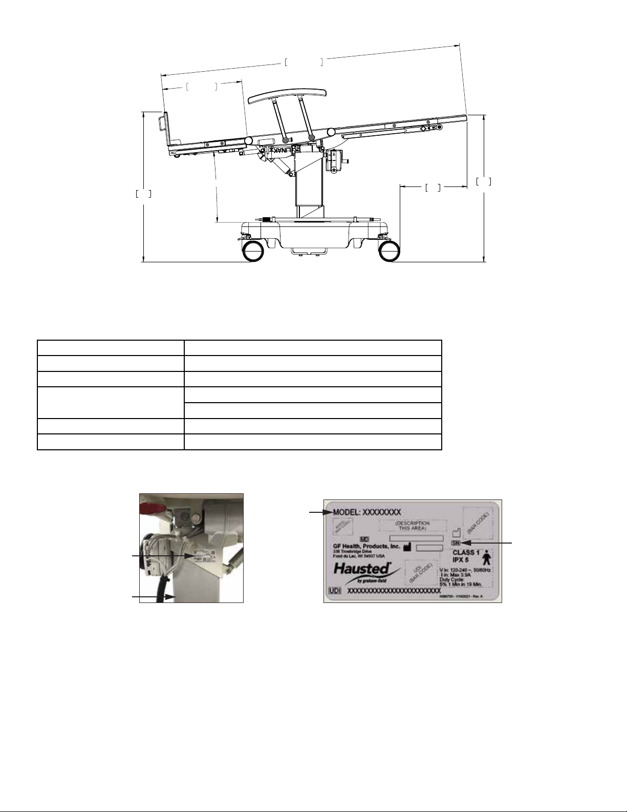
3.1 EPC500ST SPECIFICATIONS................................................................................................................................................. 9
ELECTRICAL SPECIFICATIONS.......................................................................................................................................... 10
IDENTIFICATION LABEL ...................................................................................................................................................... 10
3.2 FEATURES, WARNINGS AND PROPER OPERATION OPERATING INSTRUCTIONS ..................................................... 11
WARNINGS — CAUTIONS AND PROPER OPERATION (SEE DIAGRAM ON FOLLOWING PAGE) ............................... 11
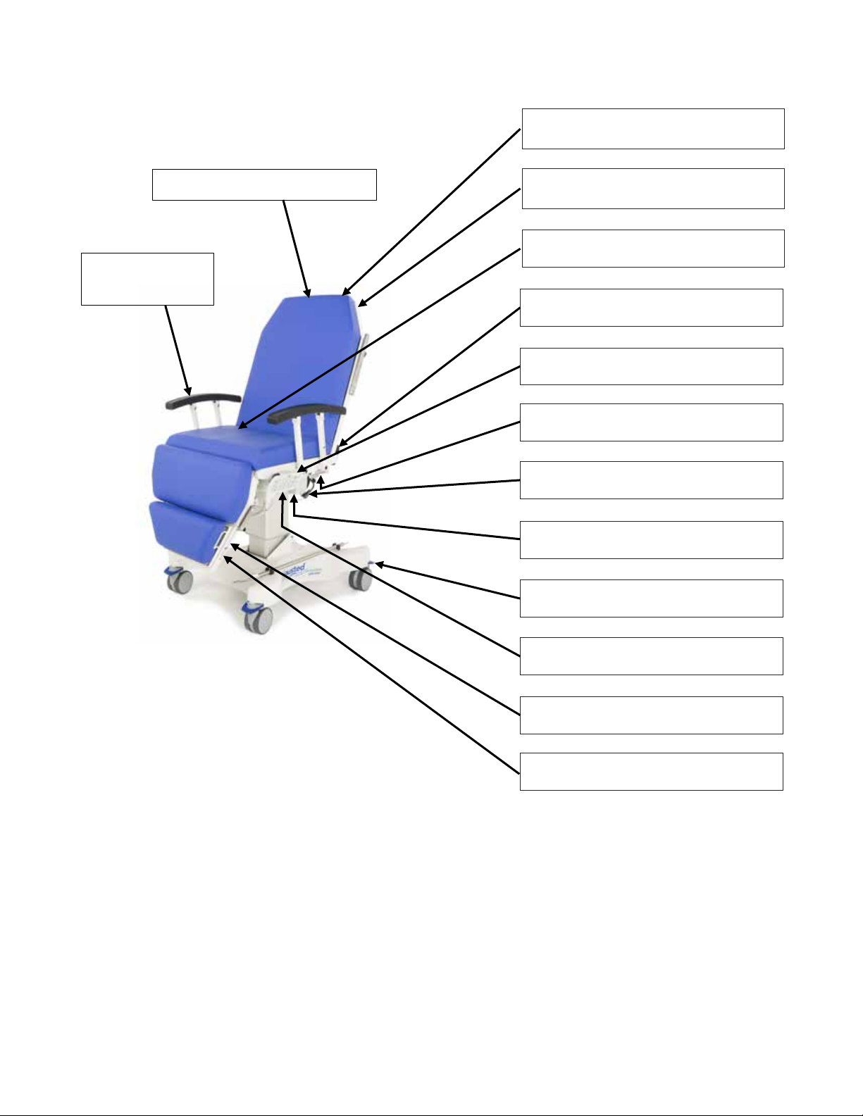
FEATURES (SHOWN IN ILLUSTRATION) ........................................................................................................................... 12
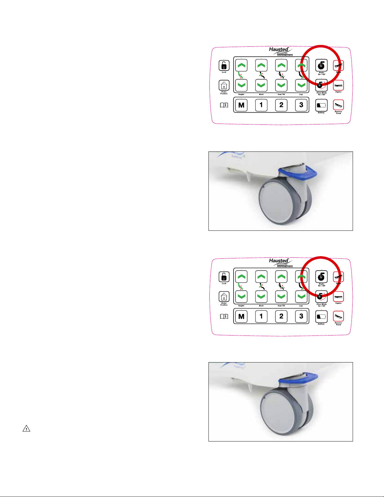
3.3 BRAKING AND STEERING OPERATION WITH SMART CASTER TECHNOLOGY .......................................................... 13
3.3.1 APPLYING THE BRAKES.......................................................................................................................................... 13
3.3.2 UNLOCKING THE BRAKES...................................................................................................................................... 13
3.3.3
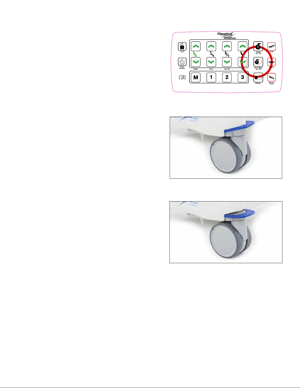
ACTIVATING ADVANCED STEER MODE — PENDANT ............................................................................................. 14
3.3.4
ACTIVATING ADVANCED STEER MODE – MANUALLY ............................................................................................ 14
3.3.5 DEACTIVATING ADVANCED STEER MODE — PENDANT..................................................................................... 15
3.3.6 DEACTIVATING ADVANCED STEER MODE – MANUALLY.................................................................................... 15
CASTER PEDAL POSITIONS.................................................................................................................................... 15
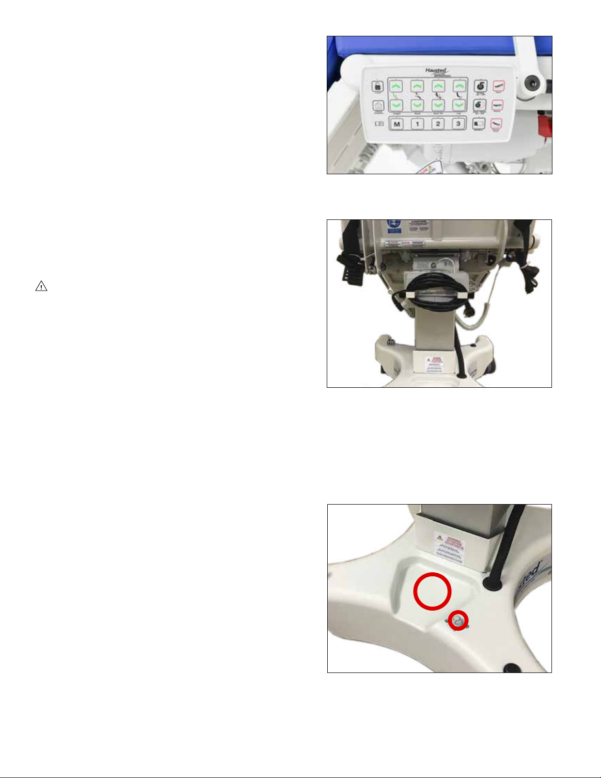
3.4 ELECTRIC CONTROL LOCATIONS..................................................................................................................................... 16
3.4.1 PENDANT CONTROL STORAGE LOCATION.......................................................................................................... 16
3.4.2 PLUG LOCATION....................................................................................................................................................... 16
3.4.3 LOW BATTERY ALARM ............................................................................................................................................ 16
3.4.4 FOOT CONTROL ....................................................................................................................................................... 16
3.5 HEIGHT AND PATIENT SURFACE ADJUSTMENT.............................................................................................................. 17
3.5.1 LOCK / UNLOCK (BUTTON 1) .................................................................................................................................. 17
3.5.2 HEIGHT (HI / LO) (BUTTONS 2 AND 9) .................................................................................................................... 17
3.5.3 BACK SECTION UP / DOWN (BUTTONS 3 AND 10)............................................................................................... 18
3.5.4 SEAT TILT UP / DOWN (BUTTONS 4 AND 11)......................................................................................................... 18
3.5.5 LEG UP / DOWN (BUTTONS 5 AND 12)................................................................................................................... 19
3.5.6 BRAKE AND STEER MODE OPERATION (BUTTONS 6 AND 13) .......................................................................... 19
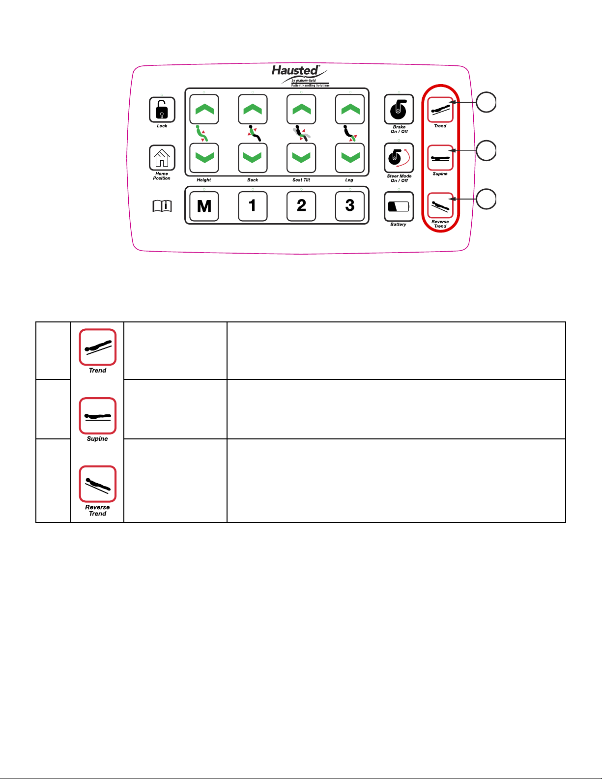
3.5.7 TRENDELENBURG, SUPINE AND REVERSE TRENDELENBURG POSITIONS (BUTTONS 7, 14 AND 20)........ 20
3.5.8 MEMORY AND PRESET FUNCTIONS (BUTTONS 15-18) ....................................................................................... 21
3.5.9 BATTERY (BUTTON 19) ............................................................................................................................................ 22
3.5.10 HOME (BUTTON 8).................................................................................................................................................... 22
3.5.11 EMERGENCY DROP BACK ...................................................................................................................................... 22
3.6 ADJUSTABLE FOOTREST ................................................................................................................................................... 23
3.6.1 REPOSITIONING THE FOOTREST........................................................................................................................... 23

EPC500ST-INS-LAB-RevA21 3
3.7 ADJUSTABLE LEG EXTENSION ......................................................................................................................................... 24
3.7.1 REPOSITIONING THE MOTORIZED LEG EXTENSION........................................................................................... 24
EXTENDING THE MOTORIZED LEG EXTENSION .................................................................................................. 24
RETRACTING THE MOTORIZED LEG EXTENSION................................................................................................ 24
SAFETY LIMITS ......................................................................................................................................................... 24
OPERATION WHILE LEG EXTENSION IS EXTENDED (ANY DISTANCE) ............................................................ 24
OPERATION WHILE LEG EXTENSION IS RETRACTED......................................................................................... 25
3.8 PIVOTING RAILS .................................................................................................................................................................. 26
3.8.1 REPOSITIONING THE RAIL...................................................................................................................................... 26
LOWERING THE PIVOTING RAIL............................................................................................................................. 26
RAISING THE PIVOTING RAIL ................................................................................................................................. 26
3.9 PUSH HANDLES ................................................................................................................................................................... 27
3.9.1 OPERATING THE PUSH HANDLES ......................................................................................................................... 27
ROTATING AND POSITIONING THE HAND GRIPS................................................................................................. 27
OPERATING THE PUSH HANDLES WITH THE BACK IN RAISED POSITION ...................................................... 27
OPERATING THE PUSH HANDLES WITH THE BACK IN LOWERED POSITION ................................................. 27
3.10 COMMON OPTIONAL ACCESSORIES ................................................................................................................................ 28
3.10.1 INSTALLING THE IV ROD ......................................................................................................................................... 28
3.10.2 USING SAFETY STRAPS .......................................................................................................................................... 28
4 TROUBLESHOOTING GUIDE ....................................................................................................................................................... 29
4.1 CONTROL BOX..................................................................................................................................................................... 31
4.2 BATTERY REPLACEMENT................................................................................................................................................... 31
5 PREVENTIVE MAINTENANCE FOR THE USER.......................................................................................................................... 33
6 OPTIONAL ACCESSORIES .......................................................................................................................................................... 34
7 GF HEALTH PRODUCTS, INC. LIMITED WARRANTY FOR HAUSTED BRAND STRETCHERS AND CHAIRS ..................... 35
8 DISPOSAL AND KEY TO SYMBOLS............................................................................................................................................ 36
DISPOSAL...................................................................................................................................................................................... 36
KEY TO SYMBOLS........................................................................................................................................................................ 36
9 APPENDIX...................................................................................................................................................................................... 37
9.1 GUIDANCEANDMANUFACTURER’SDECLARATION—ELECTROMAGNETICEMISSIONS....................................... 37
9.2 ENCLOSURE PORT 1........................................................................................................................................................... 37
9.3 ENCLOSURE PORT IMMUNITY TO RF WIRELESS COMMUNICATIONS EQUIPMENT 1................................................ 38
9.4 INPUT AC POWER PORT 1.................................................................................................................................................. 39
9.5 PATIENT COUPLING PORT 1............................................................................................................................................... 40
9.6 SIGNAL INPUT / OUTPUT PARTS PORT 1.......................................................................................................................... 41
9.7 RECOMMENDED SEPARATION DISTANCES BETWEEN PORTABLE AND MOBILE RF COMMUNICATIONS
EQUIPMENT AND HAUSTED EPC500ST PROCEDURE CHAIR 1..................................................................................... 42
9.8 NOTES TO SECTIONS 9.2 - 9.7............................................................................................................................................42
9.9 CERTIFICATIONS.................................................................................................................................................................. 42
10 INDEX ............................................................................................................................................................................................. 43
COPYING PROHIBITED
This manual is protected by Federal Copyright Law, which provides for damages of up to USD
$20,000, as well as criminal nes and imprisonment, for unauthorized copying.

EPC500ST-INS-LAB-RevA21 4
INTRODUCTION — A WORD FROM GF HEALTH PRODUCTS, INC.
This manual contains important information on proper use and maintenance of the Hausted
EPC500ST Procedure Chair. All personnel involved in the use and maintenance of this equipment
must carefully review and comply with the warnings, cautions and instructions contained in this
manual. These instructions are important to protect the health and safety of personnel operating
the model EPC500ST Procedure Chair, and should be retained in a conveniently accessible area for
quick reference.
Complete instructions for uncrating and putting your new equipment in service, as well as
equipment drawings, have been furnished. If missing, contact GF Health Products, Inc. for
replacement copies, giving the serial number and model number of the unit.
GF Health Products, Inc. carries a complete line of accessories for use with these chairs; your
representative will gladly review these with you.
Indications for Use
The Hausted EPC500ST Procedure Chair is intended for use in patient treatment, transport or
recovery. It has a radiolucent back for X-ray imaging capabilities of 20" x 25 1/2" (50.8 cm x 64.8 cm)
width x height with a range of 0° to 90°. The product has an expected service life of ve years.
The chair’s back can be positioned from sitting to supine. Height positioning, as well as back,
seat, and leg section adjustment, is electric / battery powered and is activated with a pendant.
The motorized leg extension is controlled by a switch underneath the footrest end. Four
advanced-steer casters allow maximum mobility and maneuverability, with control through either
pendant or manual operation.
Service Information
A thorough preventive maintenance program is essential to safe and proper unit operation. This
manual contains maintenance schedules and procedures which should be followed for satisfactory
equipment performance.
We encourage you to contact GF Health Products, Inc. with maintenance concerns.
Advisory
A listing of the safety precautions to be observed when operating and servicing this equipment
can be found in Section 1 of this manual. Do not operate or service the equipment until you
have become familiar with this information. Any alteration of this equipment not authorized or
performed by GF Health Products, Inc., could affect its operation, will void the warranty, could
violate national, state, and local regulations, and could jeopardize your insurance coverage.
Info: Column 1 below applies only if product was purchased outside the U.S.
EC REP
EC Authorized
Representative:
CEpartner4U BV
ESDOORNLAAN 13
3951DB MAARN
The Netherlands
+31(0)6 516 536 26
Manufactured by:
GF Health Products, Inc.
One Graham-Field Way
Atlanta GA 30340-3140
1.770.368.4700 Main
1.770.368.2386 Fax
www.grahameld.com
www.Hausted.com
Info: The base language of this document is ENGLISH. Any translations must be made from
the base language document.
Class 1 Equipment
Type B Equipment
Equipment not suitable for use
inthepresenceofammable
anesthetic mixture with air or
oxygen or nitrous oxide
.
IPX5 (Water-resistant)
Not suitable for continuous
operation (Duty Cycle:
5% 1 Min in 19 Min on Battery;
10% 2 Min in 18 Min on Mains
Power)

EPC500ST-INS-LAB-RevA21 5
1 LIST OF WARNINGS AND CAUTIONS
IMPORTANT: Before using the Hausted EPC500ST Procedure Chair, please read and adhere
to the following safety precautions and warnings. Failure to do so could result in serious
personal injury or damage to the EPC500ST Procedure Chair.
Always consult your healthcare professional to determine safe methods most suitable for your
individual abilities. Protect yourself, your attendant, and the Hausted EPC500ST Procedure Chair
by having it serviced regularly. If you experience any malfunction, contact your Graham-Field
authorized distributor immediately, as a hazardous condition could result, causing personal injury
or damage to the Hausted EPC500ST Procedure Chair.
Periodic inspection, adjustment and replacement of worn parts are necessary to provide years of
excellent service. Maintenance MUST be performed by qualied personnel ONLY.
SAVE THESE INSTRUCTIONS.
SIGNIFICANCE OF SAFETY STATEMENTS
Please note the following special statements, used throughout this manual, and their signicance:
DANGER: Indicates a potential hazard situation or unsafe practice that, if not avoided, will
result in death or serious personal injury.
WARNING: Indicates a potential hazard situation or unsafe practice that, if not avoided,
could result in death or serious personal injury.
CAUTION: Indicates a potential hazard situation or unsafe practice that, if not avoided,
could result in minor or moderate personal injury.
sNOTICE: Indicates a potential hazard situation or unsafe practice that, if not avoided, could
result in product or property damage.
Info: Provides application recommendations or other useful information to ensure that you get
the most from your product.
DANGER / WARNING / CAUTION / NOTICE Summary
The following is a listing of the safety precautions which must be observed when operating and
servicing this equipment. These precautions are repeated (in whole or in part), where applicable,
throughout the manual.
WARNING: To Reduce the Risk of Burns, Fire, Electric Shock, or Personal Injury
DANGER: SHOCK HAZARD — To reduce the risk of electric shock, unit is to be serviced by
qualiedpersonnelonly.
DANGER: SHOCK HAZARD — To avoid risk of electric shock, this equipment must only be
connected to a supply mains with protective earth.
WARNING:LACERATIONHAZARD—Whencuttingbandsalwaysuseatoolspecically
designed for that purpose. This will help to avoid personal injuries frequently incurred
when bands are cut and tension released.

EPC500ST-INS-LAB-RevA21 6
WARNING — CAUTIONS AND PROPER OPERATION
WARNING: The EPC500ST Procedure Chair has a maximum patient weight capacity 600 lb
(272 kg), EVENLY DISTRIBUTED.
WARNING: The EPC500ST Procedure Chair has a maximum weight, including equipment
weight and maximum patient weight, of 865 lb (393 kg).
WARNING: The chair is not intended to replace a stretcher or gurney.
WARNING: The chair has warning labels on both the head and foot end stating: Do not sit
on end — as tipping may occur.
WARNING: Do not stand on footrest — tipping may occur.
WARNING: When not in use, do not leave the chair in a recline position.
WARNING: When patient is seated in the chair, ensure the side rails are up and the patient
is secured with patient safety straps.
WARNING: Patient entry, egress and transfer from the chair should always be from the
center side rail location with the side rail in the down position and the brakes locked.
WARNING: At no time should the patient be permitted to enter or exit from the ends of the
chair when in partial or total recline position.
WARNING: Ensure the brakes are locked when the patient is not being transported.
WARNING: The pendant has a warning label on it stating: Place pendant in holder when
not in use — keep cord clear of moving parts.
WARNING: EPC500ST Procedure Chair is equipped with a built in battery back-up system:
nevertheless, the unit should remain plugged into wall receptacle during normal use. The
battery back-up is recommended for transport and emergency only.
WARNING: The back quick drop handle is intended to be used during emergency
situations only.
WARNING: To turn electric controls on, plug into wall receptacle. To turn off, remove plug
from wall receptacle. The electric powered chairs do not have a separate on / off switch.
WARNING: The chair has a warning label located above the control box cover stating:
Toreducetheriskofelectricalshockdonotremovethecover.Servicebyqualied
personnel only.
WARNING: Always disconnect the power source when troubleshooting or servicing the
chair.
WARNING: Steam cleaning and pressure washing of chair is not recommended and can
void warranty.
WARNING: The chair has a warning label indicating a pinch point located on both side
rails (pinch point between seat section and side rail), on foot section (pinch point between
xedandextendedfootsections),andonbackpushhandles.
WARNING: Cables can become pinched. Keep cables away from column.
WARNING: Lowering chair in supine position onto an object may cause tipping and
personal injury.

EPC500ST-INS-LAB-RevA21 7
WARNING: This product can expose you to chemicals including Di(2-ethylhexyl)phthalate
(DEHP) which is known to the State of California to cause cancer or birth defects or other
reproductive harm. For more information go to www.P65Warnings.ca.gov/furniture.
CAUTION: Stow away power cord when not in use to prevent injury or damage.
ELECTROMAGNETIC COMPATIBILITY (EMC) INFORMATION
WARNING: Medical Electrical Equipment needs special precautions regarding EMC and
needs to be installed and put into service according to the EMC information provided in this
manual.
WARNING:ElectronicequipmentmaybeinuencedbyRadioFrequency(RFI).Caution
should be exercised with regard to the use of portable communications in the area around
such equipment. Portable RF communications equipment (including peripherals such as
antenna cables and external antennas) should be used no closer than 30 cm (12 inches)
toanypartoftheHaustedequipmentincludingspeciedHaustedequipmentcables.
Degradation of the performance of the Hausted equipment could result.
WARNING: If RFI causes erratic behavior, unplug the electric Hausted equipment
immediately. Leave unplugged while transmission is in progress.
WARNING:Theuseofaccessories,transducers,andcablesotherthanthosespeciedby
the manufacturer may result in increased emissions or decreased immunity of the Hausted
equipment. GF cables and accessories include motor cables, mains cable, pendant cables,
and back up battery and cable.
WARNING: This equipment should not be used adjacent to or stacked with other
equipment. If adjacent or stacked use with other equipment is necessary, this Hausted
equipment and the other equipment should be observed to verify that they are operating
normally.
WARNING: The EMISSIONS characteristics of this equipment make it suitable for use in
industrial areas and hospitals (CISPR 11 class A). If it is used in a residential environment
(for which CISPR 11 class B is usually required) this equipment might not offer adequate
protection to radio frequency communication services. The user might need to take
mitigation measures, such as relocating or reorienting the equipment.

EPC500ST-INS-LAB-RevA21 8
2 UNCRATING INSTRUCTIONS
IMPORTANT — REPORT ANY SHIPPING DAMAGE IMMEDIATELY
WARNING: Inform shipper of any damages — leave carton intact. Leave equipment in the
receiving area until inspection is complete.
NOTICE — POSSIBLE EQUIPMENT DAMAGE
sNOTICE: The crate contains fragile, expensive medical equipment. Uncrate and handle
carefully.Ifafteruncratingtheequipmentyoundanydamage(nomatterhowslight),
report the damage to GF Health Products, Inc.
WARNING — PERSONAL INJURY HAZARD
WARNING:Whencuttingbands,alwaysusetoolspecicallydesignedforthatpurpose.
This will help avoid personal injuries possibly incurred when bands are cut and tension is
released.
ENVIRONMENTAL CONDITIONS
Operating
Temperature 5°C to 40°C
Relative Humidity 20% to 90% @ 30°C
Atmospheric Pressure 700 to 1060 hPa
Storage and Transport
Temperature -10°C to 50°C
Relative Humidity 20% to 90% @ 30°C
Atmospheric Pressure 700 to 1060 hPa
IMPORTANT: Follow each step in the order shown in these instructions.
UNPACKING INSTRUCTIONS
Your Hausted equipment has been carefully packed at our manufacturing plant to ensure safe
shipment to your medical facility. There are several procedures you must follow to put your new
equipment in service. These procedures only take a few minutes to complete and all are required
to ensure proper operation of the equipment.
1. Cut the two bands around the shipping carton.
2. Remove the top cap of the carton and remove the two box side panels.
3. Remove the equipment from the carton.
4. Check to see if all features of the equipment work properly. If all features work, advance
to step 5. If any of the features do not work properly, call GF Health Products, Inc. at
1.770.368.4700 if purchased within the U.S., or the authorized distributor from whom you
purchased the unit if outside the U.S.
Info: Plug the unit into a wall socket prior to checking any electric features. The battery will
reach full charge after approximately 10 hours.
5. Clean the equipment using mild detergent to remove any dirt accumulated during shipment,
and place the equipment into service.

EPC500ST-INS-LAB-RevA21 9
3 OPERATING INSTRUCTIONS
3.1 EPC500ST SPECIFICATIONS
Info: All dimensions are specied in [millimeters] and inches. Unless otherwise noted, all
dimensions are ± [10 mm] .375 in. Dual dimensions are minimum (left) and maximum (right)
when shown in chair position, and opposite — maximum (left) and minimum (right) when
shown in Trendelenburg position.
90°
470
18.5
(FULLY RETRACTED)
65°
5°
106°
495 / 991
19.5 / 39.0
38
1.5
1308
51.5
191 / 686
7.5 / 27.0
DO NOT USE
LEG EXTENSION
IN CHAIR MODE
Home Position - Side View
(Back Range
From Horizontal
0
to 90
)
546 / 1042
21.5 / 41.0
674
26.5
699
27.5
799
31.5
629
24.75
242
9.5
1270 / 1765
50.0 / 69.5
Home position, side view Home position, front view
15°
1994 / 1791
78.5 / 70.5
673 / 470
26.5 / 18.5
546
21.5
381
15.0
1207
47.5
Trendelenburg position, side view

EPC500ST-INS-LAB-RevA21 10
1994 / 1791
78.5 / 70.5
673 / 470
26.5 / 18.5
6°
876
34.5
394
15.5
889
35.0
Reverse Trendelenburg position, side view
ElectricalSpecications
ProductClassication 1
Input Voltage 100-240V~ 50/60 Hz
Amperage Maximum 4.5A
Duty Cycle 5% 1 min. in 19 min. on Battery
10% 2 min. in 18 min. on Mains Power
IP Rating IPX5
Grounding Protection Type B
IdenticationLabel
identification label
column
Identification label location Identification label example
model
serial number
The chair identication label identies the chair serial number and model, essential information
when ordering replacement parts or claiming parts under warranty. The identication label, shown
above, is beneath the seat on patient right, afxed to the column. Have this information ready
when calling our Customer Service or Technical Support staff at 1.770.368.4700, or your authorized
distributor if purchased outside the U.S.; it will allow us to better assist you and quickly answer
your questions and concerns.

EPC500ST-INS-LAB-RevA21 11
3.2 FEATURES, WARNINGS AND PROPER OPERATION OPERATING INSTRUCTIONS
WARNINGS — CAUTIONS AND PROPER OPERATION (See Diagram on following page)
A. WARNING: The EPC500ST Procedure Chair has a maximum patient weight capacity of
272 kg (600 lb), EVENLY DISTRIBUTED.
WARNING: The EPC500ST Procedure Chair has a maximum weight capacity, including
equipment weight and patient weight, of 393 kg (865 lb).
B. WARNING: The chair is not intended to replace a stretcher or gurney.
C. WARNING: The chair has warning labels on both the head and foot end stating: Do not
sit on end - as tipping may occur.
D. WARNING: Do not stand on footrest — tipping may occur.
E. WARNING: When not in use, do not leave the chair in a recline position.
F. WARNING: When patient is seated in the chair, ensure the side rails are up and the
patient is secured with patient safety straps.
G. WARNING: Patient entry, egress and transfer from the chair should always be from the
center side rail location with the side rail in the down position and the brakes locked.
H. WARNING: At no time should the patient be permitted to enter or exit from the ends of
the chair when in partial or total recline position.
I. WARNING: Ensure the brakes are locked when the patient is not being transported.
J. WARNING: The pendant has a warning label on it stating: Place pendant in holder when
not in use — keep cord clear of moving parts.
K. WARNING: All electric-powered chairs are equipped with a built in battery back-up
system, but it is recommended that the unit remain plugged in wall receptacle during
normal use. The battery back-up is recommended for transport and emergency only.
L. WARNING: The back quick drop handle is intended to be used during emergency
situations only.
M. WARNING: To turn electric controls on, plug into wall receptacle. To turn off, remove
plug from wall receptacle. The electric powered chairs do not have a separate on / off
switch.
N. WARNING: The chair has a warning label located above the control box cover stating:
Toreducetheriskofelectricalshockdonotremovethecover.Servicebyqualied
personnel only.
O. WARNING: Always disconnect the power source whenever servicing any electric
powered chair.
P. WARNING: The chair has a warning label indicating a pinch point located on both side
rails (pinch point between seat section and side rail), on foot section (pinch point between
xedandextendedfootsections),andonbackpushhandles.
Q. WARNING: Cables can become pinched. Keep cables away from column.
R. CAUTION: Stow away power cord when not in use to prevent injury or damage.

EPC500ST-INS-LAB-RevA21 12
Features (Shown in Illustration)
PIVOTING RAIL
See WARNING F
PATIENT COMFORT CUSHIONS
TOP TUBE WARNING LABEL
See WARNINGS C & H
BACK OF CHAIR WARNING LABEL
See WARNINGS A & P
PATIENT ENTRY
See WARNINGS G & H
SAFETY STRAP
See WARNING F
RAIL LATCH
See WARNINGS F & P
EMERGENCY QUICK DROP HANDLE
See WARNING L
POWER CORD
See WARNINGS K, N & Q, CAUTION R
ELECTRIC CONTROL BOX CIRCUITRY
See WARNINGS M — O
BRAKE PEDAL
See WARNINGS G & I
PATIENT PENDANT WARNING LABEL
See WARNING J
FOOT SECTION TUBE WARNING LABEL
See WARNINGS C & H
ADJUSTABLE FOOTREST WARNING LABEL
See WARNINGS D & P

EPC500ST-INS-LAB-RevA21 13
3.3 BRAKING AND STEERING
OPERATION WITH SMART CASTER
TECHNOLOGY
3.3.1 Applying the Brakes
To apply the four wheel central braking
system with the pendant, press the pendant
Brake On / Off button; the LED above the
button then illuminates green (Figure 3.3-1),
and the blue caster pedals on all four corners
of the chair automatically lower to lock
(Figure 3.3-2), and all four caster wheels will
then be locked from swiveling and rotating.
Info: To prevent unintended movement, the
brakes engage automatically after the unit
has been stationary for 30 seconds.
To apply the four-wheel central braking
system manually, gently depress the blue
caster pedal at any of the four corners of the
chair until the pedal stops (Figure 3.3-2). The
remaining three pedals will then automatically
lower to lock (Figure 3.3-2), and all four caster
wheels will then be locked from swiveling and
rotating.
sNOTICE: DO NOT apply excessive force
to pedal when manually applying brakes.
3.3.2 Unlocking the Brakes
To unlock the brakes with the pendant, press
the pendant Brake On / Off button; the LED
above the button then goes out (Figure 3.3-3),
the blue caster pedals on all four corners of
the chair will then automatically rise to unlock
(Figure 3.3-4), and all four caster wheels will
then rotate and swivel freely.
To unlock the brakes manually, gently lift the
blue caster pedal at any of the four corners
of the chair until the pedal is in a horizontal
position (Figure 3.3-4); the remaining three
pedals will then automatically rise to unlock
and all four caster wheels will then rotate and
swivel freely.
WARNING: Ensure the brakes are locked
when the patient is not being transported.
sNOTICE: DO NOT apply excessive force
to pedal when manually unlocking brakes.
Figure 3.3-2
Figure 3.3-1
Figure 3.3-3
Figure 3.3-4

EPC500ST-INS-LAB-RevA21 14
3.3.3
Activating Advanced Steer Mode — Pendant
To activate Advanced Steer Mode with the pendant,
press the pendant Steer Mode On / Off button.
The LED above the button then illuminates
green (Figure 3.3-5), and the blue caster pedals
automatically rise (Figure 3.3-6) at the patient foot
end of the chair. All four caster brakes will unlock and
the chair will be ready for transport. Push the chair
forward or backward — both front casters will lock
into Steer-Lock position, which is ideal for pushing
the chair from the patient head end. The chair will
steer along a straight path, maneuver corners, and
change direction with minimal effort.
Info: The casters will lock into Steer-Lock position
when turned to 6 o’clock or 12 o’clock, with the
chair’s patient foot end being 12 o’clock.
Info: Depending upon how the casters are oriented
when they lock, they can lock into Steer-Lock
position while trailing (6 o’clock) or leading (12
o’clock). If the casters lock in opposite orientations,
steering may be more difcult.
Info: The pendant will only lock the foot end casters
into Steer-Lock position.
3.3.4
Activating Advanced Steer Mode – Manually
When pushing from the head end: Activate foot
end Advanced Steer Mode by lifting the blue pedal
upward on either head end caster until the pedal
stops (Figure 3.3-6). Both foot end pedals will then
rise to lock foot end casters into Steer-Lock position,
the head end pedals will return to neutral position
(Figure 3.3-4), and the LED above the pendant
Steer Mode On / Off button will illuminate green
(Figure 3.3-5).
When pushing from the foot end: Activate head
end Advanced Steer Mode by lifting the blue pedal
upward on either foot end caster until the pedal stops
(Figure 3.3-6). Both head end pedals will then rise to
lock the head end casters into Steer-Lock position,
the foot end pedals will return to neutral position
(Figure 3.3-4), and the LED above the pendant
Steer Mode On / Off button will illuminate green
(Figure 3.3-5).
Info: It is not possible to lock the head end casters
into Steer-Lock position with the pendant. This can
only be done with the foot end manual activation.
Figure 3.3-5
Figure 3.3-6
Figure 3.3-4

EPC500ST-INS-LAB-RevA21 15
3.3.5 Deactivating Advanced Steer Mode —
Pendant
To deactivate Advanced Steer Mode with the pendant,
press the pendant Steer Mode On / Off button. The
LED above the button will go out (Figure 3.3-7) and
the blue caster pedals in Steer-Lock position will
automatically lower to neutral position (Figure 3.3-4).
All four casters will now rotate and swivel freely.
Info: All four casters must be parallel to each
other in the 6 o’clock or 12 o’clock position to be
able to properly go into neutral position. Failure
to place casters in this orientation may cause the
Steer Mode On / Off button to not deactivate
Steer Mode.
3.3.6 Deactivating Advanced Steer Mode –
Manually
Depress the blue caster pedal down to the neutral
position (Figure 3.3-4) on either caster locked into
Steer-Lock position. All four casters will now rotate
and swivel freely. Depressing the blue pedal down
past neutral until it stops will apply all four caster
brakes (Figure 3.3-2), locking all four casters into
brake position.
Info: After thirty seconds of no movement, Advanced
Steer Mode automatically deactivates and all four
caster wheels lock into brake position.
WARNING: To prevent unintended movement,
activate or deactivate Advanced Steer Mode only
while the chair is stopped.
Caster Pedal Positions
The table below shows the blue caster pedal in all
three positions.
CASTER PEDAL POSITIONS
Pedal Up Steer-Lock
Position
Pedal Horizontal Neutral Position
(Swivel)
Pedal Down Brake Position
(Locked)
Figure 3.3-7
Figure 3.3-4
Figure 3.3-2

EPC500ST-INS-LAB-RevA21 16
3.4 ELECTRIC CONTROL LOCATIONS
3.4.1 Pendant Control Storage Location
The pendant is located on the pendant holder
on either side of the chair (Figure 3.4-1).
sNOTICE: Place pendant on holder when
not in use. Keep cord clear of moving
parts.
3.4.2 Plug Location
This chair is equipped with a battery back-up
for transport but the unit should be plugged
into a wall receptacle when not in transport.
The plug is located on the back of the control
box (Figure 3.4-2). Do not position the unit so
that it is difcult to disconnect the plug.
WARNING: EPC500ST Procedure Chair
is equipped with a built in battery back-
up system: nevertheless, the unit should
remain plugged into wall receptacle
during normal use. The battery back-
up is recommended for transport and
emergency only.
3.4.3 Low Battery Alarm
This chair is equipped with an audible and
visual low battery alarm. When the system
requires charging, a continuous beep will
sound during motor operation, the pendant
LED above the BATTERY button will illuminate
green, and the control box LED will illuminate
amber.
3.4.4 Foot Control
Large red circle indicates optional foot control
storage location (Figure 3.4-3). Small red circle
indicates foot control plug-in location (Figure
3.4.3), which can also be used as an alternate
pendant plug-in location.
Figure 3.4-1
Figure 3.4-2
Figure 3.4-3

EPC500ST-INS-LAB-RevA21 17
3.5 HEIGHT AND PATIENT SURFACE ADJUSTMENT
1
2
3
9
5
4
19
Figure 3.5-1
3.5.1 LOCK / UNLOCK (button 1)
1
LOCK Press and hold LOCK button (1) for three seconds to lock
allfunctions.AfterveLEDashes,allfourUPLED’s(2-5)
illuminate steady green, indicating they are now locked; an
audible signal also indicates when locked and beeps up to
three times until button is released.
UNLOCK Press and hold LOCK and BATTERY buttons (1 and 19)
foronesecondtounlockallfunctions.AquickLEDash
indicates they are now unlocked; an audible signal also
indicates when unlocked.
UNLOCK INDIVIDUAL
FUNCTION
(PATIENT MODE)
Press and hold LOCK button (1) and press each UP button
(2-5) to unlock each function individually. As each button
is released, its LED will go out, indicating that function is
unlocked.
3.5.2 HEIGHT (HI / LO) (buttons 2 and 9)
2 HEIGHT UP Press and hold HEIGHT button (2) until desired height is achieved.
LED illuminates steady green while pressed, goes out when
released.
9 HEIGHT DOWN Press and hold HEIGHT DOWN button (9) until desired height is
achieved. LED illuminates steady green while pressed, goes out
when released.

EPC500ST-INS-LAB-RevA21 18
3.5 HEIGHT AND PATIENT SURFACE ADJUSTMENT
3
10
4
11
Figure 3.5-2
3.5.3 BACK SECTION UP / DOWN (buttons 3 and 10)
3 BACK UP Press and hold BACK UP button (3) until desired position is
achieved. LED illuminates steady green while pressed, goes out
when released.
10 BACK DOWN Press and hold BACK DOWN button (10) until desired position is
achieved. LED illuminates steady green while pressed,
goes out when released.
3.5.4 SEAT TILT UP / DOWN (buttons 4 and 11)
4 SEAT TILT UP Press and hold SEAT TILT UP button (4) until desired position is
achieved. LED illuminates steady green while pressed,
goes out when released.
11 SEAT TILT
DOWN
Press and hold SEAT TILT DOWN button (11) until desired position
is achieved. LED illuminates steady green while pressed,
goes out when released.

EPC500ST-INS-LAB-RevA21 19
3.5 HEIGHT AND PATIENT SURFACE ADJUSTMENT
5
12
6
13
Figure 3.5-3
3.5.5 LEG UP / DOWN (buttons 5 and 12)
5 LEG UP
Press and hold LEG UP button (5) until desired position is
achieved. LED illuminates steady green while pressed, goes out
when released.
12 LEG DOWN
Press and hold LEG DOWN button (12) until desired position is
achieved. LED illuminates steady green while pressed, goes out
when released.
3.5.6 BRAKE and STEER MODE Operation (buttons 6 and 13)
6 BRAKE
Press BRAKE button (6) to toggle on / off. When brakes are locked
(on), LED illuminates steady green; when brakes are unlocked
(off), LED goes out. To prevent unintended movement, brakes lock
automatically after chair is stationary for 30 consecutive seconds.
13 STEER MODE
Press STEER MODE button (13) to toggle on / off. When steer
mode is activated, LED illuminates steady green; when steer mode
is off, LED goes out.
Note: Steer mode is not operable when brake is activated.

EPC500ST-INS-LAB-RevA21 20
3.5 HEIGHT AND PATIENT SURFACE ADJUSTMENT
7
14
20
Figure 3.5-4A
3.5.7 TRENDELENBURG, SUPINE and REVERSE TRENDELENBURG Positions
(buttons 7, 14 and 20)
7TRENDELENBURG
Press and hold TRENDELENBURG button (7) until desired
position is achieved. Chair automatically lowers back
section, raises leg section, and tilts seat section backward
simultaneously; chair also automatically adjusts height. No LED.
14 SUPINE
Press and hold SUPINE button (14) until desired position is
achieved. Chair automatically levels back section, leg section,
and seat section simultaneously; chair also automatically
adjusts height. No LED.
20 REVERSE
TRENDELENBURG
Press and hold REVERSE TRENDELENBURG button (20)
until desired position is achieved. Chair automatically lowers
back section, raises leg section, and tilts seat section forward
simultaneously; chair also automatically adjusts height. No LED.
Table of contents
Other Hausted Medical Equipment manuals

Hausted
Hausted HORIZON Series User manual

Hausted
Hausted MBC User manual

Hausted
Hausted ESC2 User manual

Hausted
Hausted ESC2EYEST User manual

Hausted
Hausted APC Series User manual

Hausted
Hausted Horizon 462 - A User manual

Hausted
Hausted UNICARE Series Service manual

Hausted
Hausted HORIZON Series User manual

Hausted
Hausted HORIZON Series User manual

Hausted
Hausted 4160 User manual
Popular Medical Equipment manuals by other brands

C-Aire
C-Aire FreeStyle quick start guide

Medical Technology
Medical Technology GEA 3004 manual

Planmeca
Planmeca Proline XC installation manual

ARJO HUNTLEIGH
ARJO HUNTLEIGH Maxi Twin Quick reference guide

Etac
Etac Nova 500 NG manual

B. Braun
B. Braun Aesculap Neurosurgery Instructions for use/Technical description