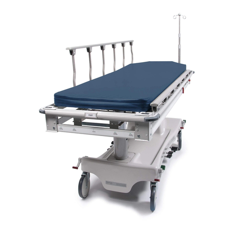
Hausted HORIZON Series User manual

462-IN-INS-LAB-REVA16
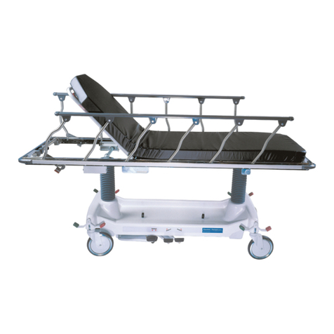
HAUSTED®HORIZON™SERIES STRETCHERS
With AirGlide™Rails:
Models 462APAST,
462CPAST,
462DPAST
With Retracto™Rails:
Models 462EMCST,
462FMCST,
462GMCST,
462HMCST
With 3-Position
Vertical Side Rails:
Model 462EMPST
(Youth)
OPERATING MANUAL
READ THIS MANUAL BEFORE OPERATING YOUR STRETCHER.
SAVE THIS MANUAL FOR FUTURE USE.
THE MOST CURRENT VERSION OF THIS MANUAL CAN BE
FOUND ONLINE AT WWW.HAUSTED.COM.

462-IN-INS-LAB-RevA16 2
CONTENTS
INTRODUCTION — A WORD FROM GF HEALTH PRODUCTS, INC. ......................................................................... 4
INDICATIONS FOR USE ................................................................................................................................... 4
SERVICE INFORMATION.................................................................................................................................. 4
ADVISORY......................................................................................................................................................... 4
1 LIST OF WARNINGS AND CAUTIONS................................................................................................................... 5
SIGNIFICANCE OF SAFETY STATEMENTS .......................................................................................................... 5
WARNING / CAUTION / NOTICE SUMMARY................................................................................................... 5
WARNING: TO REDUCE THE RISK OF PERSONAL INJURY ........................................................... 5
WARNING — CAUTIONS AND PROPER OPERATION ......................................................................................... 5
2 UNCRATING INSTRUCTIONS................................................................................................................................. 7
IMPORTANT — REPORT ANY SHIPPING DAMAGE IMMEDIATELY:................................................................... 7
NOTICE — POSSIBLE EQUIPMENT DAMAGE: .................................................................................................... 7
WARNING — PERSONAL INJURY HAZARD:........................................................................................................ 7
UNPACKING INSTRUCTIONS................................................................................................................................. 7
3 OPERATING INSTRUCTIONS................................................................................................................................. 8
3.1 BRAKING AND STEERING OPERATION......................................................................................................... 8
3.1.1 APPLYING THE BRAKES .................................................................................................................... 8
3.1.2 RELEASING THE BRAKES ................................................................................................................. 8
3.1.3 APPLYING THE STEERING LOCK / FIFTH WHEEL........................................................................... 9
3.1.4 RELEASING THE STEERING LOCK / FIFTH WHEEL........................................................................ 9
3.2 LITTER TOP HEIGHT ADJUSTMENT............................................................................................................. 10
3.2.1 HEIGHT ADJUSTMENT...................................................................................................................... 10
3.2.2 LOWERING LITTER TOP................................................................................................................... 10
3.2.3 TRENDELENBURG ADJUSTMENT................................................................................................... 10
3.2.4 REVERSE TRENDELENBURG ADJUSTMENT ................................................................................ 10
3.3 FOWLER BACKREST OPERATION................................................................................................................11
3.3.1 RAISING THE BACKREST .................................................................................................................11
3.3.2 LOWERING THE BACKREST.............................................................................................................11
3.4 BACKREST / KNEE FLEX OPERATION ........................................................................................................ 12
3.4.1 RAISING THE BACKREST / KNEE FLEX ......................................................................................... 12
3.4.2 LOWERING THE BACKREST / KNEE FLEX .................................................................................... 12
3.5 AIRGLIDE RAIL OPERATION ......................................................................................................................... 13
3.5.1 RAISING THE AIRGLIDE RAIL .......................................................................................................... 13
3.5.2 LOWERING THE AIRGLIDE RAIL ..................................................................................................... 13
3.5.3 INSTALLING THE ARMBOARD ADAPTER AND SURGICAL BAR ................................................. 14
3.6 RETRACTO RAIL OPERATION ...................................................................................................................... 15
3.6.1 RAISING THE RETRACTO RAIL ....................................................................................................... 15
3.6.2 HALF HEIGHT RETRACTO RAIL ...................................................................................................... 15
3.6.3 LOWERING THE RETRACTO RAIL .................................................................................................. 15
3.7 3-POSITION VERTICAL SIDE RAIL OPERATION (YOUTH STRETCHER) .................................................. 16
3.7.1 RAISING THE 3-POSITION VERTICAL SIDE RAIL TO FULL HEIGHT............................................ 16
3.7.2 RAISING THE 3-POSITION VERTICAL SIDE RAIL TO HALF HEIGHT ........................................... 16
3.7.3 LOWERING THE 3-POSITION VERTICAL SIDE RAIL...................................................................... 16
4 SPECIFICATIONS .................................................................................................................................................. 17
ENVIRONMENTAL CONDITIONS (ALL MODELS) .............................................................................................. 17
OPERATING CONDITIONS............................................................................................................................. 17
STORAGE AND TRANSPORT CONDITIONS ................................................................................................ 17
MAXIMUM WEIGHT CAPACITY............................................................................................................................ 17

462-IN-INS-LAB-RevA16 3
SPECIFICATIONS: HORIZON SERIES STRETCHERS WITH AIRGLIDE RAILS
MODELS 462APAST, 462CPAST, 462DPAST ................................................................................................ 17
SPECIFICATIONS: HORIZON SERIES STRETCHERS WITH RETRACTO RAILS
MODELS 462EMCST, 462FMCST, 462GMCST, 462HMCST.......................................................................... 18
SPECIFICATIONS: HORIZON SERIES STRETCHER WITH 3-POSITION VERTICAL SIDE RAILS MODEL
462EMPST ....................................................................................................................................................... 18
5 PREVENTIVE MAINTENANCE FOR THE USER.................................................................................................. 19
6 OPTIONAL ACCESSORIES .................................................................................................................................. 20
HORIZON SERIES STRETCHERS, AS LISTED............................................................................................ 20
7 GF HEALTH PRODUCTS, INC. LIMITED WARRANTY FOR HAUSTED BRAND PRODUCT LINE
OUTSIDE THE U.S................................................................................................................................................. 21
8 DISPOSAL AND KEY TO SYMBOLS.................................................................................................................... 22
DISPOSAL.............................................................................................................................................................. 22
KEY TO SYMBOLS ................................................................................................................................................ 22
9 INDEX ..................................................................................................................................................................... 23
COPYING PROHIBITED
This manual is protected by Federal Copyright Law, which provides for damages of up to USD
$20,000, as well as criminal nes and imprisonment, for unauthorized copying.
© 2016 GF Health Products, Inc. All Rights Reserved Printed in U.S.A.

462-IN-INS-LAB-RevA16 4
INTRODUCTION — A WORD FROM GF HEALTH PRODUCTS, INC.
This manual contains important information on proper use and maintenance of the Hausted
Horizon Stretcher. All personnel involved in the use and maintenance of this equipment
must carefully review and comply with the warnings, cautions and instructions contained in
this manual. These instructions are important to protect the health and safety of personnel
operating model 462 and should be retained in a conveniently accessible area for quick
reference.
Complete instructions for uncrating and putting your new equipment in service, as well as
equipment drawings, have been furnished. If missing, contact GF Health Products, Inc. for
replacement copies, giving the serial number and model number of the unit.
GF Health Products, Inc. carries a complete line of accessories for use with these stretchers;
your representative will gladly review these with you.
Indications for Use
The Hausted Horizon Series Multi-Purpose Stretchers and Youth Care Stretchers are intended
for patient transport, treatment and recovery.
Service Information
A thorough preventive maintenance program is essential to safe and proper unit operation.
This manual contains maintenance schedules and procedures which should be followed for
satisfactory equipment performance.
We encourage you to contact GF Health Products, Inc. with maintenance concerns.
Advisory
A listing of the safety precautions to be observed when operating and servicing this equipment
can be found in Section 1 of this manual. Do not operate or service the equipment until you
have become familiar with this information. Any alteration of this equipment not authorized or
performed by GF Health Products, Inc., could affect its operation, will void the warranty, could
violate national, state, and local regulations, and could jeopardize your insurance coverage.
EC REP
EC Authorized
Representative:
CEpartner4U BV
ESDOORNLAAN 13
3951DB MAARN
The Netherlands
+31(0)6 516 536 26
Manufactured by:
GF Health Products, Inc.
336 Trowbridge Drive
Fond du Lac, WI 54937
770-368-4700 Main
770-368-2386 Fax
www.grahameld.com
www.Hausted.com
Info: The base language of this document is ENGLISH. Any translations must be made from
the base language document.
Class 1 Equipment
Type B Equipment
Equipment not suitable
for use in the presence
of ammable anesthetic
mixture with air or oxygen
or nitrous oxide.
IPX6
Not suitable for
continuous operation
(Duty Cycle:
10% 2 Min in 18 Min)

462-IN-INS-LAB-RevA16 5
1 LIST OF WARNINGS AND CAUTIONS
IMPORTANT: Before using the Hausted Horizon Stretcher, please read and adhere to
the following safety precautions and warnings. Failure to do so could result in serious
personal injury or damage to the Stretcher.
Always consult your healthcare professional to determine safe methods most suitable for
your individual abilities. Protect yourself, your attendant, and the Hausted Horizon Stretcher
by having it serviced regularly. If you experience any malfunction, contact your Graham-Field
authorized distributor immediately, as a hazardous condition could result, causing personal
injury or damage to the Stretcher.
Periodic inspection, adjustment and replacement of worn parts are necessary to provide years
of excellent service. Maintenance MUST be performed by qualied personnel ONLY.
SAVE THESE INSTRUCTIONS.
SIGNIFICANCE OF SAFETY STATEMENTS
Please note the following special statements, used throughout this manual, and their
signicance:
WARNING: Indicates a potential hazard situation or unsafe practice that, if not avoided,
could result in death or serious personal injury.
CAUTION: Indicates a potential hazard situation or unsafe practice that, if not avoided,
could result in minor or moderate personal injury.
sNOTICE: Indicates a potential hazard situation or unsafe practice that, if not avoided,
could result in product or property damage.
Info: Provides application recommendations or other useful information to ensure that you
get the most from your product.
WARNING / CAUTION / NOTICE Summary
The following is a listing of the safety precautions which must be observed when operating
and servicing this equipment. These precautions are repeated (in whole or in part), where
applicable, throughout the manual.
WARNING: To Reduce the Risk of Personal Injury
WARNING: LACERATION HAZARD — When cutting bands always us a tool specically
designed for that purpose. This will help to avoid personal injuries frequently incurred
when bands are cut and tension released.
WARNING — CAUTIONS AND PROPER OPERATION
WARNING: Horizon series Stretcher models 462APAST, 462CPAST, 462EMCST,
462GMCST, and 462EMPST have a maximum weight capacity of 500 lb (227 kg).
Horizon series Stretcher models 462DPAST, 462FMCST, and 462HMCST have a
maximum weight capacity of 800 lb (363 kg).
WARNING:
Patient entry, egress and transfer should always be done with the brakes
locked.
WARNING: The caster braking system should always be locked when patient is not in
transport.

462-IN-INS-LAB-RevA16 6
WARNING: The caster braking system should always be locked and patient side rails in
upright locked position when patient is left unattended.
WARNING: Always ensure side rails are in upright locked position before leaving patient
unattended.
WARNING: Do not sit on head or foot end — tipping may occur.
WARNING: Do not modify the equipment without the authorization of the manufacturer.
WARNING: NOTICE FOR CALIFORNIA CUSTOMERS- California Proposition 65 Warning:
This product contains a chemical known to the State of California to cause cancer and
reproductive or developmental harm.
CAUTION: When lowering the rails, ensure patient and caregiver body and extremities
are clear of pinch points before operating the rail.

462-IN-INS-LAB-RevA16 7
2 UNCRATING INSTRUCTIONS
IMPORTANT — REPORT ANY SHIPPING DAMAGE IMMEDIATELY:
WARNING:Inform shipper of any damage — leave carton intact. Leave equipment in the
receiving area until inspection is complete.
NOTICE — POSSIBLE EQUIPMENT DAMAGE:
sNOTICE: The crate contains fragile, expensive medical equipment. Uncrate and handle
carefully. If after uncrating the equipment you nd any damage (no matter how slight),
report the damage to GF Health Products, Inc.
WARNING — PERSONAL INJURY HAZARD:
WARNING: When cutting bands, always use tool specically designed for that purpose.
This will help avoid personal injuries possibly incurred when bands are cut and tension
is released.
UNPACKING INSTRUCTIONS
IMPORTANT: Follow each step in the order shown in these instructions.
Your Hausted equipment has been carefully packed at our manufacturing plant to ensure safe
shipment to your medical facility. There are several procedures you must follow to put your
new equipment in service. These procedures only take a few minutes to complete and all are
required to ensure proper operation of the equipment.
1. Cut the two bands around the shipping carton.
2. Remove the top half of the carton and cut one side of the bottom half.
3. Remove the equipment from the carton.
4. Check to see if all features of the equipment work properly. If all the features work, advance
to step 5. If any features do not work properly, call GF Health Products, Inc. at 770-368-4700.
5. Clean the equipment using mild detergent to remove any dirt accumulated during shipment,
and place the equipment into service.

462-IN-INS-LAB-RevA16 8
3 OPERATING INSTRUCTIONS
3.1 BRAKING AND STEERING
OPERATION
WARNING—PERSONAL INJURY
HAZARD AND / OR EQUIPMENT
DAMAGE HAZARD:
The caster braking system should
always be locked when patient is not in
transport.
The caster braking system should
always be locked and patient side rails
in upright locked position when patient
is left unattended.
WARNING—PROPER OPERATION
HAZARD:
Floors must be smooth and level to
maintain optimum fth wheel steering.
Fifth wheel steering functions can be
inuenced by oor irregularities (bumps
or dips) greater than 1/2" (13 mm)
across the span of the stretcher.
3.1.1 Applying the Brakes
Activate the four-wheel central braking
system by depressing the red pedal at any of
the unit’s four corners (Figure 3-1). To fully
engage brakes, press pedal to approximately
45°. All four caster wheels will then be
locked from swiveling and rotating.
3.1.2 Releasing the Brakes
Depress the green pedal at any of the unit’s
four corners until the pedal is in a horizontal
position (Figure 3-2). All four wheels will
then rotate and swivel freely.
WARNING: The caster braking system
should always be locked when patient is
not in transport.
Figure 3-1
Figure 3-2

462-IN-INS-LAB-RevA16 9
WARNING—PROPER OPERATION
HAZARD:
Floors must be smooth and level to
maintain optimum fth wheel steering.
Fifth wheel steering functions can be
inuenced by oor irregularities (bumps
or dips) greater than 1/2" (13 mm)
across the span of the stretcher.
3.1.3 Applying the Steering Lock /
Fifth Wheel
Depress the green pedal at any of the unit’s
four corners downward into locked position.
(Figure 3-3). Steering lock – one caster at foot
end locks into non-swivel mode, allowing
straight steering by the attendant. Fifth
wheel – a center-steer caster lowers and
applies pressure to oor, allowing straight
steering by the attendant.
3.1.4 Releasing the Steering Lock /
Fifth Wheel
Depress the red pedal at any of the unit’s
four corners until the pedal is in a horizontal
position (Figure 3-2). All four wheels will then
rotate and swivel freely, and / or optional
fth wheel lifts off oor.
Figure 3-3

462-IN-INS-LAB-RevA16 10
3.2 LITTER TOP HEIGHT
ADJUSTMENT
3.2.1 Height Adjustment
Press pump pedal to oor (Figure 3-4), then
release. Repeat this process until desired
height is obtained. Use smooth strokes on
pump pedal to ensure patient comfort.
3.2.2 Lowering Litter Top
Press down on two release pedals at the
same time (Figure 3-5) until desired height is
obtained.
sNOTICE: Do not stand on release
pedals.
3.2.3 Trendelenburg Adjustment
Place unit at maximum height: see “Height
Adjustment” above. Press down on the
release pedal nearest the head end (Figure
3-6) until desired position is obtained, then
remove pressure.
3.2.4 Reverse Trendelenburg
Adjustment
Place the unit at maximum height: see
“Height Adjustment” above. Press down
on release pedal nearest foot end (Figure
3-7) until desired position is obtained, then
remove pressure.
Figure 3-4
Figure 3-5
Figure 3-6
Figure 3-7

462-IN-INS-LAB-RevA16 11
3.3 FOWLER BACKREST
OPERATION
3.3.1 Raising the Backrest
Grasp fowler backrest frame tube and gas
spring activating handle from either side of
stretcher. Squeeze handle and tube together
and lift. Once desired incline is achieved,
release handle.
Info: the amount of manual lifting required
will vary depending on patient size; the gas
spring is intended only to assist in lifting
patient.
3.3.2 Lowering the Backrest
Grasp fowler backrest frame tube and gas
spring activating handle from either side of
the stretcher. See Figure 3-8. Squeeze handle
and tube together while supporting fowler.
Adjust incline either by slowly lowering
patient or by pressing fowler down. Release
handle once desired incline is achieved.
Info: the amount of manual support
required will vary depending on patient
size; the gas spring is intended only to
assist in lowering patient.
Figure 3-8

462-IN-INS-LAB-RevA16 12
3.4 BACKREST / KNEE FLEX
OPERATION
3.4.1 Raising the Backrest / Knee
Flex
To elevate backrest or knee ex, ip crank
handle upwards, and rotate crank handle
clockwise. See Figure 3-9. When reaching
desired position, stop rotating handle and
return crank handle to its original position.
See Figure 3-10.
3.4.2 Lowering the Backrest / Knee
Flex
To lower backrest or knee ex, ip crank
handle upwards, and rotate crank handle
counterclockwise, See Figure 3-9. When
reaching desired position, stop rotating
handle and return crank handle to its original
position. See Figure 3-10.
Figure 3-9
Figure 3-10

462-IN-INS-LAB-RevA16 13
3.5 AIRGLIDE RAIL OPERATION
(Models 462APAST, 462CPAST, 462DPAST)
3.5.1 Raising the AirGlide Rail
Refer to Figures 3-11A & 3-11B. Grasp rail top
tube from under litter top rmly, then pull up
until rail locks into full up position.
WARNING: Verify latching of rail before
leaving patient unattended.
3.5.2 Lowering the AirGlide Rail
Firmly grasp top of rail, pull out on red tab
located under litter top at foot or head end
(Figure 3-12). Lower side rail completely
under litter top.
WARNING: Always ensure side rails are
in upright locked position before leaving
patient unattended.
Figure 3-11A
Figure 3-11B
Figure 3-12

462-IN-INS-LAB-RevA16 14
3.5.3 Installing the Armboard Adapter
and Surgical Bar
1. Refer to Figure 3-13. Install surgical bar
adapter by positioning adapter over
bumper channel and pad, then slide
adapter downward until it rests on
channel.
2. Refer to Figure 3-14. Secure adapter
by inserting tethered pin into hole in
adapter. Insert fully until pin is locked
through both sides of the adapter.
3. Refer to Figures 3-15A and 3-15B. Mount
armboard to adapter by tilting armboard
upwards slightly, engaging upper portion
of clamp over surgical bar on adapter.
a. Once armboard is engaged with
surgical bar, lower to horizontal
position to lock.
b. To remove armboard, depress gravity
latch and lift armboard from surgical
bar.
Figure 3-13
Figure 3-14
Figure 3-15A
Figure 3-15B

462-IN-INS-LAB-RevA16 15
3.6 RETRACTO RAIL OPERATION
(Models 462EMCST, 462FMCST, 462GMCST,
462HMCST)
WARNING—–PROPER OPERATION
HAZARD:
Patient entry, egress and transfer
should always be done with caster
braking system locked.
Caster braking system should always be
locked and patient side rails in upright
locked position when patient is left
unattended.
3.6.1 Raising the Retracto Rail
Grasp rail top cap in the middle of the rail
(Figure 3-16), and lift.
3.6.2 Half Height Retracto Rail
Grasp the rail (Figure 3-16) and lift up on
red trigger under the litter top (Figure 3-17)
while lowering rail. When rail starts to move
down, release trigger. Lower rail until it locks
into half height position.
3.6.3 Lowering the Retracto Rail
Grasp the rail (Figure 3-16) and lift up on
red trigger under the litter top (Figure 3-17)
while lowering rail. Hold the trigger up until
the rail is all the way down.
CAUTION: When lowering the rails,
ensure patient and caregiver (or
attendant) body and extremities are
clear of pinch points before operating
the rail.
WARNING: Always ensure side rails are
in upright locked position before leaving
patient unattended.
Figure 3-18
Figure 3-17
Figure 3-16

462-IN-INS-LAB-RevA16 16
3.7 3-POSITION VERTICAL SIDE RAIL
OPERATION (YOUTH STRETCHER)
(Model 462EMPST)
WARNING–PROPER OPERATION HAZARD:
Patient entry, egress and transfer should always
be done with caster braking system locked.
Caster braking system should always be locked
and patient side rails in upright locked position
when patient is left unattended.
3.7.1 Raising the 3-Position Vertical Side Rail
to Full Height
Refer to Figure 3-18A & 3-18B. Grasp the rail top tube
in the center of the rail. With free hand, squeeze the
rail trigger and lift the rail all the way up. Once the rail
is all the way up, release the rail trigger and lower the
rail slowly until the trigger engages. Check rail lock
by trying to squeeze the rail trigger—if you cannot
squeeze the trigger, the rail is locked securely. Release
the rail top tube.
WARNING: Always ensure side rails are in upright
locked position before leaving patient unattended.
3.7.2 Raising the 3-Position Vertical Side Rail
to Half Height
Refer to Figure 3-18B. Grasp rail top tube in center of
rail and raise rail until it engages. Check rail lock by
trying to squeeze rail trigger. If trigger will not squeeze,
the rail is locked securely. Release rail top tube.
WARNING: Always ensure side rails are in upright
locked position before leaving patient unattended.
3.7.3 Lowering the 3-Position Vertical Side
Rail
Refer to Figure 3-18C. Grasp top tube in center of rail
and squeeze rail trigger with free hand while lifting
slightly on rail. This should allow rail trigger to release
trigger lock. Lower rail slowly. If ‘half height’ is desired,
release rail trigger as soon as the rail starts lowering.
If ‘full down’ is desired, continue to squeeze the trigger
until rail is completely lowered.
WARNING: Always ensure side rails are in upright
locked position before leaving patient unattended.
Figure 3-18A
Figure 3-18B
Figure 3-18C

462-IN-INS-LAB-RevA16 17
4 SPECIFICATIONS
ENVIRONMENTAL CONDITIONS (ALL MODELS)
Operating Conditions
Temperature 10°C to 40°C
Relative Humidity 20% to 90% @ 30°C
Atmospheric Pressure 700 hPa to 1060
hPa
Storage and Transport Conditions
Temperature -10°C to 50°C
Relative Humidity 20% to 90% @ 30°C
Atmospheric Pressure 700 hPa to 1060
hPa
MAXIMUM WEIGHT CAPACITY
WARNING: Horizon series Stretcher models 462APAST, 462CPAST, 462EMCST,
462GMCST, and 462EMPST have a maximum weight capacity of 500 lb (227 kg).
Horizon series Stretcher models 462DPAST, 462FMCST, and 462HMCST have a maximum
weight capacity of 800 lb (363 kg).
All Horizon stretchers have a warning label at head or foot end of stretcher top frame that
states maximum weight capacity. Those models whose weight capacity has been increased
(462EMPST, 462DPAST, 462FMCST, and 462HMCST) can be identied by this weight capacity
label at head or foot of stretcher top frame, as well as the navy bumper channel and rail cap;
earlier models with lower weight capacity, and those with unchanged weight capacity, have a
gray bumper channel and rail cap.
SPECIFICATIONS: HORIZON SERIES STRETCHERS WITH AIRGLIDE RAILS
MODELS 462APAST, 462CPAST, 462DPAST
Specication
Model Standard Width
462APAST, 462CPAST
Wide Width
462DPAST
Maximum Height 34.75 in (88 cm) 34.75 in (88 cm)
Minimum Height 22 in (56 cm) 22 in (56 cm)
Overall Width 31.25 in (79.4 cm) 35 in (89 cm)
Overall Length 83 in (210 cm) 83 in (210 cm)
Patient Surface Width 28 in (71 cm) 32 in (81 cm)
Patient Surface Length 76 in (193 cm) 77 in (196 cm)
Backrest Degree of Movement 0° - 90° 0° - 90°
Knee Flex Degree of Movement 0° - 70° (CPA) 0° - 70°
Trendelenburg / Reverse Trendelenburg 16° 16°
AirGlide Rail Height 15 in (38 cm) 15 in (38 cm)
AirGlide Rail Length 75 in (190 cm) 75 in (190 cm)
Casters 8 in Tente®(20 cm) 8 in Tente®(20 cm)
Maximum Weight Capacity (Evenly Distributed) 500 lb (227 kg) 800 lb (363 kg)
Pad 4 in (10 cm) 4 in (10 cm)

462-IN-INS-LAB-RevA16 18
SPECIFICATIONS: HORIZON SERIES STRETCHERS WITH RETRACTO
RAILS MODELS 462EMCST, 462FMCST, 462GMCST, 462HMCST
Specication
Model Standard Width
462EMCST, 462GMCST
Wide Width
462FMCST, 462HMCST
Maximum Height 34.75 in (88 cm) 34.75 in (88 cm)
Minimum Height 22.25 in (56.5 cm) 22.25 in (56.5 cm)
Overall Width 30 in (76 cm) 34.5 in (87.6 cm)
Overall Length 83 in (210 cm) 83 in (210 cm)
Patient Surface Width 25 in (63.5 cm) 30 in (76 cm)
Patient Surface Length 76 in (193 cm) 77 in (196 cm)
Backrest Degree of Movement 0° - 90° 0° - 90°
Knee Flex Degree of Movement 0° - 70° (GMC) 0° - 70° (HMC)
Trendelenburg / Reverse Trendelenburg 16° 16°
Retracto Rail Height 15 in (38 cm) 15 in (38 cm)
Retracto Rail Length 60 in (152 cm) 60 in (152 cm)
Casters 8 in Tente®(20 cm) 8 in Tente®(20 cm)
Maximum Weight Capacity (Evenly Distributed) 500 lb (227 kg) 800 lb (363 kg)
Pad 4 in (10 cm) 4 in (10 cm)
SPECIFICATIONS: HORIZON SERIES STRETCHER WITH 3-POSITION
VERTICAL SIDE RAILS MODEL 462EMPST
Specication
Model 462EMPST
Maximum Height 37 in (94 cm)
Minimum Height 28.5 in (92.4 cm)
Overall Width 30 in (76 cm)
Overall Length 83 in (210 cm)
Patient Surface Width 25 in (63.5 cm)
Patient Surface Length 76 in (193 cm)
Backrest Degree of Movement 0° - 90°
Knee Flex Degree of Movement -
Trendelenburg / Reverse Trendelenburg 12°
Vertical Rail Height 16 in (41 cm)
Vertical Rail Length 73 in (185 cm)
End Rail Height 16 in (41 cm)
End Rail Length 23 in (58 cm)
Spindle Gap Maximum 2.5 in (6 cm)
Spindle Gap Minimum 4 in (10 cm)
Casters 8 in Tente® (20 cm)
Maximum Weight Capacity (Evenly Distributed) 500 lb (227 kg)
Pad 3 in (8 cm)

462-IN-INS-LAB-RevA16 19
5 PREVENTIVE MAINTENANCE FOR THE USER
Component Cleaning Procedure Schedule Cleaning Agent * Special Notes
Pads /
Mattresses
Wipe with damp cloth to
remove any foreign material
After each
use
Routine hospital
grade disinfectants,
soap and water
Use only medium
strength cleaners
Do not steam clean or
pressure wash
Stretcher Wipe with damp cloth to
remove any foreign material
After each
use
Routine hospital
grade disinfectants,
soap and water
Lubricate pivot points
after cleaning
Electrical
components
Wipe external surfaces ONLY
with damp cloth to remove
any foreign material
After each
use
Routine hospital
grade disinfectants,
soap and water
Use only medium
strength cleaners
Mechanical
stretcher
components
Wipe with damp cloth to
remove any foreign material
After each
use
Routine hospital
grade disinfectants,
soap and water
Lubricate pivot points
after cleaning
Mechanical
accessories
Wipe with damp cloth to
remove any foreign material
After each
use
Routine hospital
grade disinfectants,
soap and water
Lubricate pivot points
after cleaning
Procedure Schedule Material
Lubricate all moving and sliding parts and
hinge points
Every 3
months
Lubricating oil, light-duty grease, wax stick
lubricant or Never-Seez lubricant
NEVER LUBRICATE GAS SPRING, MOTOR OR MECH-LOCK SHAFTS
Inspect all fasteners to ensure proper t,
position and tightness (including nuts, bolts,
etc.)
Every 3
months
Proper size wrench and screwdriver
Inspect all surfaces and remove any sharp
or burred areas; apply touch-up paint where
required
Every 3
months
Metal le, proper color paint (specify color
when ordering)
*Disinfectants, vinyl products: Phenolic disinfectants are the best choice for vinyl products; properly diluted
quaternaries are also acceptable. Quaternary / Isopropyl disinfectants are not recommended for vinyl.
Disinfectants, urethane products: Quaternary disinfectants are recommended for urethane products.
Quaternary / Isopropyl disinfectants are recommended for urethane. Phenolics should be avoided on
urethane.
Disinfectants, all products: All fabrics may be cleaned with a 1:10 dilution of household bleaches containing
5.25% sodium hypochlorite as recommended by the Centers for Disease Control in Atlanta, Georgia. There is
no harmful effect on the fabric. Disinfectants applied at full concentration or in highly concentrated solutions
will decrease the useful life of fabric. Iodophor type disinfectants used on fabrics may result in staining.
Soils or Stains: Use neutral soapsuds and lukewarm water. Do not use harsh cleansers, solvents or detergents.
Hard-To -Clean Spots: Use standard household / vinyl cleansers and a soft bristle brush on troublesome spots
or stains. Presoak heavy, dried-on soil.
Laundering Vinyl-laminated or Rubber-coated fabric is not recommended. Laundering may substantially
decrease the useful life of the fabric.
Laundering Polyurethane-coated fabric: Machine wash with detergent up to 120°F. Some surface wrinkling
may occur; this wrinkling has no adverse effect on the fabric properties. Hang or tumble dry thoroughly at
140°F before storage.
sNOTICE — POSSIBLE EQUIPMENT DAMAGE HAZARD: Steam cleaning and pressure
washing of stretcher is not recommended and can void warranty.
Info: For more detailed information, please contact GF Health Products, Inc. at 770-368-4700.
Info: In addition to the User Preventive Maintenance, a more detailed Preventive
Maintenance Program is also required to keep the equipment in good working order. This
Preventive Maintenance Program is found on our website, at www.Hausted.com.

462-IN-INS-LAB-RevA16 20
6 OPTIONAL ACCESSORIES
Horizon Series Stretchers, as Listed
Model
Item No. Description
H07633400 Armboard and Surgical Bar Adapter XXXXX
H06518000 Armboard w/1 in (2.5 cm) Pad and Adapter XXX
H00005400 Lateral X-Ray Cassette Holder XXXXX
H131490 Articulating Headrest 22 1/4 in (56.5 cm) X X X
H131495 Articulating Headrest 27 in (69 cm) X X
HSA094100 Standard Articulating Headrest 18 in (46 cm) X X
HSA0942 Extra-Wide Articulating Headrest 21 in (53 cm) X
H06883600 Footboard w/ Monitor Shelf and Chartholder X X X
H06884600 Footboard w/ Monitor Shelf and Chartholder X X
H06929900 Footboard w/ Monitor Shelf and Chartholder X
H06883500 Footboard w/ Monitor Shelf and Chartholder X X
H00006B00 Stationary Head/Footboard X X X
H000W6B00 Head/Footboard (Extra-Wide) X X
H00CR6B00 Footboard w/ Chart Holder X X X
H0CRW6B00 Footboard w/ Chart Holder (Extra-Wide) X X
H06722500 Head/Footboard w/ Chart Holder (Extra Wide) X X
H06938100 Head/Footboard w/ Chart Holder (Stationary) X
H00N16A00 Heel Stirrups w/ Mounting Adapter XXXXX
H00C16H00 Heel Stirrups (Pair) XXX
H00L16M00 Mounting Adapter Clamps For Stirrups XXX
H000E1700 Fixed Height IV Pole, 42 in (107 cm) XXXXXXXX
H000018 Telescoping IV Pole 27 in - 54 in (68 cm - 137 cm) XXXXXXXX
H06589700 Mobile IV Stand Attachment XXXXX
HIVSTOW00 Mobile IV Stand Attachment XXX
H06925700 Paper Roll Holder XXXXXXXX
H06536600 Universal Patient Tray XXXXXXXX
H13317000 Under-Fowler Utility Tray X X X
H13317100 Under-Fowler Utility Tray (Extra Wide) X X
H07565600 Push Handle Assembly - Bumpered XXXXX
H07566400 Push Handle Assembly - Tube Top X X
H07566500 Push Handle Assembly - Tube Top X
H12845000 Vertical Oxygen Tank Holder Assembly XXXXXXXX
H076336 Surgical Accessory Rail (Retracto) XXXXX
H076540 Surgical Accessory Rail (AirGlide) XXX
H07562600 Rail Pad Cover (6 Leg Retracto Rail) XXXX
H06774100 Side Rail Pads X X X X
H00P11R00 Side and End Rail Pads X
WARNING: It is recommended that only accessories approved by GF Health Products,
Inc. be used with this device.
Info: To order accessories, or for more detailed information on accessories, please contact
GF Health Products, Inc. at 770-368-4700.
462APAST
462CPAST
462DPAST
462EMCST
462FMCST
462GMCST
462HMCST
462EMPST
Other manuals for HORIZON Series
3
This manual suits for next models
8
Table of contents
Other Hausted Medical Equipment manuals

Hausted
Hausted APC Series User manual

Hausted
Hausted ESC2 User manual

Hausted
Hausted Horizon 462 - A User manual

Hausted
Hausted APC Series User manual

Hausted
Hausted ESC2EYEST User manual

Hausted
Hausted MBC User manual

Hausted
Hausted HORIZON Series User manual

Hausted
Hausted HORIZON Series User manual

Hausted
Hausted UNICARE Series Service manual

Hausted
Hausted EPC500ST User manual