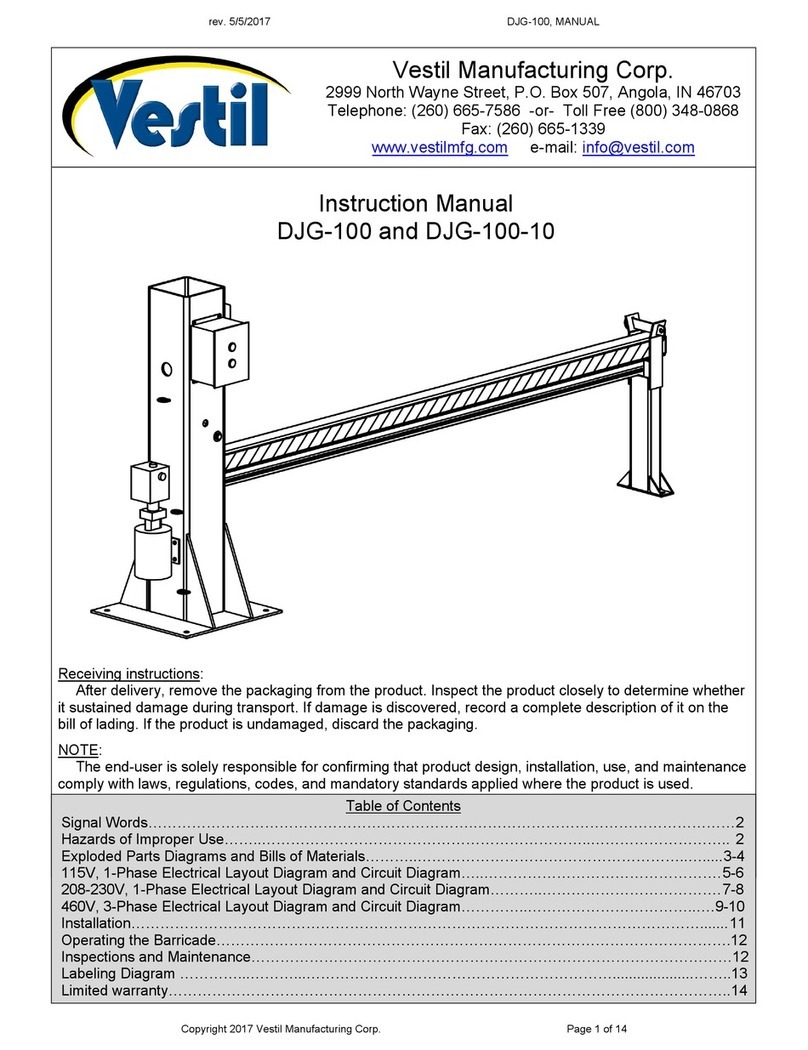
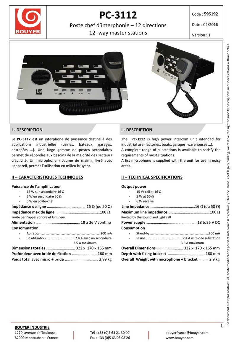
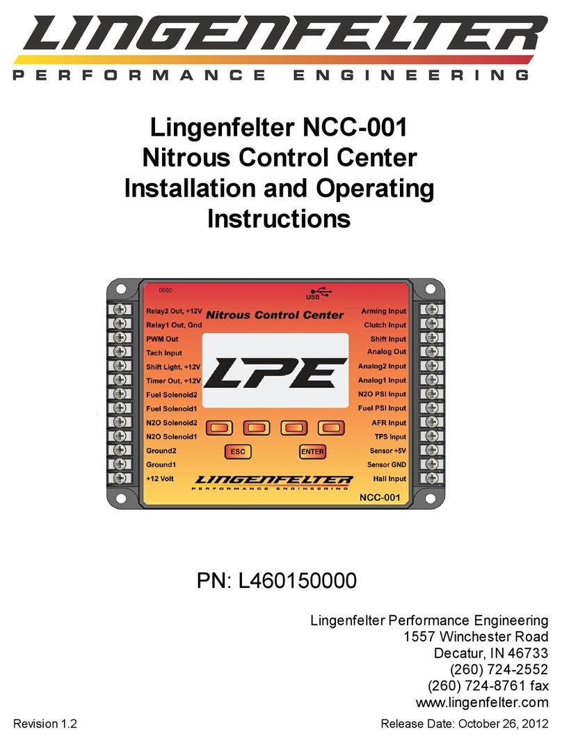
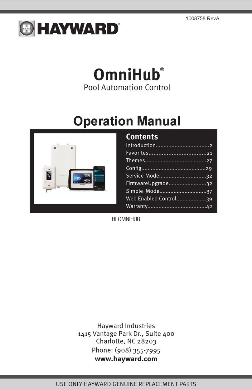
HAUTAU WLAN-Box User manual

© HAUTAU GmbH
Reprint, even in excerpts, not without the publisher’s approval.
In consideration of progress, we reserve the right to apply construction modifications and to consequently change any figures, dimensions, wire specifications etc.
The figures do not show items in their actual size and are also not of the same proportion.
03/2021 500384F
© HAUTAU GmbH
Nachdruck, auch auszugsweise, nur mit schriftlicher Genehmigung des Herausgebers.
Im Sinne des Fortschritts behalten wir uns Konstruktionsänderungen und dadurch bedingte Abweichungen von Abbildungen, Abmessungen, Leitungsangaben
usw. vor. Die Abbildungen zeigen die Artikel nicht in natürlicher Größe und stehen auch nicht im gleichen Verhältnis zueinander.
t
D
Produktbeschreibung
Die WLAN-Box dient zur drahtlosen Steuerung von Produkten
mit einer HAUTAU-Busschnittstelle per WLAN-Funk signal.
Die Steuerung erfolgt durch mobile Endgeräte über eine
Direkt verbindung zur WLAN-Box oder über bauseitige WLAN-
Router. Zur Steuerung und Konfiguration der Produkte wird
das optional erhältliche HAUTAU ConfigTool benötigt.
Product description
The WLAN-Box is to be used for wireless control of products with
a HAUTAU bus interface via WLAN radio signal.
The control will be effected by means of mobile terminals via a
direct connection to the WLAN-Box or via on-site WLAN routers.
For control and configuration of the products, the optional available
HAUTAU ConfigTool is required.
Inhaltsverzeichnis
Seite
Wichtige Sicherheitsanweisungen ........................................... 2
Installationshinweise, Merkmale .............................................. 3
Anwendungsbeispiele und Leitungsverlegeplan ...................... 4
Geräteübersicht ...................................................................... 5
Leitungslängen und Querschnitte ............................................ 6
Montage der WLAN-Box ........................................................ 6
Anschlussplan ........................................................................ 7
Optische Signale und Tastenbelegung .................................... 10
WLAN-Anmeldung ................................................................ 11
Funktionsbeschreibung ......................................................... 11
Technische Daten ................................................................. 12
Table of content
page
Important safety instructions ..................................................... 2
Installation information, Features ............................................... 3
Application examples and wiring diagram ................................. 4
Equipment overview ................................................................. 5
Wire lengths and cross-sections .................................................. 6
Installation of the WLAN-Box ..................................................... 6
Terminal connection diagram .................................................... 7
Optical signals and assignment of keys ....................................... 10
WLAN log-in ........................................................................... 11
Functional description ............................................................. 11
Technical data ........................................................................ 12
WLAN-Box
Montage- und Betriebsanleitung | Installation and operating instructions
zur drahtlosen Steuerung von Produkten mit HAUTAU-Busschnittstelle
for wireless control of products with HAUTAU bus interface

2
ACHTUNG
Für die Sicherheit von Personen ist es
wichtig, die folgenden Anweisungen
zu befolgen. Falsche Montage kann zu
schweren Verletzungen oder zum Tod
führen!
Die WLAN-Box entspricht dem
aktuellen Stand der Technik. Dies
betrifft Leistungsfähigkeit, Material,
Funktions weise und den sicheren
Betrieb.
Lebensgefahr durch Stromschlag!
Die WLAN-Box ist geeignet zur
Ansteuerung von 230 V-Produkten
mit einer HAUTAU-Busschnittstelle.
Es besteht Lebensgefahr durch das
Berühren stromführender Teile.
Bei Wartungsarbeiten an Systemen
mit 230 V trennen Sie diese mittels
Trennvorrichtung allpolig vom Netz
und sichern Sie diese vor unbe-
absichtigtem Wiedereinschalten.
Die Trennvorrichtung muss deutlich
gekennzeichnet sein.
Quetsch- und Klemmgefahr!
Sichern Sie Quetsch- und Scherstellen
zwischen Fensterflügeln und Rahmen,
Lichtkuppeln und Aufsatzkranz bis
zu einer Höhe von 2,5 m durch Ein-
richtungen, die bei Berührung und
Unter brechung durch eine Person die
Bewegung zum Stillstand bringen.
WARNING:
Important safety instructions!
WARNUNG:
Wichtige Sicherheitsanweisungen!
ATTENTION
The safety of personnel requires that
the following instructions be observed.
Incorrect installation can lead to severe
injury or to death!
The WLAN-Box corresponds with the
actual standard of technology.
This affects performance, material,
functioning and the safe operation.
Mortal danger due to electricity!
The WLAN-Box is suitable for control
of 230 V products with a HAUTAU bus
interface. Mortal danger by touching
cables that are live.
During service/maintenance at the
unit, the supply voltage has to be dis-
connected via isolating link at all poles.
Protect the system against unintentional
re-starting. The isolating link has to be
labeled clearly.
Danger!
Crushing and cutting points!
Potential crushing and cutting points
between the casement and the
window frame, dome lights and
support frame must be secured up
to a height of 2,5 m by safety equip-
ment, which if touched or interrupted
by a person will immediately stop the
move ment.
Die Montage ist von sach kundigem und
sicher heits bewusstem Elektro- Fach personal
ent sprechend dieser Montage- und Betriebs-
anleitung durchzuführen. Hierzu zählen Elektro-
installateure oder Fach einrichter mit einer
Schulung auf dem Gebiet der Elektro installation.
Alle Arbeiten an netzspannungsführenden
Bauteilen dürfen nur durch eine Fachkraft
mit abgeschlossener Ausbildung im Bereich
Elektro installation durch geführt werden.
The mounting has to be performed by trained,
qualified and safety-conscious electrical staff
acc. to this mounting and operating instruction.
These include electrical fitters or skilled fitters
with training in the field of electrical equipment
installation.
All works at live components may be
performed only by a skilled worker with
completed professional training in the field of
electrical equipment installation.

3
Installation information
Connect all components only in accordance with the terminal
connection diagrams included with the products.
You absolutely have to observe the building regulations of the
respective country.
All wires except the feeder wire conduct 24 V DC and
must not be laid to gether with electric power lines (observe
VDE regulations or equivalent). When installing the drives, please
pay attention to the occurring forces.
Finish by checking all functions as well as function and operation
displays and the pivoting range of the drives. Complete the
assembler’s certificate included in the control book and forward
the request form and the corresponding envelope to the
operator.
All drawings, installation and operating instructions must
be kept for future reference.
Installationshinweise
Anschluss aller Bauteile nur nach Anschlussplänen, welche
den Produkten beigefügt sind.
Beachten Sie zwingend die DIN, VDE sowie Vorschriften der
Berufsgenossenschaften und die Landesbauordnung (Auswahl
VDE 0100, VDE 0833, VDE 0800, BGV).
Alle Leitungen, außer der Netzzuleitung, führen 24 V DC.
Verlegen Sie diese nicht zusammen mit Starkstromleitungen
(VDE-Vorschriften beachten). Bei der Montage der Antriebe
beachten Sie bitte die auftretenden Kräfte.
Überprüfen Sie zum Abschluss alle Funktionen, Funktions- und
Betriebsanzeigen sowie den Schwenkbereich der Antriebe.
Füllen Sie die Errichter bescheinigung im Kontrollbuch aus und
leiten Sie das Anforderungsformular sowie den dazugehörigen
Brief umschlag an den Betreiber weiter.
Zeichnungen, Montage- und Betriebsanleitung sind für
einen späteren Gebrauch aufzubewahren.
Merkmale
- zum Einbau in eine Unter-Putz-Dose (UP)
- zur Steuerung von max. 31 Teilnehmern mit HAUTAU-Bus-
Schnittstelle
- Steuerung und Konfiguration per WLAN
(Wireless Local Area Network)
- sicherer Datenaustausch per WPA Verschlüsselung
(Wi-Fi Protected Access)
- Anmeldung an bauseitige Router per WPS
(Wi-Fi Protected Setup)
- optisches Signal für Rückmeldungen für Betrieb und
Konfiguration
- Anschlussmöglichkeit für einen kabelgebundenen
Lüftungstaster
- Übergeordneter Eingang zur Verriegelung
Features
- for installation in a flush housing
- for control of max. 31 participants with HAUTAU bus interface
- control and configuration by means of WLAN
(Wireless Local Area Network)
- safe data exchange by means of WPA encryption
(Wi-Fi Protected Access)
- Logon at on-site routers by means of WPS
(Wi-Fi Protected Setup)
- optical signal for feedback for operation and configuration
- connection possibility for a wired ventilation pushbutton
- superordinated input for locking

4
Application examples and wiring diagramAnwendungsbeispiele und Leitungsverlegeplan
1 - Abzweigdose / junction box
2 - WLAN-Box
3 - Smartphone, Tablet
4 - optionaler Lüftungstaster
optional ventilation pushbutton
5 - Netzteil / mains adapter
6 - Router
1 - Abzweigdose / junction box
2 - WLAN-Box
3 - Smartphone, Tablet
4 - optionaler Lüftungstaster
optional ventilation pushbutton
5 - Netzteil / mains adapter
4
5
6
2
11
3
3 x 0,8 mm² 3 x 0,8 mm²
2 x *
3 x *
Betriebsspannung + 24 V DC
Operating voltage + 24 V DC
Antriebs- und Busleitung
Drive line and bus line
*) siehe “Leitungslängen und Querschnitte”
refer to “Wire lengths and cross-sections”
3 x 0,8 mm²
Zuleitung 230 V AC / 50 Hz
Feeder wire 230 V AC / 50 Hz
4
5
11
2
3
Zuleitung 230 V AC
Feeder wire 230 V AC
Betriebsspannung + 24 V DC
Operating voltage + 24 V DC
*) siehe “Leitungslängen und Querschnitte”
refer to “Wire lengths and cross-sections”
Antriebs- und Busleitung
Drive line and bus line
2 x *
3 x 0,8 mm²
3 x 0,8 mm² 3 x 0,8 mm²
3 x *
Anwendungsbeispiel für 24 V DC-Antriebe
(z. B. SKA 20 comfort drive)
Application example for 24 V DC drives
(e. g. SKA 20 comfort drive)
Anwendungsbeispiel für 24 V DC-Antriebe
(z. B. SKA 20 comfort drive) mit Direktverbindung
Application example for 24 V DC drives
(e. g. SKA 20 comfort drive) with direct connection

5
1234567
BUS
GND
24 V
24 V
Application examples and wiring diagram
(cont‘d)
Anwendungsbeispiele und Leitungsverlegeplan
(Forts.)
1 - Abzweigdose / junction box
2 - WLAN-Box
3 - Smartphone, Tablet
4 - optionaler Lüftungstaster
optional ventilation pushbutton
6 - Router
4
6
2
1
11
3
NYM 3 x 1,5 mm²
3 x 0,8 mm²
2 x 0,8 mm²
3 x 0,8 mm²
Zuleitung 230 V AC / 50 Hz
Feeder wire 230 V AC / 50 Hz
Anwendungsbeispiel für 230 V AC-Antriebe (z. B. PRIMAT-E kompakt 195)
mit Anbindung an bauseitigen WLAN-Router
Application example for 230 V AC drives (e. g. PRIMAT-E kompakt 195)
with connection to on-site WLAN router
Geräteübersicht / Equipment overview
Der Anschluss von Schaltern/Tastern ist möglich.
Die Eingänge arbeiten mit Schließerkontakten:
je 1 Eingang für die Befehle AUF und ZU.
Tast-/Schaltbetrieb
Liegt der Befehl < 1,5 s an, erfolgt ein Auf- bzw. Zufahren bis zum
nächsten Befehl.
Ein STOPP erfolgt durch ein gleichzeitiges Schließen beider
Eingänge innerhalb von 0,5 s während der Fahrzeit. Das ermöglicht
den Betrieb sowohl mit zwei Tasten (z. B. Doppel taster) als auch
dem HAUTAU-Lüftungstaster, bei dem die dritte, separate Taste
(STOPP) das gleichzeitige Drücken der beiden anderen Tasten
auslöst.
Totmannbetrieb
Liegt ein Befehl > 1,5 s an, erfolgt ein Auf- bzw. Zufahren, solange
der Kontakt geschlossen ist. Ein STOPP erfolgt durch Öffnen
des Kontaktes ( Loslassen/ Zurückstellen des Bedienelementes/
Schalters).
Wenn der Eingang mit dem Schlossymbol geschaltet ist,
wird an alle konfigurierten Geräte der ZU-Befehl gesendet
( Totmann-Betrieb: übergeordneter Befehl). Solange der Eingang
geschaltet bleibt, werden die Befehle AUF / STOP / ZU blockiert
(Totmann-Betrieb: vom Taster und WLAN-Eingang). Hier kann
beispielsweise ein Regenmelder angeschlossen werden.
Anschluss für ... / Connection for ...
1 - Verriegelung / Locking
2 - Lüftungstaster ZU
Ventilation pushbutton CLOSE
3 - Lüftungstaster AUF
Ventilation pushbutton OPEN
4 - Ausgang 24 V DC / Output 24 V DC
5 - HAUTAU Bus / HAUTAU bus
6 - Eingang 24 V DC / Input 24 V DC
7 - GND (Betriebsspannung)
GND (operational voltage)
The connection of switches / buttons is possible.
The inputs work with normally open contacts:
1 input each for the commands OPEN and CLOSE.
Pushbutton / switching operation
If the command is active for < 1.5 s, it will open or close until the next
command.
A STOP occurs when both inputs are closed at the same time within
0.5 s during the run time. This enables operation both with two buttons
(e.g. double buttons) and the HAUTAU ventilation pushbutton, where
the third, separate button (STOP) triggers the simultaneous pressing of
the other two buttons.
Dead man operation
If there is a command active for > 1.5 s, it will open or close as long
as the contact is closed. A STOP occurs by opening the contact
( releasing / resetting the control element / switch).
If the input with the lock symbol is switched, the CLOSE command
is sent to all configured devices (dead man operation: higher-level
command). As long as the input remains switched, the OPEN / STOP /
CLOSE commands are blocked (dead man operation: from the button
and WLAN input). A rain detector, for example, can be connected
here.

6
500
200
300
350
1234
5678
400
450
500
Leitungslänge [m]
cable length [m]
Gesamt-Strombedarf [A]
total power requirement [A]
Leitungsquerschnitt [mm²]
cable cross-section [mm²]
6
2 x 2,5
0
50
100
150
200
4
1,5
2,5
250
+
HAUTAU LT
Leitungslängen und Querschnitte Wire lengths and cross-sections
Berechnungsformel:
Calculation formula: Kabelquerschnitt [mm2] = ges. Stromaufnahme [A] x max. Leitungslänge [m]
73
Cable cross-section [mm2] = total current consumption [A] x max. wire lengths [m]
73
Hinweise für 24 V Antriebe
Die maximalen Leitungslängen von der Energiequelle bis zur
letzten Abzweigdose sind gemäß den verwendeten Ader-
querschnitten und der maximalen Stromaufnahme je Antriebs-
gruppe einzuhalten.
ACHTUNG:
Die VDE-Vorschriften sind zu beachten.
Information for 24 V drives
The maximum wire lengths from the energy source until the
last junction box are to be observed acc. to the used cable
cross-sections and the maximum current consumption per
drive group.
ATTENTION:
The VDE regulations or equivalent are to be observed.
optional
Lüftungstaster LT
Ventilation pushbutton LT
Installation of the WLAN-Box
The WLAN-Box is designed for installation in an on-site flush
housing. The place of installation has to be dry and easy
accessible. An inspection flap or similar is recommended.
It is not necessary to fasten the WLAN-Box within the flush
housing.
For an extended terminal compartment an electronic flush
housing is recommended.
Montage der WLAN-Box
Die WLAN-Box ist ausgelegt zur Montage in eine bauseitige
Unter-Putz-Dose. Der Montageort muss trocken und leicht
zugänglich sein. Eine Revisionsklappe o.ä. ist zu empfehlen.
Eine Befestigung der WLAN-Box in der Unter-Putz-Dose ist
nicht notwendig.
Für einen erweiterten Klemmraum ist eine Unter-Putz-Elektronik-
dose zu empfehlen.

7
1234 1234 1234
1234567
BUS
GND
24 V
24 V
Lüftungstaster
Ventilation pushbutton
WLAN-Box
WLAN box
Verriegelung
Locking SKA 20 comfort drive / PRIMAT-S kompakt 195
-
Bus
GND
1
2
3
4
Uin +24 V DC
+ 24 V DC
GND
HAUTAU-Bus
24 V DC
+
GND
WR 704
(extern oder eingebaut im
Windgeber und Regenmelder)
(external or built-in within the
wind transmitter and rain sensor)
WREM/H 10
Windgeber und Regenmelder
Wind transmitter and rain sensor
GND
Öffnen / Open
Uin +24 V DC
Schließen / Close
Ausgang / Output
1
2
3
4
5
1234567
BUS
GND
24 V
24 V
54312
5
4
3
2
1
1234
1234
Lüftungstaster
Ventilation pushbutton
WLAN-Box
WLAN box
SKA 20 comfort drive /
PRIMAT-S kompakt 195
Terminal connection diagramAnschlussplan
Anschlussplan für 24 V DC Antriebe,
Typ SKA 20 comfort drive und PRIMAT-S kompakt 195
Terminal connection for 24 V DC drives, version
SKA 20 comfort drive and PRIMAT-S kompakt 195
Anschlussplan in Kombination eines
Windgebers und Regenmelders
Terminal connection in combination with
a wind transmitter and rain sensor
24 V phase controlled
change version
24 V bus controlled
230 V phase controlled
Exit
24 V phasengesteuert
Version ändern
24 V busgesteuert
230 V phasengesteuert
Beenden
für die Antriebe ist per ConfigTool eine
Umstellung auf „24 V busgesteuert“
vorzunehmen (siehe Anleitung ConfigTool)
for the drives, a change to
„24 V bus-controlled“ is to
be made via ConfigTool (refer
to instructions ConfigTool)

8
1234567
BUS
GND
24 V
24 V
WLAN-Box
WLAN box
1234
3N1
Bus
-
GND
1
2
3
4
Lüftungstaster
Ventilation pushbutton
V
erriegelung
Locking
PRIMAT-E kompakt 195
Adapterkabel für
ConfigBox - PKO
Adapter cable for
ConfigBox - PKO
# 304064
230 V AC
L1
N
Uout +24 V DC
zur ConfigBox
to ConfigBox
*)
*
Der Stopfen muss entfernt werden und der Anschluss
mit einem 4-poligen Stecker verbunden werden
The filler plug has to be removed and the plug connected
with a 4-pole plug
24 V DC
+
GND
GND
Uin +24 V DC
A
S
Ö
1
2
3
4
5
REM/H 10
Regenmelder
Rain sensor
12345
1234567
BUS
GND
24 V
24 V
1234
Lüftungstaster
Ventilation pushbutton
WLAN-Box
WLAN box
SKA 20 comfort drive /
PRIMAT-S kompakt 195
Terminal connection diagram (cont‘d)Anschlussplan (Forts.)
Anschlussplan in Kombination eines Regenmelders Terminal connection in combination with a rain sensor
Anschlussplan für 230 V AC Antrieb,
Typ PRIMAT-E kompakt 195
Die WLAN-Box wird direkt vom Netzteil des Antriebs
PRIMAT-E kompakt 195 versorgt.
Maximal kann eine WLAN-Box aus dem Netzteil vom
PRIMAT-E kompakt 195 versorgt werden.
Terminal connection diagram for 230 V AC drive,
version PRIMAT-E kompakt 195
The WLAN-Box will be supplied from the mains adapter of
the drive PRIMAT-E kompakt 195 directly.
At most one WLAN-Box can be supplied out of the mains
adapter of the PRIMAT-E kompakt 195.
für die Antriebe ist per ConfigTool eine
Umstellung auf „24 V busgesteuert“
vorzunehmen (siehe Anleitung ConfigTool)
for the drives, a change to
„24 V bus-controlled“ is to
be made via ConfigTool (refer
to instructions ConfigTool)
24 V phase controlled
change version
24 V bus controlled
230 V phase controlled
Exit
24 V phasengesteuert
Version ändern
24 V busgesteuert
230 V phasengesteuert
Beenden
für die Antriebe ist per ConfigTool eine
Umstellung auf „24 V busgesteuert“
vorzunehmen (siehe Anleitung ConfigTool)
for the drives, a change to
„24 V bus-controlled“ is to
be made via ConfigTool (refer
to instructions ConfigTool)
24 V phase controlled
change version
24 V bus controlled
230 V phase controlled
Exit
24 V phasengesteuert
Version ändern
24 V busgesteuert
230 V phasengesteuert
Beenden

9
3N13N13N1
230 V AC
L1
N
Anschluss eines optionalen
Lüftungstasters und eines
Verriegelungsschalters
ist weiterhin möglich
Connection of an optional
ventilation button and a locking
switch is furthermore possible
1234567
BUS
GND
24 V
24 V
1234 1234 1234
WLAN-Box
WLAN box
PRIMAT-E kompakt 195 PRIMAT-E kompakt 195 PRIMAT-E kompakt 195
zur ConfigBox
to ConfigBox
*) *) *)
*
Bus
-
GND
1
2
3
4
Uout +24 V DC
Adapterkabel für
ConfigBox - PKO
Adapter cable for
ConfigBox - PKO
# 304064
Der Stopfen muss entfernt werden und der Anschluss
mit einem 4-poligen Stecker verbunden werden
The filler plug has to be removed and the plug connected
with a 4-pole plug
WLAN-Box
WLAN box
230 V AC
230 V AC
Datenkabel / Data cable
nur der erste VENTRA dient der
Spannungsversorgung der WLAN-Box
only the first VENTRA is used for the
power supply of the WLAN box
Datenkabel / Data cable
Bus
Uout +24 V DC
GND
braun / brown
rot / red
schwarz / black
1234567
BUS
GND
24 V
24 V
HAUTAU Bus
GND
24 V
dezentraler Lüfter
VENTRA 301 E/N
decentralised window fan
Bus
Uout +24 V DC
GND
braun / brown
rot / red
schwarz / black
Terminal connection diagram (cont‘d)Anschlussplan (Forts.)
Anschlussplan für mehrere 230 V AC Antriebe,
Typ PRIMAT-E kompakt 195
Terminal connection diagram for several 230 V AC drive,
version PRIMAT-E kompakt 195
Anschlussplan für dezentralen Lüfter VENTRA 302 E/N Terminal connection diagram for
decentralised window fan VENTRA 302 E/N
24 V phase controlled
change version
24 V bus controlled
230 V phase controlled
Exit
24 V phasengesteuert
Version ändern
24 V busgesteuert
230 V phasengesteuert
Beenden
für die Antriebe ist per ConfigTool eine
Umstellung auf „24 V busgesteuert“
vorzunehmen (siehe Anleitung ConfigTool)
for the drives, a change to
„24 V bus-controlled“ is to
be made via ConfigTool (refer
to instructions ConfigTool)

10
230 V AC
L1
N
32 1
432 1
4
L1
N
Uout
Uout +24 V DC
Bus
GND
1
2
3
4
1234567
BUS
GND
24 V
24 V
WLAN-Box
WLAN box
230 V AC
Notstrom
RWA-Kompaktzentrale RAZ K
SHEV compact central unit RAZ K
RWA-Kompaktzentrale RAZ K
SHEV compact central unit RAZ K
+24 V DC
Emergency current
Terminal connection diagram (cont‘d)Anschlussplan (Forts.)
Anschlussplan für RWA-Kompaktzentrale RAZ K Terminal connection diagram for
SHEV compact central unit RAZ K
Optical signals and assignment of keysOptische Signale und Tastenbelegung
Optische Anzeige „Signal“ und Taste „WPS / Reset“
Optical display „Signal“ and button „WPS / Reset“
Taste / Button Anzeige / Display Funktion / Function
-
LED blinkt
LED blinks WLAN-Box in Betrieb
WLAN-Box in operation
kurz gedrückt (< 1 s)
pressed shortly (< 1 sec.)
LED an
LED on
WPS-Anmeldung
WPS logon
länger gedrückt (> 1 ... 5 s)
pressed longer (> 1 ... 5 sec.)
LED blinkt (nach 2 s)
LED blinks (after 2 sec.)
Reset der WLAN-Einstellungen
auf Werkseinstellung
Reset of WLAN adjustments
to factory setting
lang gedrückt (> 5 s)
pressed long (> 5 sec.)
LED blinkt schnell (nach 5 s)
LED blinks quickly (after 5 sec.)
Kompletter Reset auf Werkseinstellung.
Bestehende Konfigurationen werden
gelöscht. Teilnehmer müssen neu
angemeldet werden.
Complete Reset to factory default setting.
Existing configurations will be deleted.
Participants have to be logged on again.
Die WPS-Anmeldung ist abhängig vom verwendeten Router.
Bitte folgen Sie den Anweisungen in dessen Beschreibung.
The WPS logon is dependant from the router in use. Please
follow the instructions in the concerning specification.

11
Functional description
WLAN log-in
Funktionsbeschreibung
WLAN-Anmeldung
Beschreibung der Eingänge in Verbindung mit dem Betrieb von Antrieben
Description of the inputs in connection with the operation of drives
Klemme
Terminal Funktion / Function Beschreibung / Description
1Verriegelung
Locking
übergeordneter Eingang, z.B. um alle Antriebe in die ZU-Position zu
fahren und anschließend zu verriegeln; eine Bedienung per Smartphone
oder über den an der WLAN-Box angeschlossenen Lüftungstaster ist
nicht möglich
superordinated input, e. g. to drive and lock afterwards all drives into the
CLOSE position; an operation with smartphone or via the ventilation push-
button that is connected to the WLAN-Box, is not possible
2 Lüftungstaster ZU
Ventilation pushbutton CLOSE
übergeordneter Eingang für einen Lüftungstaster, um alle Antriebe
gemeinsam zuzufahren
superordinated input for a ventilation pushbutton to drive CLOSE all drives
together
3Lüftungstaster AUF
Ventilation pushbutton OPEN
übergeordneter Eingang für einen Lüftungstaster, um alle Antriebe
gemeinsam aufzufahren
superordinated input for a vent. pushbutton to drive OPEN all drives together
4Ausgang 24 V DC
Output 24 V DC
24 V Versorgungsspannung für einen externen Lüftungstaster und/oder
Verriegelungsschalter
24 V supply voltage for an external ventilation pushbutton and/or locking switch
5HAUTAU-Bus
HAUTAU bus
zum Anschluss des HAUTAU-Busses
to connect the HAUTAU bus
6Eingang 24 V DC
Input 24 V DC
Betriebsspannung WLAN-Box
operational voltage WLAN-Box
7GND / GND GND für die Betriebsspannung
GND for the operational voltage
Die Funktionen sind abhängig von der Version der
WLAN-Box Firmware, der Art der verwendeten Produkte
mit HAUTAU Schnittstelle und der Version vom HAUTAU
ConfigTool.
Um den Betrieb zu gewährleisten, wird die Software-
Applikation (App) vom HAUTAU ConfigTool benötigt.
Die WLAN-Box muss betriebsfertig montiert und an einer
Energieversorgung 24 V DC angeschlossen sein. Am Smart-
phone oder Tablet ist die Suche nach neuen WLAN-Netz-
werken einzuschalten. Nach kurzer Zeit wird die WLAN-Box
mit ihrem Namen erkannt.
Beispiel:
Im Namen der WLAN-Box ist der WLAN-Schlüssel für
die erstmalige Verbindung enthalten, gemäß Beispiel
„H0000198“. Nach erfolgreicher Verbindung ist der
WLAN-Schlüssel mittels der HAUTAU ConfigApp zu ändern.
The WLAN box must be mounted ready for use and connec-
ted to a power supply 24 V DC. On smartphone or tablet the
search for new WLAN networks is to be switched on. After a
short time the WLAN box will be identified by its name.
Example:
Secured
The WLAN key for the initial connection is included within
the name of the WLAN box, according to the example
„H0000198“. After successful connection, the WLAN key
has to be changed by means of the HAUTAU ConfigApp.
The functions depend on the version of the WLAN-Box
firmware, the kind of the used products with HAUTAU
interface and the version of the HAUTAU ConfigTool.
To ensure the operation, the software application (App) of the
HAUTAU ConfigTool is required.

HAUTAU GmbH | Wilhelm-Hautau-Str. 2 | 31691 Helpsen | Germany | Tel +49 5724 393-0 | info@hautau.de | www.hautau.de
Technische Daten
Betriebsversorgung
Versorgungsspannung 24 V DC (-10 % / + 30 %)
Welligkeit ≤ 20% bezogen auf die
Nennspannung
Leistungsaufnahme im
Sendebetrieb ca. 1,5 W
Leistungsaufnahme im
Standbybetrieb ca. 1 W
Stromaufnahme im
Sendebetrieb ca. 60 mA
Stromaufnahme im
Standbybetrieb ca. 40 mA
Ausgang Lüftungstaster
Spannung 10 bis 30 V DC
Strom 1 mA
Sicherung nein
Material und mechanische Eigenschaften
Maße; B x H x T (mm) 50 x 47 x 28
Gehäuse Kunststoff
Farbe grau
Halogenfrei ja
Silikonfrei ja
RoHS konform ja
Anschluss und Betrieb
geeignet für RWA nein
geeignet für Lüftung ja
Wartung empfohlen, jährlich
Anschlussklemmen Federkraftklemmen 1,5 mm²
Anzeigen und Bedienelemente
Anzeige für Betrieb und
Konfiguration ja, gelbe LED
Taste für Konfiguration ja, für Reset u. WPS-Anmeldung
WLAN
Funkstandard 802.11n/g/b
Verschlüsselung ja, per WPA
Reichweite gebäudeabhängig, ohne
störende Einflüsse ca. 10 m
Anmeldung per WPS ja
Passwortvergabe ja, per ConfigTool
HAUTAU-Bus
Leitungslänge max. 300 m
Leitungsquerschnitt 0,14 ... 0,5 mm²
(Empfehlung: 0,25 mm²)
Leitungstyp nicht geschirmt
Anzahl Teilnehmer 31 je WLAN-Box
Einbau- und Umgebungsbedingungen
Nenntemperatur 20 °C
Umgebungstemp.-bereich 0 °C bis +40 °C
Einbausituation trocken
Geeignet für Außenmontage nein
Schutzart IP 20 (nach DIN EN 60529)
Zulassungen und Nachweise
CE konform ja, gemäß EMV-Richtlinie
2004/108/EG und Nieder-
spannungsrichtlinie 2006/95/EG
RoHS konform ja, gemäß Richtlinie 2011/65/EG
Schutzklasse Klasse III
Notwendiges Zubehör
HAUTAU Software
Applikation (App) „ConfigTool“ Zur Parametrierung der
WLAN-Box und Bedienung
Technical data
Operating supply
Supply voltage 24 V DC (-10 % / + 30 %)
Ripple ≤ 20% related to nominal voltage
Power consumption in
broadcast mode approx. 1,5 W
Power consumption in
standby mode approx. 1 W
Current consumption in
broadcast mode approx. 60 mA
Current consumption in
standby mode approx. 40 mA
Output ventilation pushbutton
Voltage 10 to 30 V DC
Current 1 mA
Fuse no
Material and mechanical characteristics
Dimensions; W x H x D (mm) 50 x 47 x 28
Housing PVC
Colour grey
Non-halogen yes
Silicone-free yes
RoHS compliant yes
Connection and operation
applicable for SHEV no
applicabe for ventilation yes
Service recommended; once a year
Terminals spring-loaded terminals 1,5 mm²
Displays and operation panel
Display for operation and
configuration yes, yellow LED
Button for configuration yes, for Reset and WPS logon
WLAN
Wireless standard 802.11n/g/b
Encryption yes, per WPA
Range dependant on building, without
disturbing influences ~ 10 m
Logon per WPS yes
Password assignment yes, per ConfigTool
HAUTAU Bus
Wire length max. 300 m
Cable cross-section 0,14 ... 0,5 mm²
(recommendation: 0,25 mm²)
Type of cable not shielded
Number of participants 31 per WLAN-Box
Installation and environmental conditions
Nominal temperature 20 °C
Ambient temperature range 0 °C to +40 °C
Installation situation dry
Applicable for
outdoor installation no
Protection system IP 20 (acc. to DIN EN 60529)
Approvals and certificates
CE compliant yes, acc. to EMC Directive
2004/108/EG and Low-voltage
Directive 2006/95/EG
RoHS compliant yes, acc. to Directive 2011/65/EG
Protection class class III
Required accessories
HAUTAU Software
application (app) „ConfigTool“ for parameterization of the
WLAN-Box and operation
Other manuals for WLAN-Box
1
Table of contents
Other HAUTAU Control System manuals
Popular Control System manuals by other brands
Balboa Water Group
Balboa Water Group VS100 Series Operation guide

Eaton
Eaton Vickers FG-3 10 Series quick start guide
Anilam
Anilam 6000 manual

Fike
Fike FIK-PULL-SA Installation and maintenance instructions

Lionel
Lionel Legacy Control System Instructions for assembling and operating

Futura
Futura EG Series instruction manual
