USE ONLY HAYWARD GENUINE REPLACEMENT PARTS
HRSN3FSIOM Rev E ECR 132V
Page 3 of 32
Hayward Flow Control
1-888-HAY-INDL (1-888-429-4635) www.haywardowcontrol.com
Important Safety Instructions ......................2
Table of Contents ................................3
Actuator Operational Concepts ..................3
Technical Information ............................4
Conventions Used in this Manual ................4
Actuator Handling and Installation ..................5
Shipping and Handling ........................5
Installation Notes .............................5
Product Mounting and Setup ......................6
Torque Switches ................................7
Component Identication .........................8
120/230V Transformer Mounting and Setup ...........9
Power Supplies ..............................9
Adjusting CW End of Travel ......................10
Adjusting CCW End of Travel .....................11
Adjusting Auxiliary Switches ......................12
Cam Behavior ...............................12
Auxiliary Switch Cam Mapping ..................12
Commissioning ................................13
On/Off Control ..............................13
Battery System Connection ......................14
On/Off Control ..............................14
Calibration ....................................16
On/Off Control ..............................16
Commissioning ................................18
Proportional Control .........................18
Battery System Connection ......................19
Proportional Control .........................19
Calibration ....................................20
Proportional Control .........................20
Troubleshooting ................................22
On/Off Models ..............................22
Proportional Models .........................23
Battery System .............................24
Mechanical Data ...............................25
Dimensional Data ...........................25
Exploded View ..............................26
Wire Sizing Chart ...............................27
Wiring Diagrams ...............................28
HRSN3A~3B..20 ............................28
24VAC/VDC On/Off Control .................28
HRSN3A~3B..20 ............................29
24VAC/VDC Proportional Control ............29
HRSN3A~3B..20 ............................30
120/230VAC All Control Types ...............30
Notice: The actuator is shipped with the battery system disconnected until the unit is commissioned after all
installation procedures have been completed (see pg 14 or 19).
Notice: Read the project specications and understand the application before making an actuator selection. If
in doubt, consult with the project engineer to clarify what is actually required for a fully operational installation.
We have provided in this document all the tools necessary to determine how the various levels interface to the
outside world. If there are any questions, please contact Hayward Flow Control Technical Services.
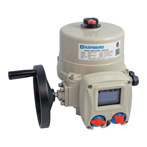
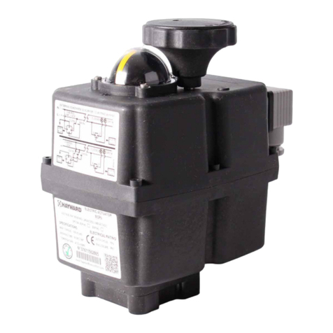
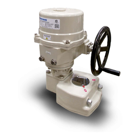
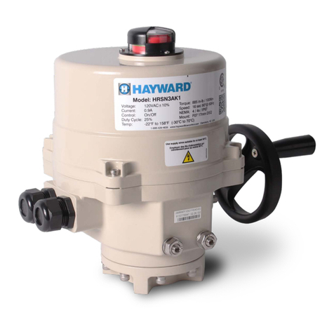
The HRSN3 Series actuators ending in “20” or in “2X” have an internal battery backup system and are quarter-
turn industrial electric actuators designed to operate valves and dampers in municipal, heavy commercial
or industrial applications. These units are NEMA 4/4X, IP67 rated, and feature on/off or proportional control
versions to interface to most eld control signals. The HRSN3 Series with battery backup operate on 24vac or
24vdc power supplies. Hayward offers 120v and 230v transformers packaged in stainless steel wall mounted
enclosures sized to provide the required power for the actuator and the battery system.
The battery pack and charge controller are housed in a side-mounted enclosure that is integral to the actuator
lower housing. Wiring of the actuator and battery system is completed through access to a single terminal
location. The battery system is designed to provide a minimum of two years of eld service (depending on
application and actual conditions of use). The battery pack is eld replaceable.
Notice: HRSN3 Series actuators are fully assembled, calibrated and tested prior to leaving our factory. In most cases, after
you have mounted the actuator to your device, you should be able to operate the actuator from fully CLOSED (CW) to fully
OPEN (CCW) and back again, and nd that no adjustments are needed. The assembly can be put into service immediately.
However, should it be necessary to make adjustments to the end-of-travel positions to overcome any device related issues
(i.e. valve shaft incorrectly timed to the drive stem), the procedures outlined below should be followed to put the assembly
into service. Note that there is a maximum adjustment range of +/- 3° at each end of travel.
Pages 10-11 - Travel limits for CW (CLOSED) & CCW (OPEN) positions, HRSN3 Series
Page 12 - Auxiliary switch cams for CW & CCW positions, HRSN3 Series
TABLE OF CONTENTS
HRSN3FS Series
Battery Backup
ACTUATOR OPERATIONAL CONCEPTS
Back to TOC
