Hayward AquaVac 500 User manual
AquaVac 500 Troubleshooting Guide
© 2014 Hayward Industries Inc.
®

Table of Contents
Safety Precautions Page 1
Service Tools Page 2
Power Supply Page 3
Motor Unit Page 4
Filter Removal & Replacement Pages 5-7
Wheel and Tire Removal Page 8
Side Cover Removal Page 9
Drive Track & Pulley Bearing Removal Page 10
Drive Shaft Pulley Removal Page 11
Wheel Tube & Drive Wheel Removal Page 12
Wheel Tube Brush Page 13
Power Cord Removal & Installation Pages 14-15
Motor Box Removal Pages 16-17
Power Supply and Flotation Cord Testing Pages 18-19
Troubleshooting Pages 20-23
Caddy Cart Assembly Pages 24-25
Safety
!
Page 1
• Always place the machine in the water before connecting it to the electrical supply.
• Always connect the power supply to an approved GFCI, ground fault circuit interrupter.
• Do not handle machine while it is plugged into the electrical supply.
• Do not use an extension cord.
• Immediately remove the cleaner from the water after cleaning.
• Never allow swimmers in the pool while the cleaner is operating.
• Never allow plug or power supply unit to enter pool.
• Keep the power supply unit a safe distance from the pool edge and water.
• Keep the power supply unit dry and away from rain or other water spray.

Pin Removal Tool
Torx Driver
T10 & T20
Torx Bit
T10 & T20
Spanner Tool
Service Tools
Torque Driver
Flat Head &
Phillips Head
Screwdrivers
(not shown)
Page 2

Power Supply Control
On/Off Power Button
Cord Assembly w/Swivel
(To Cleaner)
Page 3
Power Cord
(To GFCI Outlet)
Cleaner
Mode
Button
Cleaner
Schedule Button
Power Indicator Lights
Cleaning
Cycle
Mode
Lights
Cleaning
Schedule
Mode
Lights
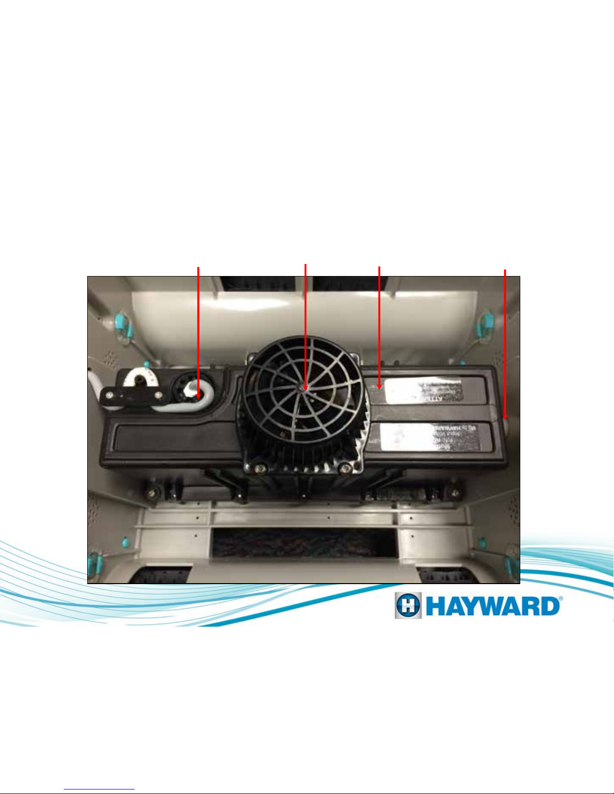
Motor Unit
Motor output shaft.
Drive end.
Motor assembly
Cord to Power
Supply
Impeller
Cover
Top view with filter assembly removed.
Page 4
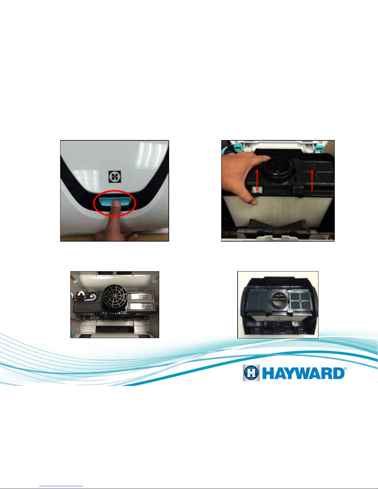
Filter Removal
Step 1: Press Dome Button
to lift Dome for filter removal.
Page 5
Filter Bucket Housing removed Filter Bucket Housing
Step 2: Lift to remove Filter
Bucket Housing.
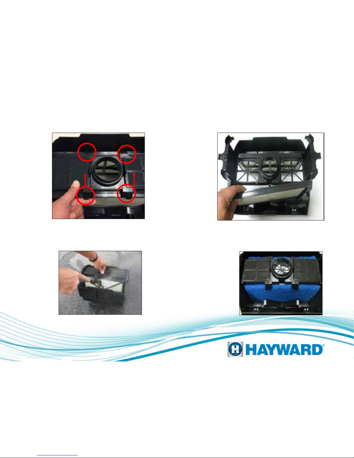
Filter Removal
Page 6
Note: Elements can be cleaned by gently spraying
with a garden hose. Be careful not to use high
pressure or this may damage the element. Elements
can be cleaned within Filter Housing or after being
removed as shown in Step 4.
Spring cleanup filter
elements.
For temporary use
in heavy spring
cleaning.
Step 3: Open filter doors by unsnapping
and lifting up both filter door latches. Step 4: Lift filter cartridges out.
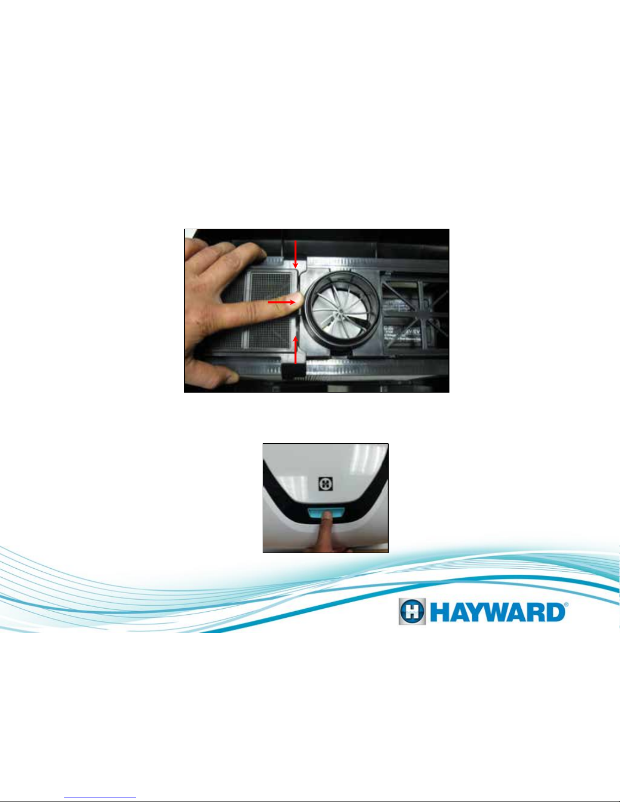
Filter Replacement
Hold both cartridges toward center. Push down cover and
press tab towards fan to lock cartridges in place.
Make sure cover snaps in place.
Page 7

Wheel and Tire Removal
Step 1: Remove snap retainers by
unsnapping from Side Cover.
Page 8
Step 4: Remove wheel from wheel bushing and cleaner base.
Step 3: Remove wedge
from wheel bushing
Step 2: Remove Side Cover from
Cleaner Base.
Other manuals for AquaVac 500
3
Table of contents
Other Hayward Swimming Pool Cleaner manuals


