Hazet 4934-3478/11 User manual

HAZET-WERK
HÖCHSTE TECHNOLOGIE IN DER WERKZEUGFERTIGUNG SEIT 1868
HIGHEST TECHNOLOGY IN TOOL MANUFACTURE SINCE 1868
Betriebsanleitung
Radnaben-Werkzeug Satz
Operating Instructions
Wheel Hub Bearing Tool Set
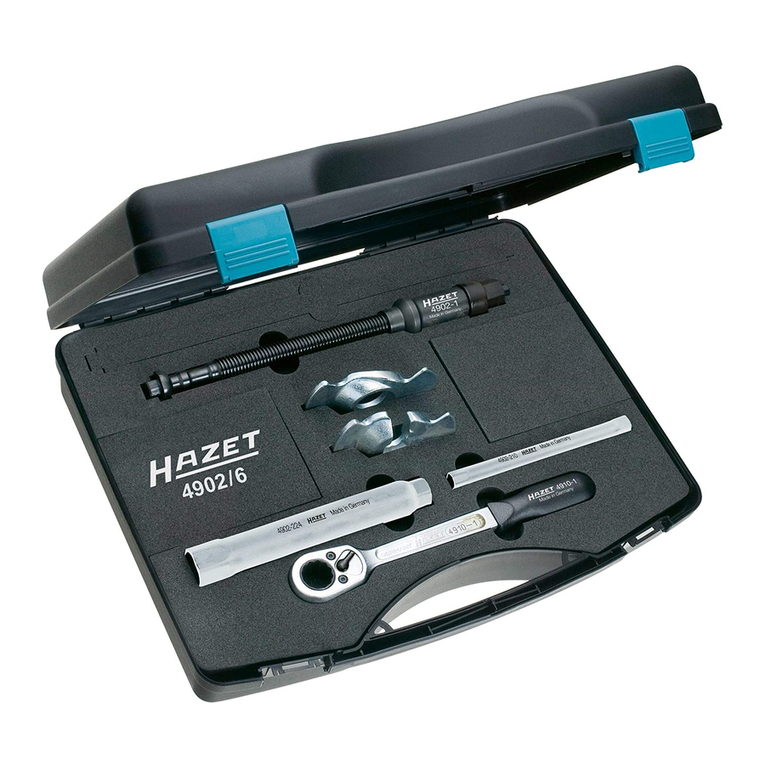
4934-3478/11
4934-3482/6
223555

2
HAZET-WERK - Hermann Zerver GmbH & Co. KG
} 10 04 61 • D-42804 Remscheid • Germany • [ +49 (0) 21 91 / 7 92-0
\ +49 (0) 21 91 / 7 92-375 (Deutschland) • \ +49 (0) 21 91 / 7 92-400 (International)
^ hazet.de • ] [email protected]
Ursprungsprache deutsch – original language: German – Langue d’origine: allemand
1 Zu Ihrer Information 3 ... 3
2 Zu Ihrer Sicherheit 4 ... 5
3 Aufbau und Funktion 6 ... 9
4 Wartung und Pflege 10 ... 10
5 Aufbewahrung und Lagerung 10 ... 10
6 Entsorgung 10 ... 10
1 For Your Information 11 ... 11
2 For Your Safety 12 ... 13
3 Design and Function 14 ... 17
4
Maintenance and Cleaning
18 ... 18
5 Storage 18 ... 18
6 Disposal 18 ... 18

3
Bei Betätigung nicht in die Vorrichtung greifen!
Vor jedem Gebrauch die Gewindespindel 4930-1 fetten!
1. Allgemeine Informationen
• Bitte stellen Sie sicher, dass der Benutzer
dieses Werkzeugs die vorliegende Betriebs-
anleitung vor der ersten Inbetriebnahme
gründlich durchgelesen und verstanden hat.
• Diese Betriebsanleitung enthält wichtige
Hinweise, die zum sicheren und störungs-
freien Betrieb Ihres Radnaben-Werkzeug
Satzes erforderlich sind.
• Zum bestimmungsgemäßen Gebrauch
des Radnaben-Werkzeug Satzes ge hört
die vollständige Beachtung aller
Sicherheitshinweise und Informationen in
dieser Betriebsanleitung.
• Bewahren Sie deshalb diese Betriebs-
anleitung immer bei Ihrem Radnaben-
Werkzeug Satz auf.
• Dieses Werkzeug wurde für bestimmte
An wendungen entwickelt. HAZET weist
ausdrücklich darauf hin, dass dieses
Werkzeug nicht verändert und/oder in einer
Weise eingesetzt werden darf, die nicht
seinem vorgesehenen Verwendungszweck
entspricht.
• Für Verletzungen und Schäden, die aus
un sach gemäßer und zweckentfremdeter
An wen dung bzw. Zuwiderhandlung gegen
die Sicherheitsvorschriften resultieren,
übernimmt HAZET keine Haftung oder
Gewährleistung.
• Darüber hinaus sind die für den Einsatz-
bereich des Gerätes geltenden Unfall-
verhütungs vorschriften und allgemeinen
Sicherheits bestimmungen einzuhalten.
2. Symbolerklärung
ACHTUNG: Schenken Sie diesen Symbolen
höchste Aufmerksamkeit!
Betriebsanleitung lesen!
Der Betreiber ist verpflichtet die
Betriebsanleitung zu beachten und
alle Anwender des Radnaben-
Werkzeugs gemäß der Betriebs-
anleitung zu unterweisen.
HINWEIS!
Dieses Symbol kennzeichnet Hin-
weise, die Ihnen die Hand habung
erleichtern.
WARNUNG!
Dieses Symbol kennzeichnet wich-
tige Beschreibungen, gefährliche
Beding ungen, Sicherheitsgefahren
bzw. Sicherheitshinweise.
ACHTUNG!
Dieses Symbol kennzeichnet
Hinweise, deren Nichtbeachtung
Beschädigungen, Fehlfunktionen
und/oder den Ausfall des Gerätes
zur Folge haben.
a
Zu Ihrer Information

4
Bei Betätigung nicht in die Vorrichtung greifen!
Vor jedem Gebrauch die Gewindespindel 4930-1 fetten!
1. Verantwortung des Betreibers
Das Gerät ist zum Zeitpunkt seiner
Entwicklung und Fertigung nach gel-
tenden, anerkannten Regeln der
Technik gebaut und gilt als betriebs-
sicher. Es können vom Gerät jedoch
Gefahren ausgehen, wenn es von nicht fach-
gerecht ausgebildetem Personal, unsachge-
mäß oder nicht bestimmungsgemäß, ver-
wendet wird. Jede Person, die mit Arbeiten
am oder mit dem Gerät beauftragt ist, muss
daher die Betriebsanleitung vor Beginn der
Arbeiten gelesen und verstanden haben.
• Betriebsanleitung stets in unmittelbarer Nähe
des Gerätes aufbewahren.
• Veränderungen jeglicher Art sowie An- oder
Umbauten am Gerät sind untersagt.
• Alle Sicherheits-, Warn- und Bedienungshin-
weise am Gerät sind in stets gut lesbarem
Zustand zu halten. Beschädigte Schilder
oder Aufkleber müssen sofort erneuert wer-
den.
• Angegebene Einstellwerte oder -bereiche
sind unbedingt einzuhalten.
2. Bestimmungsgemäße
Verwendung
Die Betriebssicherheit ist nur bei
bestimmungsgemäßer Verwendung
entsprechend der Angaben in der
Betriebsanleitung gewährleistet.
Neben den Arbeitssicherheits-Hinweisen in
dieser Betriebsanleitung sind die für den
Einsatzbereich des Gerätes allgemein gül-
tigen Sicherheits-, Unfall verhütungs- und
Umweltschutz-Vorschriften zu beachten und
einzuhalten.
Die Benutzung und Wartung von
Werkzeugen muss immer entsprechend
den lokalen staatlichen Landes- oder
Bundesbestimmungen erfolgen.
• Gerät nur in technisch einwandfreiem und
betriebssicherem Zustand betreiben.
• Sicherheitseinrichtungen immer frei erreich-
bar vorhalten und regelmäßig prüfen.
• Die Funktion des Radnaben-Werkzeugs ist
die Demon tage/ Montage von Radnaben-
Lager einheiten an Kfz. siehe Auf stel lung
rechts
• Das Radnaben-Werkzeug kann ausschließ-
lich von Hand betätigt werden.
• Jede über die bestimmungsgemäße Verwen-
dung hinausgehende und/oder andersar-
tige Verwendung des Radnaben-Werkzeug
Satzes ist untersagt und gilt als nicht bestim-
mungsgemäß.
• Ansprüche jeglicher Art gegen den Hersteller
und/oder seine Bevollmächtigten wegen
Schäden aus nicht bestimmungsgemäßer
Verwendung des Radnaben-Werkzeug
Satzes sind ausgeschlossen.
• Für alle Schäden bei nicht
bestimmungsgemäßer Verwendung haftet
allein der Betreiber.
• Vor jedem Gebrauch die Gewindespindel
4930-1 fetten.
• Während der Betätigung der Gewinde-
spindel nicht in die Abzieh-Vorrichtung
greifen, da sonst Verletzungs gefahr besteht.
• Zuordnung nach Fahrzeug-Hersteller:
Fahrzeugtypen mit Radlager x 78 mm
(mit Stehbolzen)
FORD
Focus 2 ab Baujahr 2004
C-Max Baujahr 2003-2007
ab Baujahr 2007
VOLVO
C 30 ab Baujahr 2006
C 70 2 Cabriolet ab Baujahr 2006
S 40 ab Baujahr 2004
V 50 ab Baujahr 2004
MAZDA
3 (BK)
1,4-1,6-1,6D TURBO ab Baujahr 2003
Ergänzungs-Satz 4934-3482/6 bis
x
82 mm
FORD
Focus 2 ab Baujahr 2007
Focus 2,5 RS ab Baujahr 2007
Focus 2,5 RS 500 ab Baujahr 2007
Mondeo 4 ab Baujahr 2007
b
Zu Ihrer Sicherheit

5
Bei Betätigung nicht in die Vorrichtung greifen!
Vor jedem Gebrauch die Gewindespindel 4930-1 fetten!
3. Gefahren
die vom Gerät ausgehen
Vor jeder Benutzung ist der Radnaben-
Werkzeug Satz auf seine volle Funk-
tions fähig keit zu prüfen.
Ist die Funk tions fähigkeit nach dem Ergebnis
dieser Prüfung nicht gewährleistet oder wer-
den Schäden festgestellt, darf das Radnaben-
Werkzeug nicht verwendet werden. Ist die volle
Funktions fähigkeit nicht gegeben und das
Radnaben-Werkzeug wird dennoch verwen-
det, besteht die Gefahr von erheblichen
Körper-, Gesund heits- und Sachschäden.
• Volle Funktionsfähigkeit ist gegeben, wenn:
- das Gerät leichtgängig ist
- das Gerät keine Beschädigung aufweist.
• Die Einzelteile dürfen nur in der vorge-
sehenen Zusammenstellung (Kapitel c
Aufbau und Funktion) eingesetzt werden.
• Durch das hohe Eigengewicht der Vorrich-
tung besteht bei der Demontage die Gefahr
von Verlet zungen. Während der Betätigung
der Gewinde-Spindel nicht in die Abzieh-
Vorrichtung greifen. Es ist darauf zu achten,
dass die Vorrichtung sicher gehalten wird.
• Bei der Betätigung ist auf enganliegende
Arbeits-Schutzkleidung zu achten.
• Alle Service- oder Reparaturarbeiten immer
durch Fachpersonal ausführen zu lassen.
Um die Betriebssicherheit auf Dauer zu
gewährleisten, dürfen nur Originalersatzteile
verwendet werden.
• Aus Sicherheitsgründen sind Verän der ungen
am Radnaben-Werkzeug strengstens unter-
sagt. Die Vornahme von Veränderungen am
Radnaben-Werkzeug führt zum sofortigen
Haftungs ausschluß.
b
Zu Ihrer Sicherheit

6
Bei Betätigung nicht in die Vorrichtung greifen!
Vor jedem Gebrauch die Gewindespindel 4930-1 fetten!
1. Technische Daten / Geräteelemente
Einzelteile
2. Lieferumfang
4934-3478/11 für Radlager d 78 mm
1
Bezeichnung
7
Maß
3
E4934-7801 Druckplatte 1 169 mm
4
D4934-7802 Druckscheibe zum Ausbauen 1 48 mm
5
F4934-8503 Druckbolzen 4 12 mm
6
B4934-7804 Stützringhälften zum Ausbauen 2 171 mm
7
A4934-7805 Stützringhälften zum Einbauen 2 171 mm
8
C4934-7806 Druckscheibe zum Einbauen 1 80 mm
9
Zylinderschrauben DIN EN ISO 4762
Güte 8.8 M 8 x 35
2M 8 x 35
4934-3482/6 für Radlager d 82 mm
1
Bezeichnung
7
Maß
4
D4934-8202 Druckscheibe zum Ausbauen 1 49 mm
6
B4934-8204 Stützringhälften zum Ausbauen 2 171 mm
7
A4934-8205 Stützringhälften zum Einbauen 2 171 mm
8
C4934-8206 Druckscheibe zum Einbauen 1 84,2 mm
3
E4934-7801* Druckplatte 1 167 mm
5
F4934-8503* Druckbolzen 4 12 mm
* zusätzlich notwendig!
* 4930-1 und 4930-2 Mechanische Spindel
1
und Spindelmutter
2
nicht im Satz enthalten
6 oder 7
9
5
3
1
*
2
*
4 oder 86 oder 7
c
Aufbau und Funktion

7
Bei Betätigung nicht in die Vorrichtung greifen!
Vor jedem Gebrauch die Gewindespindel 4930-1 fetten!
c
Aufbau und Funktion
3. Anwendung
Radnaben ausbauen
• Die 4 Druckbolzen
F
in die Aufnahmebohrungen der Druckplatte
E
einstecken.
Die Radnabe so drehen, dass ein Stehbolzen auf 12:00 Uhr steht.
• Die 2 Stützringhälften B seitlich zwischen die Radnabenflanschunterseite und das Lager-
gehäuse (Achskörper) einschieben und mit den 2 Zylinderschrauben M 8x35 fest verschrauben.
Danach den montierten Stützring um 180° zum Radnabenflansch verdrehen, so dass sich die 2
Axialzapfen a auf den Innenflächen der Stehbolzenköpfe c abstützen.
1
2
B
F
E
B
a
a
b
b
b b
c

8
Bei Betätigung nicht in die Vorrichtung greifen!
Vor jedem Gebrauch die Gewindespindel 4930-1 fetten!
c
Aufbau und Funktion
• Die Druckscheibe D auf die Spindelmutter 4930-2 aufstecken.
• Die Gewindespindel 4930-1 durch die Druckplatte
E
durchstecken.
• Die Gewindespindel 4930-1 mit der Druckplatte
E
und den 4 eingesteckten Druckbolzen
F
von außen auf die Radnaben/Lagereinheit so aufsetzen, dass die Druckbolzen
F
sich in die
Vertiefung b des Stützrings B stirnseitig abstützen. Gleichzeitig die Druckscheibe D mit der
Spindelmutter 4930-2 in die Lagerge häuse innenseite einführen und die Gewindespindel 4930-1
in die Spindelmutter 4930-2 eindrehen.
• Beim Erreichen des Kraftschlusses muss die Spindelmutter 4930-2 mit Hilfe eines
Schraubwerkzeuges (z.B. Ringschlüssel) gegengehalten werden.
• Nach der Demontage der Radnaben/Lagereinheit die Anbauteile demontieren!
Zylinderschraube
M 8 x 35
4930-2
C
F
E
4930-1
3
BD

9
Bei Betätigung nicht in die Vorrichtung greifen!
Vor jedem Gebrauch die Gewindespindel 4930-1 fetten!
c
Aufbau und Funktion
Radnaben/ Lagereinheit einbauen
Wichtig: Vor der Montage den Lagersitz reinigen.
Radlager und Sitz ausreichend einfetten.
Spindel und Spindelmutter ebenfalls ausreichend fetten.
• Die 4 Druckbolzen
F
in die Aufnahmebohrungen der Druckplatte
E
einstecken.
• Die Stützringhälften A seitlich zwischen die Radnabenflanschunterseite einschieben und mit
den 2 Zylinderschrauben M8 x 35 fest verschrauben.
• Die Gewindespindel 4930-1 mit der Druckplatte
E
und den 4 eingesteckten Druckbolzen
F
von außen auf die Radnaben/Lagereinheit so aufsetzen, dass die Druckbolzen
F
sich in den
Vertiefungen b des Stützringes A stirnseitig abstützen.
• Die Druckscheibe C auf die Spindelmutter 4930-2 aufstecken.
• Die Radlager/Radnabeneinheit mit der aufgesteckten Druckplatte
E
und der Spindel
4930-1 von außen in das Lagergehäuse einsetzen, gleichzeitig die Druckscheibe C mit
der Spindelmutter 4930-2 in die Lagergehäuseinnenseite (Achskörper) einführen und die
Gewindespindel 4930-1 anschließend in die Spindelmutter 4930-2 eindrehen.
• Bevor die neue Radnaben/Lagereinheit eingezogen wird, muss sichergestellt sein, dass diese
Einheit, achsparallel und mittig zur Aufnahmebohrung des Lagergehäuses (Achskörper) ausge-
richtet ist. Wenn erforderlich, die Achssymmetrie durch axiale Krafteinleitung (Gummihammer)
auf die Stirnseite der Druckplatte am Druckbolzensitz herstellen.
A
4
4930-2
4930-1
EFC
Zylinderschraube
M 8 x 35

10
Bei Betätigung nicht in die Vorrichtung greifen!
Vor jedem Gebrauch die Gewindespindel 4930-1 fetten!
1. Wartung und Pflege
• Gerät stets sauber halten.
• Keine entfettenden Mittel oder Wasser ver-
wenden, um Korrosion zu vermeiden.
• Bei allen Rückfragen und Ersatzteil bestel-
lungen unbedingt die Artikelnummer des
Gerätes angeben.
• Überprüfung und Reparatur ist ausschließ-
lich durch Fachpersonal vorzunehmen.
Ihr Ansprechpartner für:
• Gewährleistung
• Wartung und Instandsetzung
ist der HAZET-Partner vor Ort
oder das HAZET Service-Center
d
Wartung und Pflege
2. Ersatzteile
• Nur Original-Ersatzteile des
Herstellers verwenden.
• Falsche oder fehlerhafte Ersatzteile können
zu Beschädigungen, Fehlfunktionen oder
Totalausfall des Gerätes führen.
• Bei Verwendung nicht freigege-
bener Ersatzteile verfallen sämtliche
Garantie-, Service-, Schadenersatz- und
Haftpflichtansprüche gegen den Hersteller
oder seine Beauftragten, Händler und
Vertreter.
1. Aufbewahrung / Lagerung
Das Gerät ist unter folgenden
Bedingungen zu lagern und aufzu-
bewahren:
• Gerät nicht im Freien aufbewahren.
• Gerät trocken und staubfrei lagern.
• Gerät keinen Flüssigkeiten und aggressiven
Substanzen aussetzen.
• Lagertemperatur -10 bis +45°C.
• Relative Luftfeuchtigkeit max. 60%.
1. Entsorgung
• Zur Aussonderung, Gerät reinigen und
unter Beachtung geltender Arbeits- und
Umweltschutzvorschriften zerlegen.
Bestandteile der Wiederverwertung zufüh-
ren.
• Metallische Materialreste verschrotten
e
Aufbewahrung und Lagerung
f
Entsorgung

11
During operation do not reach into extractor device!
Lubricate the threaded spindle 4930-1 before each use!
a
For Your Information
1. General Information
• Please make sure that the user of this tool
reads carefully these operating instructions
and understands fully all information given
before it is used.
• These operating instructions contain impor-
tant advice that is necessary for a safe and
trouble-free operation of the tool set.
• For effective use of the tool set as intended,
it is essential that all safety and other infor-
mation given herein is adhered to.
• For this reason, always keep these operating
instructions together with the tool set.
• This tool set has been designed exclusively
for specific applications. HAZET emphazises
that any modification to the tool set and/
or use on an application not detailed to its
intended application is strictly forbidden.
• HAZET will not be liable for any injuries to
persons or damage to property originating
from improper application, misuse of the tool
set or a disregard of the safety instructions.
• Furthermore, the general safety regulations
and regulations for the prevention of acci-
dents valid for the application area of this
tool must be observed and respected.
2. Explanation of Symbols
ATTENTION: Please pay attention to these
symbols!
Read the Operating Instructions!
The owner of this tool is obliged to
observe the operating instructions
and should ensure all users of the tool
set to use it according to the informa-
tion given in this manual.
NOTICE!
This symbol marks advice which is
helpful when using the tool set.
CAUTION!
This symbol marks important speci-
fications, dangerous conditions,
safety risks and safety advice.
ATTENTION!
This symbol marks advice which if
disregarded results in damage,
malfunction and/or other functional
failure of the tool set.

12
During operation do not reach into extractor device!
Lubricate the threaded spindle 4930-1 before each use!
b
For Your Safety
• Any claims against the manufacturer and/
or its authorized agents because of damage
caused by improper use of the tool set will
be void.
• Any personal injury or material losses caused
by improper use are the sole responsibility
of the owner.
• Prior to each use lubricate the threaded
spindle 4930-1.
• During operation of the threaded spindle
do not reach into the extractor device oth-
erwise there is a risk of severe injury!
• Classification to vehicles:
Vehicles with wheel bearing x 78 mm
(with stud bolts)
FORD
Focus 2 since 2004
C-Max years 2003-2007
since 2007
VOLVO
C 30 since 2006
C 70 2 Cabriolet since 2006
S 40 since 2004
V 50 since 2004
MAZDA
3 (BK)
1.4 - 1.6 - 1.6D TURBO since 2003
Expansion Set 4934-3482/6 up to
x
82 mm
FORD
Focus 2 since 2007
Focus 2.5 RS since 2007
Focus 2.5 RS 500 since 2007
Mondeo 4 since 2007
1. Owner’s Liability
This tool set was developed and man-
ufactured according to the technical
norms and standards valid at the time
and is considered to be operationally reliable.
Nevertheless, the tool set can present a dan-
ger when it is not used as intended or in an
inappropriate way by non-qualified personnel.
Please make sure that any person using this
tool set or carrying out maintenance work
reads these operating instructions carefully
and understands fully all information given,
before using the tool.
• Keep the operating instructions together
with the tool set at all times.
• Any modification of the tool set is strictly
forbidden.
• All security advices, warning and operation
notices on the tool set have to be kept leg-
ible. Replace all damaged labels or stickers.
• All indications concerning setting values
and setting ranges must be observed.
2. Appropriate Use
Operational reliability can only be
ensured, if the tool is used as intend-
ed and in compliance with the indica-
tions given in the operating instructions.
In addition to the safety advice given in these
operating instructions, the general safety regu-
lations, regulations for the prevention of acci-
dents and for environmental protection being
valid for the application area of the tool set
have to be observed and respected.
Always ensure tools are used, inspected and
maintained in compliance with the respective
local, state, national or federal regulations.
• The tool set must only be used if it is in good
conditions.
• All safety equipment must always be within
reach and should be checked regularly.
• The tool set is intended for dismounting/
assembling wheel hubs / wheel bearings on
passenger cars. See list at the right side of
this page.
• The tool set is only intended for manual use.
• Any deviation from the intended use and/
or any misapplication of the tool set is not
allowed and will be considered as improper
use.

13
During operation do not reach into extractor device!
Lubricate the threaded spindle 4930-1 before each use!
b
For Your Safety
3. Dangers emanating from the tool
Before each use, check the tool set for
full functional efficiency. Do not use the
tool set if its functional efficiency cannot
be ensured or if damage is detected. If the tool
set is used, when it is not in full working order,
you risk severe injuries to persons and damage
to property.
• Full functional efficiency is ensured if:
– the device is smooth-running,
– the device is not damaged.
• Spare parts may only be used in the intend-
ed composition (chapter c Design and
Function).
• Due to the heavy weight of the device, there
is a risk of injury during dismounting. While
operating the threaded spindle do not reach
into the extractor device. Make sure that the
device is kept safe.
• While operating the tool, wear close-fitting
protective clothing.
• Any service or repair work must be carried
out by qualified personnel only. In order to
guarantee long term operational safety, only
spare parts of the manufacturer must be
used.
• For safety reasons any modification of the
tool set is strictly forbidden. Any modifica-
tion of the tool will result in immediate exclu-
sion from warranty and liability.

14
During operation do not reach into extractor device!
Lubricate the threaded spindle 4930-1 before each use!
c
Design and Function
1. Technical Information / Tool Parts
Spare parts
2. Included
4934-3478/11
for wheel bearing
d 78 mm
1
Designation
7
Dimens.
3
E4934-7801
Thrust plate
1169 mm
4
D4934-7802
Thrust washer for dismounting
148 mm
5
F4934-8503
Thrust pin
412 mm
6
B4934-7804
Thrust ring halves for dismounting
2171 mm
7
A4934-7805
Thrust ring halves for assembling
2171 mm
8
C4934-7806
Thrust washer for assembling
180 mm
9
Cylinder head screws DIN EN ISO 4762
Quality 8.8 M 8 x 35 2 M 8 x 35
4934-3482/6 for wheel bearing d 82 mm
1
Designation
7
Dimens.
4
D4934-8202
Thrust washer for dismounting
149 mm
6
B4934-8204
Thrust ring halves for dismounting
2171 mm
7
A4934-8205
Thrust ring halves for assembling
2171 mm
8
C4934-8206
Thrust washer for assembling
184,2 mm
3
E4934-7801*
Thrust plate
1167 mm
5
F4934-8503*
Thrust pin
412 mm
* additional equipment required!
* 4930-1 and 4930-2 Mechanical spindle
1
and Spindle nut
2
not included in set
6 or 7
9
5
3
1
2
4 or 86 or 7

15
During operation do not reach into extractor device!
Lubricate the threaded spindle 4930-1 before each use!
c
Design and Function
3. Application
Dismounting the wheel hub
• Insert the 4 thrust pins
F
into the receiving holes of the thrust plate
E
.
Turn the wheel hub until one stud bolt is on 12 o’clock position.
• Put the 2 thrust ring halves
B
laterally between the rear side of the wheel hub flange and the
bearing housing (axle body) and tighten firmly with the 2 cylinder head screws M 8X35. Turn the
installed thrust ring through 180° towards the wheel hub flange. Both axial pins a rest on the
inside surfaces of the stud bolt heads c.
1
2
B
F
E
B
a
a
b
b
b b
c

16
During operation do not reach into extractor device!
Lubricate the threaded spindle 4930-1 before each use!
c
Design and Function
• Put the thrust washer
D
onto the spindle nut 4930-2.
• Put the threaded spindle 4930-1 through the thrust plate
E
.
• Put the threaded spindle 4930-1 with the thrust plate
E
and the 4 inserted thrust pins
F
from
outside onto the the wheel bearing / wheel hub in a way that the thrust pins F rest on the recess
b of the thrust ring B. At the same time insert the thrust washer D with the spindle nut 4930-2
into the interior of the bearing housing and screw the threaded spindle 4930-1 into the spindle
nut 4930-2.
• Once the force closure has been reached, the spindle nut 4930-2 has to be retained with an
assembly tool for nuts and screws (e.g. box wrench).
• After dismounting the wheel hub bearing, dismount the mounted parts!
Cylinder head screw
M 8 x 35
4930-2
C
F
E
4930-1
3
BD

17
During operation do not reach into extractor device!
Lubricate the threaded spindle 4930-1 before each use!
c
Design and Function
Assembling the wheel hub bearing
Important: Prior to installation, make sure to clean the bearing seat.
Lubricate wheel bearing and bearing seat sufficiently.
Also lubricate spindle and spindle nut sufficiently.
• Put the 4 thrust pins
F
into the receiving holes of the thrust plate
E
.
• Insert the thrust ring halves
A
laterally between the rear side of the wheel hub flange and tight-
en firmly with the 2 cylinder head screws M 8 x 35.
• Put the threaded spindle 4930-1 with the thrust plate
E
with the 4 thrust pins F from outside onto
the the wheel bearing / wheel hub in a way that the thrust pins F rest on the recesses b of the
thrust ring A.
• Put the thrust washer
C
onto the spindle nut 4930-2.
• Put the wheel hub bearing with the attached thrust plate
E
and the spindle 4930-1 from out-
side into the bearing housing. At the same time insert the thrust washer
C
with the spindle nut
4930-2 into the interior of the bearing housing (axle body) and then screw in the spindle nut
4930-2.
• Before the new wheel hub bearing is assembled, it has to be ensured that it is axially parallel
and centric to the receiving hole of the bearing housing (axle body). If necessary, enforce the
axial symmetry by applying axial force (using a rubber hammer) onto the thrust plate’s front
side at the thrust pin seat.
A
4
4930-2
4930-1
EFC
Cylinder head
screw M 8 x 35

18
During operation do not reach into extractor device!
Lubricate the threaded spindle 4930-1 before each use!
d
Maintenance and Cleaning
1.
Maintenance and Cleaning
• Always keep tool clean.
• Do not use degreasing agents or water for
cleaning as they lead to corrosion.
• For any information or for spare part order-
ing, please always indicate article number of
the tool.
• Inspection and repair may only be carried
out by qualified personnel.
Your contacts for for:
• Warranty
• Maintenance and repair
are your local HAZET partners
2. Spare Parts
• Only use the manufacturer’s
original spare parts.
• Unsuitable or defective spare parts may
cause damage, malfunction or total failure of
the tool.
• The use of non approved spare parts will
void all warranty, service and liability claims
as well as all claims for compensation
against the manufacturer or its agents, dis-
tributors and sales representatives.
1. Storage
The tool has to be stored accord-
ing to the following conditions
• Do not store the tool outdoors.
• Keep the tool in a dry and dust-free place.
• Do not expose the tool to liquids or aggres-
sive substances.
• Storage temperature -10 up to +45°C.
• Relative air humidity max. 60%.
1. Disposal
• For disposal, clean tool and disassemble it
according to the regulations for work safety
and environmental protection. Components
can be recycled.
• Metal components can be scrapped.
e
Storage
f
Disposal

19
Notizen / Notes

223555 II. 09.2013/0.1 /be/MC
HAZET-WERK Hermann Zerver GmbH & Co. KG · } 10 04 61 · D-42804 REMSCHEID · GERMANY
[ +49 (0) 21 91 / 7 92-0 · \ +49 (0) 21 91 / 7 92-375 · ^ hazet.de · ] [email protected]
This manual suits for next models
1
Table of contents
Languages:
Other Hazet Tools manuals
Popular Tools manuals by other brands

Magswitch
Magswitch 400 Operation and instruction manual
WAGNER
WAGNER W 20 operating instructions

Matco
Matco Silver Eagle SE315B operating instructions

cam
cam GAB1 Series operating manual

Otto Ganter
Otto Ganter GN 865 operating instructions

Max
Max Rebartier RB398S Instruction manual and safety instructions

