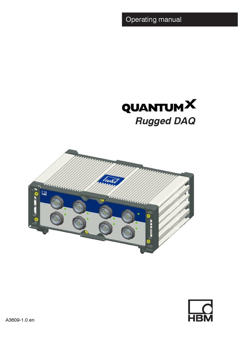
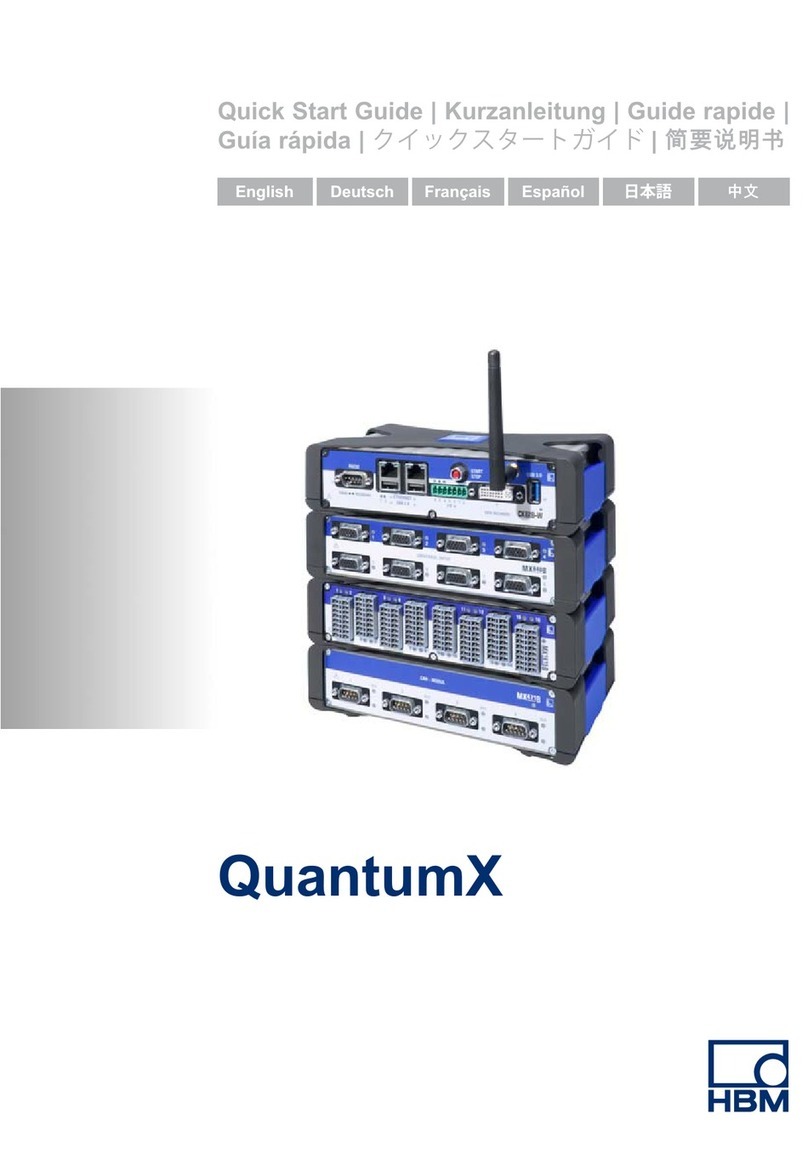
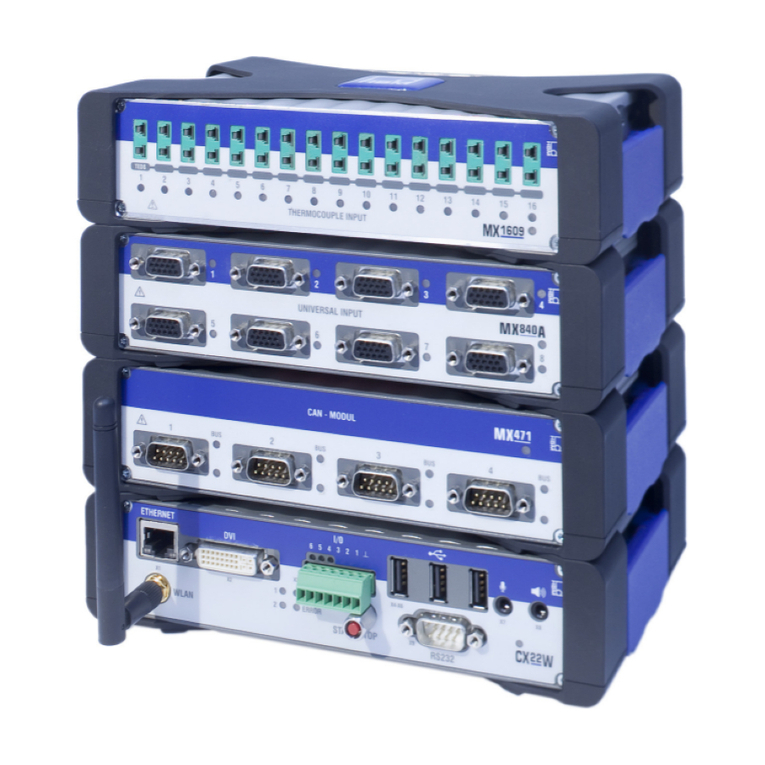
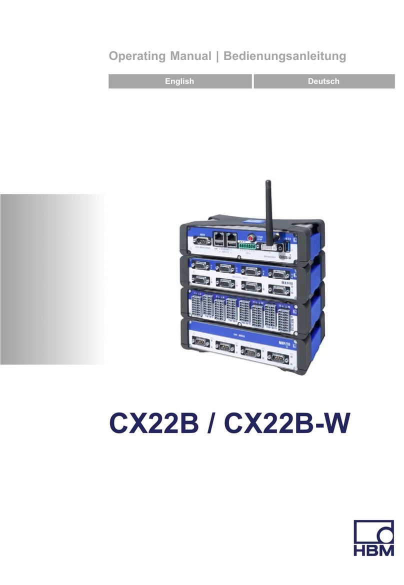
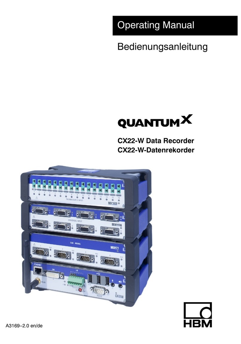
HBM QuantumX CX22 User manual

A3169‐1.0 en/de
Operating Manual
Bedienungsanleitung
QuantumX CX22‐W
CX22‐W Data Recorder
CX22‐W‐Datenrekorder

English Seite 3 - 42. . . . . . . . . . . . . . . . . . . . . . . . . . . . . . . . . . . . . . . . . . . . . . . . .
Deutsch Page 43 - 84. . . . . . . . . . . . . . . . . . . . . . . . . . . . . . . . . . . . . . . . . . . . . . .

3
QuantumX Data Recorder CX22‐W
A3169-1.0 en/de HBM
Contents Page
English
Safety information 5. . . . . . . . . . . . . . . . . . . . . . . . . . . . . . . . . . . . . . . . . . . . . . .
1 Markings used 8. . . . . . . . . . . . . . . . . . . . . . . . . . . . . . . . . . . . . . . . . . . . . . .
1.1 The markings used in this document 8. . . . . . . . . . . . . . . . . . . . . . . .
1.2 Symbols on the module and their meaning 9. . . . . . . . . . . . . . . . . .
2 Introduction 11. . . . . . . . . . . . . . . . . . . . . . . . . . . . . . . . . . . . . . . . . . . . . . . . .
3 CX22‐W connections 12. . . . . . . . . . . . . . . . . . . . . . . . . . . . . . . . . . . . . . . . .
4 Changing the CompactFlash card 14. . . . . . . . . . . . . . . . . . . . . . . . . . . . .
4.1 Procedure for removing the CF card 14. . . . . . . . . . . . . . . . . . . . . . . .
4.2 Procedure for inserting the CF card 15. . . . . . . . . . . . . . . . . . . . . . . .
5 Connecting the CX22‐W Data Recorder 16. . . . . . . . . . . . . . . . . . . . . . . .
5.1 Operation with monitor and keyboard/mouse 16. . . . . . . . . . . . . . . .
5.2 Connecting to a PC 17. . . . . . . . . . . . . . . . . . . . . . . . . . . . . . . . . . . . . .
5.3 Connecting QuantumX modules 17. . . . . . . . . . . . . . . . . . . . . . . . . . .
5.4 Connecting other devices 18. . . . . . . . . . . . . . . . . . . . . . . . . . . . . . . . .
6 Connecting a PC with the CX22‐W Data Recorder 19. . . . . . . . . . . . . . .
6.1 Direct connection of PC and CX22‐W 19. . . . . . . . . . . . . . . . . . . . . . .
6.2 Connecting the CX22‐W and PC via a network 21. . . . . . . . . . . . . .
6.3 Connection via WLAN (CX22‐W only) 23. . . . . . . . . . . . . . . . . . . . . .
6.3.1 Preparing the CX22‐W for WLAN connections 23. . . . . . . . .
6.3.2 Preparing the CX22‐W for an existing WLAN
(Access Point) 24. . . . . . . . . . . . . . . . . . . . . . . . . . . . . . . . . . . . .
6.3.3 Setting up connection via WLAN 24. . . . . . . . . . . . . . . . . . . . .
6.3.4 Preparing the CX22‐W for the Adhoc network 25. . . . . . . . . .
6.3.5 Preparing the PC for connection via an Adhoc network 26. .
6.3.6 Setting up a connection via WLAN and Adhoc network 27. .
7 The CX22‐W Data Recorder start screen 29. . . . . . . . . . . . . . . . . . . . . . .
8 Configure measurements with catman[AP 30. . . . . . . . . . . . . . . . . . . .
8.1 Set up device scan 30. . . . . . . . . . . . . . . . . . . . . . . . . . . . . . . . . . . . . . .
8.2 Create a DAQ (measurement) project 30. . . . . . . . . . . . . . . . . . . . . .
9 Configuring the CX22‐W for automatic measurements 33. . . . . . . . . .
10 Other CX22‐W connections 35. . . . . . . . . . . . . . . . . . . . . . . . . . . . . . . . . . .
10.1 Digital inputs and outputs 35. . . . . . . . . . . . . . . . . . . . . . . . . . . . . . . . .
10.2 START/STOP button 35. . . . . . . . . . . . . . . . . . . . . . . . . . . . . . . . . . . . .

QuantumX Data Recorder CX22‐W
4
A3169-1.0 en/deHBM
10.3 LED displays 36. . . . . . . . . . . . . . . . . . . . . . . . . . . . . . . . . . . . . . . . . . .
10.3.1 Module LED 36. . . . . . . . . . . . . . . . . . . . . . . . . . . . . . . . . . . . . . .
10.3.2 LEDs in the Ethernet connection 36. . . . . . . . . . . . . . . . . . . . .
10.3.3 Status LEDs for operating status 36. . . . . . . . . . . . . . . . . . . . .
10.3.4 Status LEDs for digital outputs 36. . . . . . . . . . . . . . . . . . . . . . .
10.3.5 LED for operating state of CF card 37. . . . . . . . . . . . . . . . . . .
10.4 Microphone input, loudspeaker output 37. . . . . . . . . . . . . . . . . . . . . .
10.5 USB connections 38. . . . . . . . . . . . . . . . . . . . . . . . . . . . . . . . . . . . . . . .
10.6 RS‐232 38. . . . . . . . . . . . . . . . . . . . . . . . . . . . . . . . . . . . . . . . . . . . . . . . .
11 System settings, update and restoration 39. . . . . . . . . . . . . . . . . . . . . . .
11.1 Changing system settings (Settings) 39. . . . . . . . . . . . . . . . . . . . . . . .
11.2 System restoration (Recovery) 39. . . . . . . . . . . . . . . . . . . . . . . . . . . . .
11.3 Updating catman[AP 41. . . . . . . . . . . . . . . . . . . . . . . . . . . . . . . . . . . .
11.4 Installing Windows software 41. . . . . . . . . . . . . . . . . . . . . . . . . . . . . . .
12 Waste disposal and environmental protection 42. . . . . . . . . . . . . . . . . .

5
QuantumX Data Recorder CX22‐W
A3169-1.0 en/de HBM
Safety information
Appropriate use
The QuantumX Data Recorders CX22 and CX22‐W (with WLAN) are to be
used exclusively for measurement tasks and directly related control tasks
within the application limits detailed in the specifications. Use for any purpose
other than the above is deemed to be non‐designated use.
In the interests of safety, the module should only be operated as described in
the Operating Manuals. It is also essential to comply with the legal and safety
requirements for the application concerned during use. The same applies to
the use of accessories.
The module is only to be installed and used by qualified personnel, strictly in
accordance with the specifications and the safety rules and regulations.
Each time, before commissioning the module, you must first run a project
planning and risk analysis that takes into account all the safety aspects of
automation technology. This particularly concerns personal and machine pro
tection.
Additional safety precautions must be taken in plants where malfunctions
could cause major damage, loss of data or even personal injury. In the event
of a fault, these precautions must establish safe operating conditions. This
can be done, for example, by mechanical interlocking, error signaling, etc.
NOTE
The module must not be connected directly to the power supply system. Sup
ply voltage 10 V ... 30 V (DC).
The supply connection and all other connections must be installed in such a
way that electromagnetic interference does not adversely affect device func
tionality (see also HBM Greenline Information, brochure i1577).
When devices are working in a network, these networks must be designed in
such a way that malfunctions in individual nodes can be detected and shut
down.
Automation equipment and devices must be designed in such a way that
adequate protection or locking against unintentional actuation is provided (e.g.
access checks, password protection, etc.).
Safety precautions must be taken both in terms of hardware and software, so
that a line break or other interruptions to signal transmission, e.g. via the bus
interfaces, do not cause undefined states or loss of data in the automation
QuantumX Data Recorder CX22‐W
6
A3169-1.0 en/deHBM
device. After making settings and carrying out activities that are password‐
protected, you must make sure that any controls that may be connected
remain in safe condition until the switching performance of the module has
been tested.
Ambient conditions on site
•Protect the module from direct contact with water.
•Protect the module from moisture or weather conditions such as rain,
snow, etc. The protection class under the IP standard DIN EN 60529 is
IP20.
•Please observe the permissible maximum ambient temperatures stated in
the specifications.
•Make sure that the side ventilation openings are not covered.
•The permissible relative humidity at 31°C is 80% (non condensing); linear
reduction up to 50% at 40°C.
•Do not expose the device to direct sunlight.
Conversions and modifications
The module must not be modified from the design or safety engineering point
of view except with our express agreement. Any modification shall exclude all
liability on our part for any resultant damage.
In particular, any repair or soldering work on motherboards (replacement of
components) is prohibited. When exchanging complete modules, use only ori
ginal parts from HBM.
The module is delivered from the factory with a fixed hardware and software
configuration. Changes can only be made within the possibilities documented
in the manuals.
Working safely
Error messages should only be acknowledged once the cause of the error is
removed and no further danger exists.
Qualified personnel
Qualified persons means persons entrusted with the installation, fitting, com
missioning and operation of the product who possess the appropriate qualific
ations for their function.
This includes people who meet at least one of the three following require
ments:
- Knowledge of the safety concepts of automation technology is a require
ment and, as project personnel, you must be familiar with these concepts.

7
QuantumX Data Recorder CX22‐W
A3169-1.0 en/de HBM
- As automation plant operating personnel, you have been instructed how to
handle the machinery. You are familiar with the operation of the modules
and technologies described in this documentation.
- As commissioning engineers or service engineers, you have successfully
completed the training to qualify you to repair the automation systems.
You are also authorized to activate, ground and label circuits and equip
ment in accordance with safety engineering standards.
General dangers of failing to follow the safety instructions
The QuantumX Data Recorders CX22 and CX22‐W are state‐of‐the‐art and
fail‐safe. The modules may give rise to dangers if they are inappropriately
installed and operated by untrained personnel. Any person instructed to carry
out installation, commissioning, maintenance or repair of the modules must
have read and understood the Operating Manuals and in particular the tech
nical safety instructions.
The scope of supply and performance of the modules only covers a small
area of measurement technology. In addition, equipment planners, installers
and operators should plan, implement and respond to the safety engineering
considerations of measurement technology in such a way as to minimize
remaining dangers. Prevailing regulations must be complied with at all times,
draw the attention of users to the remaining dangers connected with measure
ment technology.
Maintenance and cleaning
The modules are maintenance‐free. Please note the following points when
cleaning the housing:
•Before cleaning, disconnect all connections.
•Clean the housing with a soft, slightly damp (not wet!) cloth. Never use
solvent as this could damage the labeling or the housing.
•When cleaning, ensure that no liquid gets into the module or connections.

QuantumX Data Recorder CX22‐W
8
A3169-1.0 en/deHBM
1 Markings used
catmanis a registered trademark of HOTTINGER BALDWIN
MESSTECHNIK GMBH.
All trademarks and brands used in this document are trade names and/or
trademarks belonging to the respective product or the manufacturer/owner.
HOTTINGER BALDWIN MESSTECHNIK GMBH does not lay claim to any
other than their own trade names/trademarks.
1.1 The markings used in this document
Important instructions for your safety are specifically identified. It is essential
to follow these instructions, in order to prevent accidents and damage to prop
erty.
Safety instructions are structured as follows:
Signal word
Description of danger
Possible consequences of non‐compliance with specified measures
Measures to avoid/prevent the danger
Danger classes as per ANSI
Warning sign, signal word Significance
WARNING
Warns of a potentially dangerous situation
in which failure to comply with safety re
quirements can result in death or serious
physical injury.
CAUTION
Warns of a potentially dangerous situation
in which failure to comply with safety re
quirements can result in slight or moderate
physical injury.
NOTE The marking below warns of a situation in
which failure to comply with safety require
ments can lead to damage to property.

9
QuantumX Data Recorder CX22‐W
A3169-1.0 en/de HBM
The marking below draws your attention to important information about the
product or about handling the product.
Important
Important information
The marking below contains application tips or other information that is useful
to you.
Tip
Information/Application instructions
1.2 Symbols on the module and their meaning
Symbol:
Meaning: Read and note the data in this manual
Symbol:
Meaning: CE mark
The CE mark enables the manufacturer to guarantee that the product com
plies with the requirements of the relevant EC directives (the Declaration of
Conformity can be found on the HBM website at www.hbm.com under Sup
port -> HBMdoc).
Symbol:
Meaning: Statutory waste disposal mark
The electrical and electronic devices that bear this symbol are subject to the
European waste electrical and electronic equipment directive 2002/96/EC.
The symbol indicates that the device must not be disposed of as household
garbage, see also Chapter 12, Page 42.

QuantumX Data Recorder CX22‐W
10
A3169-1.0 en/deHBM
Symbol:
Meaning: USB connections, e.g. for keyboard, mouse, external
memory
Symbol:
Meaning: Microphone connection
Symbol:
Meaning: Loudspeaker connection
Symbol:
Meaning: Connection for earthing the housing
The connection must be connected to the grounded conductor potential.

11
QuantumX Data Recorder CX22‐W
A3169-1.0 en/de HBM
2 Introduction
This manual is intended to support you in setting the basic settings of your
QuantumX Data Recorder. The CX22 Data Recorder is available in two
versions: CX22 and CX22‐W. The CX22‐W version also has a WLAN module
with a WLAN antenna on the front of the module.
All measurement technology settings are implemented using the catmanAP
software, which has an extensive online Help.
This manual shows you:
•How to connect the module.
•What options are available for connecting to the module.
•How to connect to the module.
QuantumX modules are connected to the CX22‐W Data Recorder via
FireWire in the same way as is the case with other QuantumX modules,
alternatively, you can connect QuantumX modules via Ethernet.
The complete QuantumX documentation comprises:
•This operating manual
•QuantumX operating manual with pin assignments
•The QuantumX Data Recorder data sheet
•QuantumX module data sheets
•Online Help in the software
•catmanAP
•QuantumX Assistant
•Sensor database
•TEDS Editor
•Programming interface API (.NET/COM)
•LabVIEWtlibrary (VIs)
•DIAdemtdriver
•Examples for LabVIEWtand API (.NET/COM)

QuantumX Data Recorder CX22‐W
12
A3169-1.0 en/deHBM
3 CX22‐W connections
USB Microphone
Loudspeaker
Start/Stop button
RS‐232‐C
Digital I/Os
Status LEDs
Monitor
WLAN antenna
(CX22‐W only)
Ethernet
(Network)
Module LED
Fig. 3.1: CX22‐W connections on the front
CF card, type 1
Ejection button for CF
card
LED
Supply voltage
10 …30VDC
Grounding FireWire
Lock for CF card
Fig. 3.2: CX22‐W connections on the rear

13
QuantumX Data Recorder CX22‐W
A3169-1.0 en/de HBM
Ground connection and grounding
Lay signal and data leads separately from current‐carrying power lines. Cable
ducts made of sheet metal with an internal partition are ideal.
A potential equalization line must be laid if there are potential differences in or
to the connected measurement system (reference value: Highly flexible stran
ded wire, wire cross section 10mm2).

QuantumX Data Recorder CX22‐W
14
A3169-1.0 en/deHBM
4 Changing the CompactFlash card
Important
CompactFlash cards (CF cards) only have a limited number of write cycles,
i.e., they age (typically 1,000,000 write cycles). You should therefore check
the CF card regularly for errors in Windows and replace with a new card
where necessary. The service life of a CF card depends on the loading and
the manufacturer.
Ensure that a current, high quality CF card, type 1, CF version 4.1 is used
with at least 8 GBytes so that a high data rate can be achieved; older CF
cards usually have lower data rates. The card must be formatted with the
NTFS file system before insertion.
An 8 GByte CF card is included in the scope of delivery of the CX22‐W Data
Recorder.
4.1 Procedure for removing the CF card
NOTE
Do not replace the CF card when the CX22‐W is switched on.
This could damage the CX22‐W or the CF card or, if measurement data are
being recorded, this could cause all the data of the test to be lost.
Switch the CX22‐W off before replacing the CF card.
1. Undo the retaining screw for the CF card (Fig. 3.2 on Page 12). The
screw must not be removed, it should just be loosened.
2. Swivel the cover plate upwards to expose the slot for the CF card.
3. Use a blunt object, e.g. a ball‐point pen to press the ejection button on the
right in the CF card slot (Fig. 3.2).
4. Remove the CF card.
5. Read Section 4.2, this describes the insertion of the CF card. The
CX22‐W should not be operated without a CF card, as no data can be
stored.

15
QuantumX Data Recorder CX22‐W
A3169-1.0 en/de HBM
4.2 Procedure for inserting the CF card
The CF card must be formatted with the NTFS file system. You can carry out
this formatting with any PC that has a CF card slot or a CF card adapter and
uses Windows XP or higher.
NOTE
Switch the CX22‐W off before replacing the CF card. Otherwise the CX22‐W
or the CF card could be damaged or, if measurement data are being recorded,
this could cause all the data of the test to be lost.
1. Unless otherwise already implemented, undo the retaining screw of the
CF card slot (Fig. 3.2 on Page 12) and swivel the cover plate upwards.
The screw must not be removed, it should just be loosened.
2. Hold the CF card with the top facing upwards.
3. Slide the CF card into the slot until you feel a slight resistance at the end
when the contacts slide into the internal contact strip. The CF card must
disappear completely inside the slot.
4. Swivel the cover plate down until it engages in the protective casing
recess and the slot is covered.
5. Tighten the retaining screw by hand.

QuantumX Data Recorder CX22‐W
16
A3169-1.0 en/deHBM
5 Connecting the CX22‐W Data Recorder
Apply a supply voltage of 10V - 30V (DC) to the X103 connection (see
Fig. 5.1). Use a supply voltage with sufficient power if any QuantumX modules
connected to the CX22‐W also need to be supplied. The NTX001 power
packs available from HBM can supply a CX22‐W and two further modules.
Set up the connection to a PC first before connecting the QuantumX modules.
Implement the configuration either directly via the CX22‐W Data Recorder
(Section 5.1) or via a Remote Desktop Connection from your PC (Section 5.2
and Chapter 6). Then connect the QuantumX modules e.g. via FireWire with
the CX22‐W Data Recorder, see Section 5.3.
5.1 Operation with monitor and keyboard/mouse
This type of operation is the simplest. It does not require any configuration,
but you will need a monitor with digital input (DVI) and a mouse and keyboard
with USB connection.
Connect the mouse and keyboard to the USB sockets of the CX22‐W. The
monitor is connected with a commercial DVI monitor cable to the DVI socket
(see Fig. 3.1 on Page 12 for all connections). Connection via VGA is not pos
sible, not even with a DVI/VGA adapter connector as the leads required for
VGA are not assigned.
Switch on the power supply and wait until the boot process is complete and
the module is ready.
Important
The CX22‐W factory setting for the input language (keyboard layout) is EN
(English). If you connect a keyboard with a different layout, select Exit to
Windows in the start screen and then press Shift‐Alt or change the input lan
guage via the language bar in the task bar.
Set the location for your country if necessary using the Windows Control
Panel (“Regional and Language Options”). The setting influences, e.g. digit
settings and the time.
Set other settings via the start screen (CX22 Start Screen), see Chapter 7.
Tip
See also Chapter 9, Configuring the CX22‐W for automatic measurements,
from Page 33.

17
QuantumX Data Recorder CX22‐W
A3169-1.0 en/de HBM
5.2 Connecting to a PC
The CX22‐W Data Recorder is connected to the PC via Ethernet. There are
different variants, depending on your PC/network configuration, and the con
nection procedure depends on the variant:
1. CX22‐W and PC are connected directly via an Ethernet cable.
2. The CX22‐W Data Recorder is connected with an Ethernet network
(generally automatic assignment of network configuration via DHCP,
Dynamic Host Configuration Protocol).
3. The CX22‐W Data Recorder is connected via WLAN (CX22‐W only).
The initial configuration of a CX22‐W with WLAN must be implemented either
with monitor and keyboard (see Section 5.1) or via a connection with Ethernet
cable. You can then also activate the WLAN interface during this configuration
and enter the parameters for a WLAN connection.
Important
Wait approx. 1 minute after switching on the CX22‐W before setting up a con
nection so that the boot process is complete and the module is ready. Other
wise you may receive an error message that the device could not be found.
To facilitate setting up a CX22‐W connection with unknown settings, you can
use the HBM program “QuantumX Data Recorder Assistant”. The settings
required are described in the following chapter. If you already know the IP
address of the CX22‐W, you can also directly set up a Remote Desktop Con
nection (standard program in the Windows operating system). You can find
the Remote Desktop Connection program under All programs -> Accessor
ies (Windows XP: Programs -> Accessories).
5.3 Connecting QuantumX modules
Important
If you are already using QuantumX modules and want to connect them with a
CX22‐W Data Recorder, install the latest module firmware. If you want to add
new modules at a later date, please install the latest software on the CX22‐W
using the Recovery function, see Section 11.2 on Page 39. The latest soft
ware is always installed during restoring. You may receive a request, after
starting catmanAP, to update the firmware of older QuantumX modules.

QuantumX Data Recorder CX22‐W
18
A3169-1.0 en/deHBM
QuantumX modules are connected to the CX22‐W Data Recorder via
FireWire in the same way as is the case with other QuantumX modules: e.g.
1‐KAB269‐x, connection X100 of the CX22‐W to X101 on the first module, this
module with connection X102 to X101 on the next module, etc. Alternatively,
you can also connect all QuantumX modules via Ethernet to the CX22‐W. If
you have more than one module, you will require an Ethernet Switch.
In the configuration shown below, the supply voltage of the modules is looped
through FireWire (maximum 1.5A via FireWire; power consumption for a
module or the CX22‐W, see the Technical Data Section in the data sheet).
You can connect up to 12 modules via FireWire to the CX22‐W Data
Recorder, supply feed required for every 4 modules. The QuantumX operating
manual contains more detailed data on this.
10V ... 30VDC
FireWire connection
1‐Kab269‐x: Connection cable with various lengths (x m)
CX22(‐W)
Fig. 5.1: Connecting QuantumX modules to the CX22‐W Data Recorder
5.4 Connecting other devices
Only QuantumX modules can currently be connected to the CX22‐W Data
Recorder. If you want to connect other devices, e.g. MGCplus, please contact
HBM Support.

19
QuantumX Data Recorder CX22‐W
A3169-1.0 en/de HBM
6 Connecting a PC with the CX22‐W Data Recorder
If you know the IP address of the CX22‐W, you can also directly set up a
Remote Desktop Connection to this address. You can find the Remote
Desktop Connection program under All programs -> Accessories (Windows
XP: Programs -> Accessories).
Factory settings for the interfaces:
IP address Subnet mask
Ethernet 172.191.1.30 255.255.0.0
WLAN (deactivated) DHCP
Your settings:
IP address Subnet mask
Ethernet
WLAN
6.1 Direct connection of PC and CX22‐W
Procedure
1. Connect the PC and CX22‐W via an Ethernet cable, category CAT5 or
higher.
2. Install the program “QuantumX Data Recorder Assistant” from the Quan
tumX System CD.
3. Start the “QuantumX Data Recorder Assistant” program: Windows Start
button -> All programs -> HBM -> QuantumX Data Recorder Assist
ant (WindowsXP: Windows Start button -> Programs -> HBM ->
QuantumX Data Recorder Assistant).
4. Click on Find CX22.
5. The CX22‐W Data Recorder appears in the top list, the current
address(es) of the interface (WLAN only with CX22‐W) are also displayed
(Fig. 6.1).

QuantumX Data Recorder CX22‐W
20
A3169-1.0 en/deHBM
Fig. 6.1: Display in QuantumX Data Recorder Assistant after a network search
(example with connection via LAN)
6. The IP addresses and subnet masks of the PC interfaces are displayed in
the Settings of my computer section on the left side.
Depending on the configuration of your PC, both the PC and the CX22‐W
can be set to DHCP, then suitable addresses are set up (renewed)
between the two devices and you can continue next time with step 10.
Alternatively you can use permanent addresses for both devices. In this
case, you have two options: You can either change the PC address (Win
dows control panel) or the address of the CX22‐W. The latter is described
below.
7. Select the CX22‐W in the top list.
8. Click in the field TCP/IP‐Settings for CX22 on LAN and enter the
required IP address and subnet mask or select Use DHCP.
An address and subnet mask that lie within the address range of your PC
are automatically proposed, you can however change this proposal. Enter
an IP address in which the first three digit groups match the digit groups of
the PC and only the last digit group contains a different number between 1
and 254. The last digit group must not match the digit group in the PC!
Also see the example below.
9. Click on Apply and wait until the new address and are shown at the
top. The symbol indicates that a connection is possible.
10. If necessary, select the CX22‐W again in the top list and then click on
Remote connect using LAN.
This manual suits for next models
1
Table of contents
Languages:
Other HBM Data Logger manuals

HBM
HBM SomatXR MX Series User manual

HBM
HBM PMX User manual

HBM
HBM SomatXR MX Series User manual

HBM
HBM QuantumX User manual

HBM
HBM QuantumX User manual

HBM
HBM QuantumX CX22B User manual

HBM
HBM SomatXR MX Series User manual

HBM
HBM Operating Manual User manual

HBM
HBM eDAQXR-lite User manual

HBM
HBM SOMAT XR CX22B-R User manual