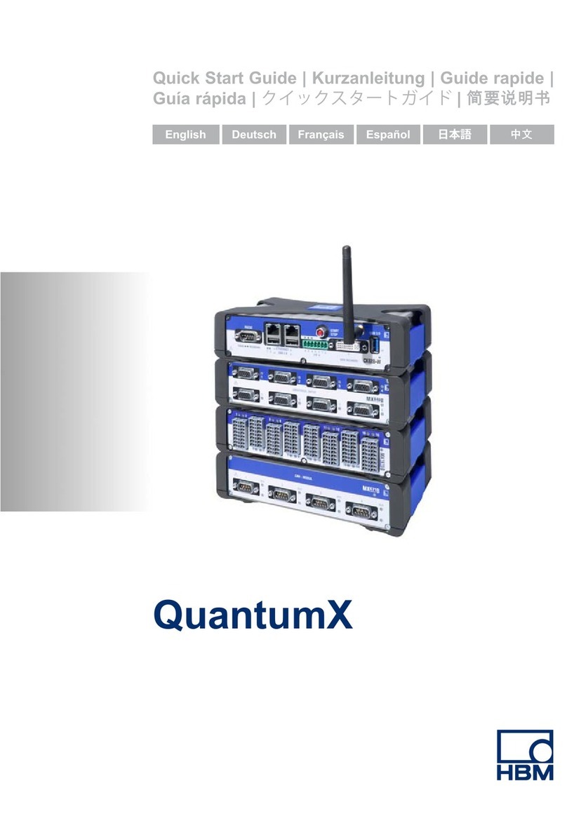
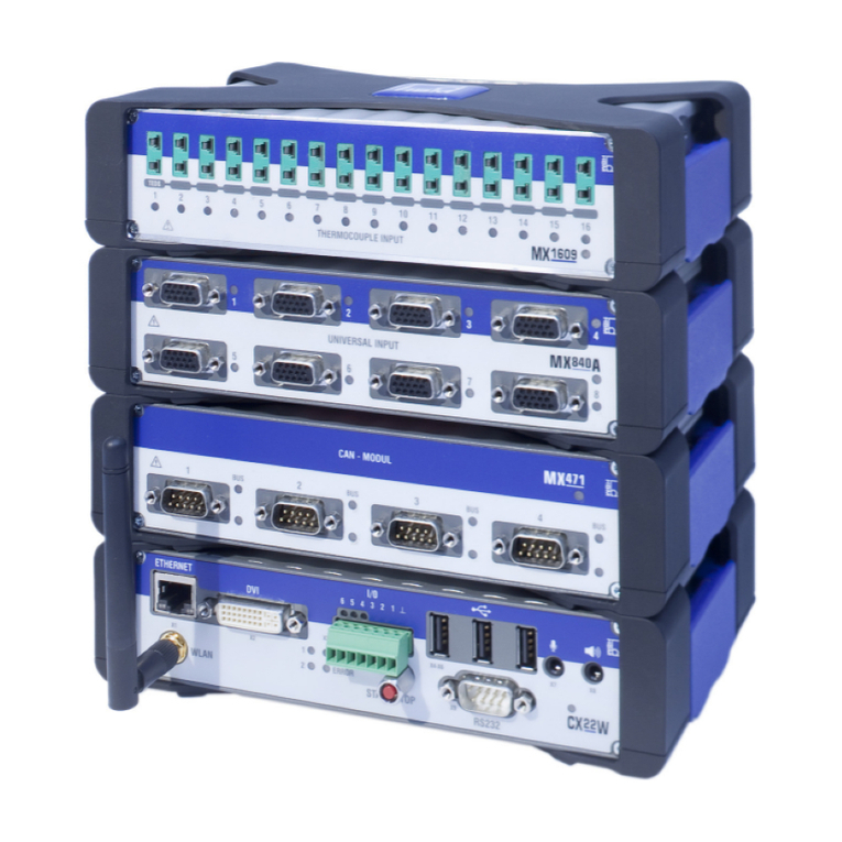
HBM QuantumX User manual

A2361-3.2 en/de
Quick Start Guide
Kurzanleitung

English Page 3−26. . . . . . . . . . . . . . . . . . . . . . . . . . . . . . . . . . . . . . . . . . . . . . . . .
Deutsch Seite 27−52. . . . . . . . . . . . . . . . . . . . . . . . . . . . . . . . . . . . . . . . . . . . . . .
Other trademarks and trade names may be used in this document to refer to
either the entities claiming the marks and names or to their products.
HOTTINGER BALDWIN MESSTECHNIK GMBH disclaims any proprietary
interest in trademarks and trade names others than its own.
Alle in diesem Dokument verwendeten Warenzeichen oder Marken weisen nur
auf das jeweilige Produkt oder den Inhaber des Warenzeichens oder der Marke
hin. HOTTINGER BALDWIN MESSTECHNIK GMBH erhebt damit keinen
Anspruch auf andere als die eigenen Warenzeichen oder Marken.

3
QuantumX
HBM
A2361-3.2 en/de
Content Page
Safety instructions 5. . . . . . . . . . . . . . . . . . . . . . . . . . . . . . . . . . . . . . . . . . . . . .
1 Introduction 10. . . . . . . . . . . . . . . . . . . . . . . . . . . . . . . . . . . . . . . . . . . . . . . . .
2 Connection options 11. . . . . . . . . . . . . . . . . . . . . . . . . . . . . . . . . . . . . . . . . .
2.1 Connecting module(s) via Ethernet 12. . . . . . . . . . . . . . . . . . . . . . . . .
2.1.1 Ethernet settings: adapt your module’s IP address 12. . . . .
2.1.2 Ethernet settings: adapt your PC’s IP address 18. . . . . . . . .
2.1.3 Integrating modules in an Ethernet Network 19. . . . . . . . . . .
2.2 Connecting modules via FireWire 21. . . . . . . . . . . . . . . . . . . . . . . . . .
2.3 Firmware update via Ethernet 23. . . . . . . . . . . . . . . . . . . . . . . . . . . . .

4Quantum
X
HBM A2361-3.2

5
QuantumX
HBM
A2361-3.2 en/de
Safety instructions
Appropriate use
The module and the connected transducers may be used for measurement
and directly related control tasks only. Any other use is not appropriate.
To ensure safe operation, the module may only be used as specified in the
operating manual. It is also essential to follow the respective legal and safety
regulations for the application concerned during use. The same applies to the
use of accessories.
Each time, before starting up the modules, you must first run a project
planning and risk analysis that takes into account all the safety aspects of
automation technology. This particularly concerns personal and machine
protection.
Additional safety precautions must be taken in plants where malfunctions
could cause major damage, loss of data or even personal injury. In the event
of a fault, these precautions establish safe operating conditions.
This can be done, for example, by mechanical interlocking, error signaling,
limit value switches, etc.
Safety rules
A module must not be connected directly to a power supply network.
The maximum permissible supply voltage is 10 V ... 30 V (DC).
The supply connection, as well as the signal and sense leads, must be
installed in such a way that electromagnetic interference does not adversely
affect device functionality (HBM recommendation: ”Greenline shielding
design”, downloadable from the Internet at http://www.hbm.com/Greenline).
Automation equipment and devices must be covered over in such a way that
adequate protection or locking against unintentional actuation is provided
(such as access checks, password protection, etc.).
When devices are working in a network, these networks must be designed in
such a way that malfunctions in individual nodes can be detected and shut
down.
Safety precautions must be taken both in terms of hardware and software, so
that a line break or other interruptions to signal transmission, such as via the
bus interfaces, do not cause undefined states or loss of data in the
automation device.

6QuantumX
HBM A2361-3.2 en/de
Conditions on site
For modules in IP20 protection class:
−Protect the modules from humidity or effects of the weather such as rain,
snow, etc.
−The permissible relative humidity at 31°C is 80% (non condensing); linear
reduction down to 50% at 40°C.
−Ensure that the ventilation openings on the sides are not covered.
For all modules:
−Do not expose the instrument to direct sunlight.
−Observe the maximum permissible ambient temperatures given in the
specifications.
Maintenance and cleaning
The modules are maintenance-free. Please note the following when cleaning
the housing:
−Before cleaning, disconnect the equipment completely.
−Clean the housing with a soft, slightly damp (not wet!) cloth. Never use
solvents, since these could damage the labelling on the front panel and the
display.
−When cleaning, ensure that no liquid gets into the module or connections.
General dangers of failing to follow the safety instructions
The module is a state of the art device and as such is failsafe. The module
may give rise to further dangers if it is inappropriately installed and operated
by untrained personnel. Any person instructed to carry out installation,
commissioning, maintenance or repair of the module must have read and
understood the Operating Manuals and in particular the technical safety
instructions.
Remaining dangers
The scope of supply and performance of the module covers only a small area
of measurement technology. In addition, equipment planners, installers and
operators should plan, implement and respond to the safety engineering
considerations of measurement technology in such a way as to minimize
remaining dangers. Prevailing regulations must be complied with at all times.
There must be reference to the remaining dangers connected with
measurement technology. After making settings and carrying out activities that
are password−protected, you must make sure that any controls that may be
connected remain in safe condition until the switching performance of the
module has been tested.

7
QuantumX
HBM
A2361-3.2 en/de
Working safely
Error messages should only be acknowledged once the cause of the error is
removed and no further danger exists.
Conversions and modifications
The module must not be modified from the design or safety engineering point
of view except with our express agreement. Any modification shall exclude all
liability on our part for any resultant damage.
In particular, any repair or soldering work on motherboards (replacement of
components is prohibited. When exchanging complete modules, use only
original parts from HBM.
The module is delivered from the factory with a fixed hardware and software
configuration. Changes can only be made within the possibilities documented
in the manuals.
Qualified personnel
Qualified persons means persons entrusted with the installation, fitting,
commissioning and operation of the product who possess the appropriate
qualifications for their function. This module is only to be installed and used by
qualified personnel, strictly in accordance with the specifications and the
safety rules and regulations.
This includes people who meet at least one of the three following
requirements:
•Knowledge of the safety concepts of automation technology is a
requirement and as project personnel, you must be familiar with these
concepts.
•As automation plant operating personnel, you have been instructed how to
handle the machinery and are familiar with the operation of the modules
and technologies described in this documentation.
•As commissioning engineers or service engineers, you have successfully
completed the training to qualify you to repair the automation systems. You
are also authorized to activate, to ground and label circuits and equipment
in accordance with safety engineering standards.
It is also essential to comply with the legal and safety requirements for the
application concerned during use. The same applies to the use of
accessories.

8QuantumX
HBM A2361-3.2 en/de
NOTE
The safety instructions in this document also apply to the NTX001 power
supply and the BPX001 active backplane.
In this manual, the following symbols are used to point out residual dangers:
Symbol: DANGER
Meaning: Maximum danger level
Warns of an imminently dangerous situation in which failure to comply with
safety requirements will result in death or serious bodily injury.
Symbol: WARNING
Meaning: Dangerous situation
Warns of a potentially dangerous situation in which failure to comply with
safety requirements can result in death or serious bodily injury.
Symbol: CAUTION
Meaning: Potentially dangerous situation
Warns of a potentially dangerous situation in which failure to comply with
safety requirements could result in damage to property or some form of
bodily injury.
Symbol:
Meaning: Electrostatic Sensitive Devices
Devices marked with this symbol can be destroyed by electrostatic discharge.
Please observe the precautions for handling electrostatic sensitive devices.
Symbol: On the equipment
Meaning: Observe information provided in the operating manual.

9
QuantumX
HBM
A2361-3.2 en/de
Symbols pointing out notes on use and waste disposal as well as useful
information:
Symbol: NOTE
Points out that important information about the product or its handling is being
given.
Symbol:
Meaning: CE mark
The CE mark enables the manufacturer to guarantee that the product
complies with the requirements of the relevant EC directives (the declaration
of conformity is available at http://www.hbm.com/hbmdoc).
Symbol:
Meaning: Statutory marking requirements for waste disposal
National and local regulations regarding the protection of the environment and
recycling of raw materials require old equipment to be separated from regular
domestic waste for disposal.
For more detailed information on disposal, please contact the local authorities
or the dealer from whom you purchased the product.

10 QuantumX
HBM A2361-3.2 en/de
1 Introduction
This quick start guide is intended to help you with the basic configuration of
your QuantumX system.
This quick start guide shows you how to
•Connect a module to a computer
•Implement the network settings for Ethernet TCP/IP or FireWire
•Update the module firmware
The complete QuantumX documentation comprises:
•This quick start guide
•QuantumX operating manual with pin assignments
•QuantumX operating manual CX27 Gateway
•Data sheets for the QuantumX modules
•Online help for
dQuantumX Assistant
dApplicationProgramming Interface (.NET/COM)
dLabViewlibrary (VIs)
dDiadem
dSensor database
dTEDS Editor
•Examples for LabView and API (.NET/COM)
The HBM software catmanis delivered with its own online help.

11
QuantumX
HBM
A2361-3.2 en/de
2 Connection options
The following chapters explain how to connect the modules and which
settings you must implement:
•Chapter 2.1 Connection to PC via Ethernet
•Chapter 2.2 Connection to PC via FireWire
Connection via EtherCAT to an automation system is described in the CX27
documentation.
NOTE
If you are already using QuantumX modules and want to add new
modules, please install the latest QuantumX software and the latest
module firmware (see Chapter 2.3). The latest PC software and the
module firmware can be found on the HBM website
(http://www.hbm.com/quantumx) in the area of Software/Firmware
downloads.

12 QuantumX
HBM A2361-3.2 en/de
2.1 Connecting module(s) via Ethernet
The modules can be
•connected directly to a PC (see chapter 2.1.1/2.1.2)
•integrated in a client server network (see chapter 2.1.3)
For synchronous measurement of all modules, they need to be connected
using FireWire cable 1−KAB269-x (connection X102 to X101 etc.).
Apply a supply voltage of 10V −30 V (DC) to connection X104. The supply
voltage is looped through to other modules via the FireWire cable
(max. 1.5 A, basic rule: Max. 3 modules on one supply). An additional voltage
source with the same voltage value is necessary for more than three modules.
The QuantumX modules support DHCP /APIPA1) automatic IP addressing.
The PC and the modules must be set to DHCP to enable this feature to be
used.
1) The Dynamic Host Configuration Protocol (DHCP) enables the network configuration to be assigned to
clients by a server. Automatic Private IP Addressing (APIPA) allows automatic configuration of network
interfaces, if no DHCP server is available.
2.1.1 Ethernet settings: adapt your module’s IP address
Adapt the module’s IP address as described below:
•Connect the module via an Ethernet crossover cable (e.g. 1-KAB239-2) to
the PC.
Newer PCs have an auto-crossover function, in this case you can use
patch cables (twisted pair, CAT5, preferably higher quality).
TCP/IP,
100 Mbps
Cross Over
1−KAB239−2
10 V ... 30 V DC
1−NTX001 oder
1−KAB271−3X104
X100
Fig.2.1: Multiple connection via Ethernet

13
QuantumX
HBM
A2361-3.2 en/de
NOTE
Ensure that your PC has a valid IP address.
Install and start up the latest QuantumX Assistant version on your PC.
(All screenshots shown in this quick start guide display the menus in the
operating system WindowsXP).
•Click on the icon (Find modules) or press the function key F4.
The next dialog window offers you the several options for network searching.
For the first startup we recommend:
•Search the whole network and select from the result (recommended
setting)

14 QuantumX
HBM A2361-3.2 en/de
Recommended
•If your modules are not yet displayed, click on the
button.
NOTE
The network connection can be influenced by:
wAn activated WiFi connection on your PC: Switch this connection off
and start the network search again
wThe use of a standard patch cable in a direct connection
(peer-to-peer)

15
QuantumX
HBM
A2361-3.2 en/de
If the module you have selected appears in black in the list, immediate
operation is possible.
If the module appears gray in the list, mark it and click on the ”Edit network
settings” button.
Check your settings and adjust if necessary as follows:
Adapt the IP address of the module in the following way:
•Activate DHCP/APIPA if you want automatic configuration as used with
your PC or Notebook
•Deactivate DHCP and enter the same subnet mask address as used with
your PC and change the IP address of your module so that it matches
communication (see example below)
Example: Manual IP setting −module side
Settings IP address Subnet mask
Module before 169.1.1.22 255.255.255.0
PC / Notebook 172.21.108.51 255.255.248.0
Module after 172.21.108.1 255.255.248.0
The first three digit groups of the PC and module IP addresses shall be the
same. The last digit group must be different (do not use DHCP with a direct
connection between PC and module).
The subnet mask address digit groups must be identical in the module and
PC!

16 QuantumX
HBM A2361-3.2 en/de
Module settings
PC settings
Module settings
PC settings
Automatic Configuration
Manual Configuration
255.255.248.0
172.21.108.1
Fig.2.2: Example settings for direct connection of one module

17
QuantumX
HBM
A2361-3.2 en/de
•Click on ”OK”
•Confirm the settings with the ”Yes” button, the module is then restarted with
the current settings.
After approx. 45 seconds click on the button.
The system LED of the module should now light up green, if not please check
your network settings again! If the network settings are ok, the module names
are shown in black.
•Mark the relevant modules by checking the relevant checkbox
•Confirm with ”OK” and you are now ready for your first measurement job
Connector pin-outs can be found in the operating manual.
Channel configuration can be found in the online help of the software.

18 QuantumX
HBM A2361-3.2 en/de
2.1.2 Ethernet settings: adapt your PC’s IP address
If you use your computer in various networks (IP address changes), but your
modules have a fixed IP address, you should use the ”Alternative
Configuration” in the TCP/IP properties (fixed IP address and subnet mask,
user-defined)!
Edit the PC settings as follows:
•Open the network connections (Start/Settings/Network connections).
•Mark your LAN connection with a right−click and select ”Properties” in the
context menu.
•Select the tab ”General” and mark the Internet (TCP/IP) under ”This
connection uses the following items”. Click on the ”Properties” button.
•In the tab ”Alternate Configuration”, select the option ”User-defined” and
enter your data in the ”IP address line” and ”subnet mask”.

19
QuantumX
HBM
A2361-3.2 en/de
Example: Manual IP setting −PC side
Settings IP address Subnet mask
Module before 169.1.1.22 255.255.255.0
PC / Notebook 172.21.108.51 255.255.248.0
PC / Notebook after 169.1.1.1 255.255.255.0
•Confirm twice with ”OK”.
In future, your computer will use the “Alternate Configuration” for the direct
connection.
2.1.3 Integrating modules in an Ethernet Network
•Activate the checkbox DHCP and click on ”OK”, the following confirmation
window then appears:
•Confirm the settings with the ”Yes” button, the module is then restarted with
the current settings.

20 QuantumX
HBM A2361-3.2 en/de
•After approx. 45 seconds click on the button.
The system LED of the module should now light up green, if not please check
your network settings again! If the network settings are ok, the module names
are shown in black.
•Mark the relevant modules by checking the relevant checkbox
•Confirm with ”OK”
Connector pin-outs can be found in the operating manual.
Channel configuration can be found in the online help of the software.
Other manuals for QuantumX
5
Table of contents
Languages:
Other HBM Data Logger manuals

HBM
HBM QuantumX CX22-W User manual

HBM
HBM SomatXR MX Series User manual

HBM
HBM QuantumX User manual

HBM
HBM QuantumX User manual

HBM
HBM PMX User manual

HBM
HBM SomatXR CX23-R User manual

HBM
HBM eDAQXR-lite User manual

HBM
HBM Operating Manual User manual

HBM
HBM GEN3i User manual

HBM
HBM QuantumX CX22B User manual