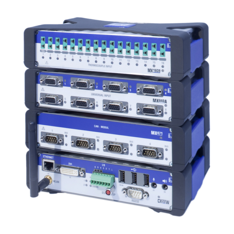
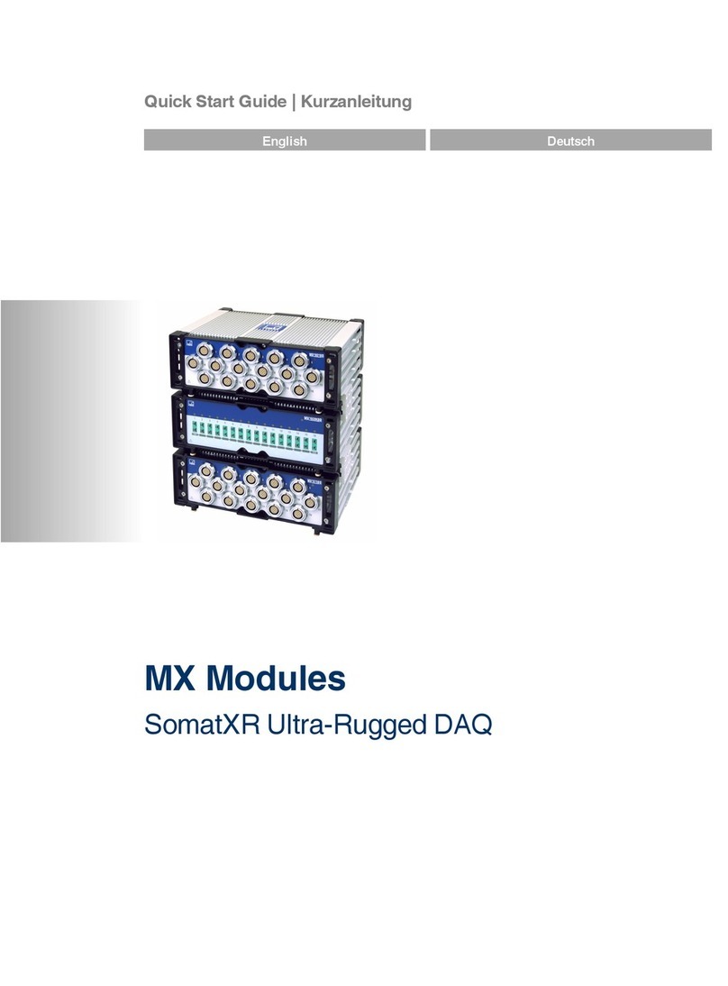
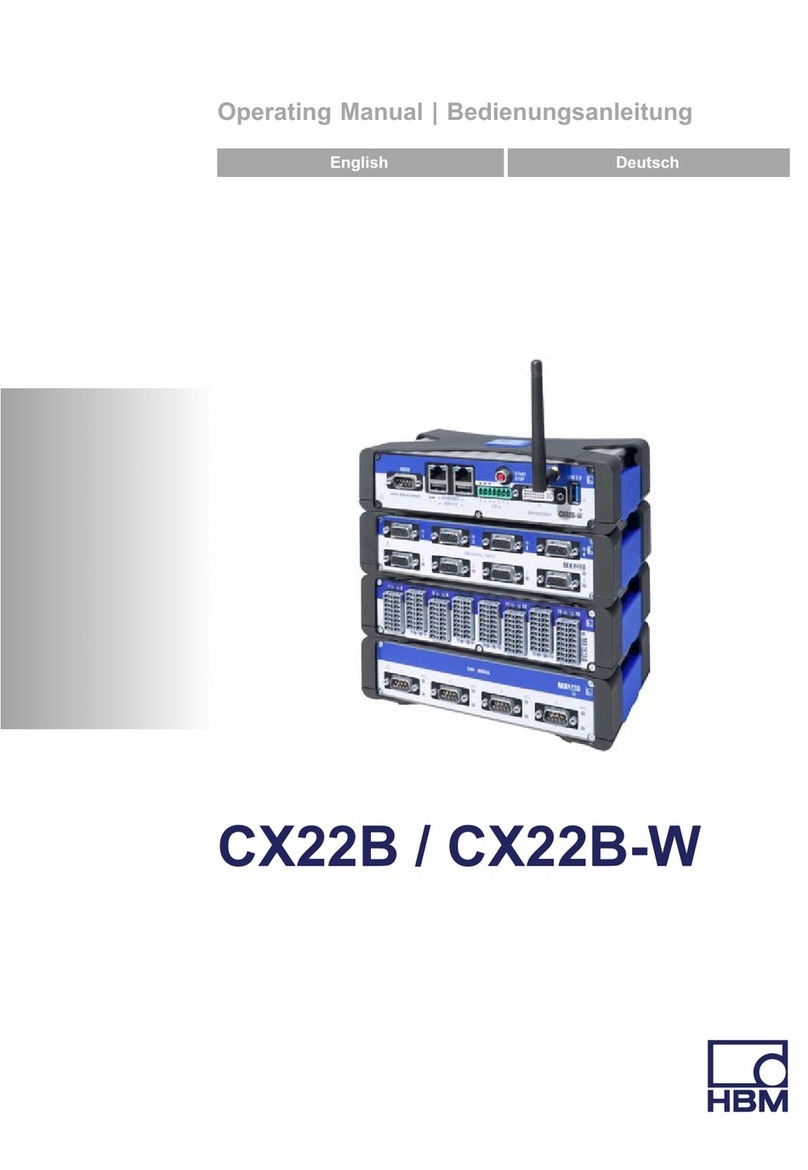
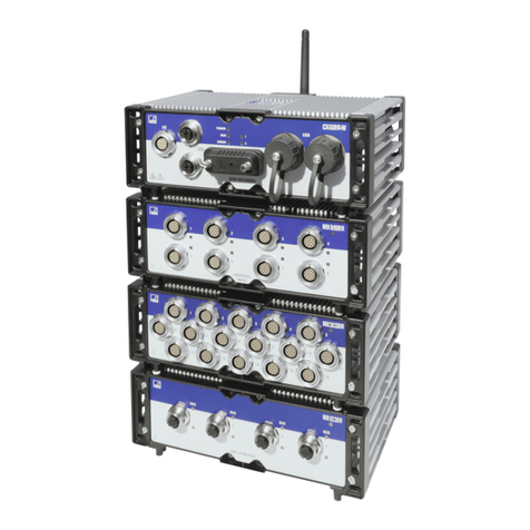
HBM QuantumX User manual

A3609-1.0 en
Operating manual
Rugged DAQ

d

3
HBMQuantumX Rugged DAQ
Content
1 Safety instructions 5......................................................
2 Introduction 11............................................................
2.1 About the QuantumX documentation 11.................................................
2.2 The QuantumX Rugged DAQ series 12.................................................
2.3 Digitalization and signal path 14........................................................
2.4 QuantumX Rugged DAQ module synchronization 15......................................
3 Software 19................................................................
3.1 QuantumX Assistant 19...............................................................
3.2 catmanAP 20......................................................................
3.3 Programming interface (API) 21........................................................
3.4 Firmware update via Ethernet 21.......................................................
3.5 TEDS Editor 24......................................................................
4 Housing 25................................................................
5 Connecting individual QuantumX modules with Rugged DAQ design 26.......
5.1 Connecting the supply voltage 26......................................................
6 Modules and transducers 27................................................
6.1 General information 27...............................................................
6.1.1 Shielding design 27...........................................................
6.1.2 Active transducer connection 28...............................................
6.1.3 TEDS 29....................................................................
6.1.4 Autocalibration / Autoadjustment 32............................................
6.2 MX840A-P universal amplifier 33.......................................................
6.2.1 MX840A-P pin assignment 35.................................................
6.2.2 MX840A-P status display 36...................................................
6.3 MX411-P highly dynamic universal amplifier 37...........................................
6.3.1 MX411-P pin assignment 38...................................................
6.3.2 MX411-P status display 39....................................................
6.4 MX460-P frequency measuring amplifier 40.............................................
6.4.1 MX460-P pin assignment 41...................................................
6.4.2 MX460-P status display 42....................................................
6.5 MX1609-P thermocouple amplifier 43...................................................
6.5.1 Thermocouple with TEDS functionality (RFID) 44.................................
6.5.2 MX1609-P status display 45...................................................
6.6 MX1601-P amplifier 46...............................................................
6.6.1 MX1601-P pin assignment 47..................................................

4
HBM QuantumX Rugged DAQ
6.7 Transducer connection 48.............................................................
6.7.1 Full bridge, SG 48............................................................
6.7.2 Full bridge, inductive 49.......................................................
6.7.3 Full bridge, piezoresistive 50...................................................
6.7.4 Half bridge, SG 51...........................................................
6.7.5 Half bridge, inductive 52......................................................
6.7.6 Potentiometric transducer 53..................................................
6.7.7 LVDT transducers 54.........................................................
6.7.8 Current-fed piezoelectric transducer 55.........................................
6.7.9 DC voltage sources 100 mV 58................................................
6.7.10 DC voltage sources 10 V or 60 V range 59......................................
6.7.11 DC current sources 20 mA 60..................................................
6.7.12 DC current sources 20 mA −current-fed 61......................................
6.7.13 Resistance 62...............................................................
6.7.14 Resistance thermometers Pt100, Pt1000 63.....................................
6.7.15 Frequency, differential, without directional signal 64...............................
6.7.16 Frequency, differential, with directional signal 65..................................
6.7.17 Frequency, single-pole, without directional signal 66..............................
6.7.18 Frequency, single-pole, with directional signal 67.................................
6.7.19 Encoder and pulse encoder, differential 68.......................................
6.7.20 Encoder and pulse encoder, single-pole 69......................................
6.7.21 SSI protocol 70..............................................................
6.7.22 Passive inductive encoder 71..................................................
6.7.23 PWM −Pulse width, pulse duration, period duration 72............................
6.7.24 PWM −Pulse width, pulse duration, period duration, single-pole 73.................
6.7.25 CANbus 74..................................................................
7FAQ 75....................................................................
8 Accessories 78............................................................
8.1 System accessories 80...............................................................
8.2 Voltage supply 80....................................................................
8.2.1 Power pack NTX002 80.......................................................
8.3 FireWire 81.........................................................................
8.3.1 FireWire cable (module to module; IP68) 81.....................................
8.3.2 Connection cable 82..........................................................
8.4 MX1609-P accessories 83............................................................
8.4.1 Thermo-connector with integrated RFID chip 83..................................
9 Support 84.................................................................

5Safety instructions
HBMQuantumX Rugged DAQ
1 Safety instructions
Appropriate use
A module with connected transducers is to be used exclusively for measurement tasks and
directly related control tasks. Use for any purpose other than the above is deemed to be
non-designated use.
In the interests of safety, the module should only be operated as described in the Operating
Manuals. It is also essential to comply with the legal and safety requirements for the
application concerned during use. The same applies to the use of accessories.
Before commissioning the module for the first time, you must first run a project planning and
risk analysis that takes into account all the safety aspects of automation technology. This
particularly concerns personal and machine protection.
Additional safety precautions must be taken in plants where malfunctions could cause major
damage, loss of data or even personal injury. In the event of a fault, these precautions
establish safe operating conditions.
This can be done, for example, by mechanical interlocking, error signaling, limit value
switches, etc.
Safety rules
The module must not be connected directly to the power supply system. Supply
voltage 10 V ... 30 V (DC).
The supply connection, as well as the signal and sensor leads, must be installed in such a
way that electromagnetic interference does not adversely affect device functionality (HBM
recommendation: “Greenline shielding design”, downloadable from the Internet at
http://www.hbm.com/Greenline).
Automation equipment and devices must be covered over in such a way that adequate
protection or locking against unintentional actuation is provided (e.g. access checks,
password protection, etc.).
When devices are working in a network, these networks must be designed in such a way that
malfunctions in individual nodes can be detected and shut down.
Safety precautions must be taken both in terms of hardware and software, so that a line
break or other interruptions to signal transmission, e.g. via the bus interfaces, do not cause
undefined states or loss of data in the automation device.
General dangers of failing to follow the safety instructions
The module is a state of the art device and as such is failsafe. The module may give rise to
dangers if it is inappropriately installed and operated by untrained personnel. Any person
instructed to carry out installation, commissioning, maintenance or repair of the modules
must have read and understood the Operating Manuals and in particular the technical safety
instructions.

6Safety instructions
HBM QuantumX Rugged DAQ
The scope of supply and performance of the modules only covers a small area of
measurement technology. In addition, equipment planners, installers and operators should
plan, implement and respond to the safety engineering considerations of measurement
technology in such a way as to minimize remaining dangers. On-site regulations must be
complied with at all times. There must be reference to the remaining dangers connected with
measurement technology. After making settings and carrying out activities that are
password-protected, you must make sure that any controls that may be connected remain in
safe condition until the switching performance of the module has been tested.
Working safely
Error messages should only be acknowledged once the cause of the error is removed and
no further danger exists.
Conversions and modifications
The module must not be modified from the design or safety engineering point of view except
with our express agreement. Any modification shall exclude all liability on our part for any
resultant damage.
In particular, any repair or soldering work on motherboards (replacement of components) is
prohibited. When exchanging complete modules, use only original parts from HBM.
The module is delivered from the factory with a fixed hardware and software configuration.
Changes can only be made within the possibilities documented in the manuals.
Outputs
Particular attention must be paid to safety when using the digital, analog or CANbus outputs
of a module. Ensure that status or control signals cannot initiate any actions that may pose a
danger to persons or the environment.
Qualified personnel
Qualified persons means persons entrusted with the installation, fitting, commissioning and
operation of the product who possess the appropriate qualifications for their function. This
module is only to be installed and used by qualified personnel, strictly in accordance with the
specifications and the safety rules and regulations.
This includes people who meet at least one of the three following requirements:
•Knowledge of the safety concepts of automation technology is a requirement and as
project personnel, you must be familiar with these concepts.
•As automation plant operating personnel, you have been instructed how to handle the
machinery and are familiar with the operation of the modules and technologies described
in this documentation.

7Safety instructions
HBMQuantumX Rugged DAQ
•As commissioning engineers or service engineers, you have successfully completed the
training to qualify you to repair the automation systems. You are also authorized to
activate, ground and label circuits and equipment in accordance with safety engineering
standards.
It is also essential to comply with the legal and safety requirements for the application
concerned during use. The same applies to the use of accessories.
NOTE
The safety instructions described here also apply to the power pack NTX002.

8Safety instructions
HBM QuantumX Rugged DAQ
The following symbols are used in this Operating Manual to point out remaining
dangers:
Symbol: DANGER
Meaning: Maximum danger level
Warns of an imminently dangerous situation in which failure to comply with safety
requirements will result in death or serious physical injury.
Symbol: WARNING
Meaning: Dangerous situation
Warns of a potentially dangerous situation in which failure to comply with safety
requirements can result in death or serious physical injury.
Symbol: CAUTION
Meaning: Possibly dangerous situation
Warns of a potentially dangerous situation in which failure to comply with safety
requirements could lead to damage to property, slight or moderate physical injury.
Symbol:
Meaning: Electrostatically sensitive components
Components marked with this symbol can be damaged beyond repair by electrostatic
discharge. Please observe the handling instructions for components exposed to the risk of
electrostatic discharge.
Symbol: On the device
Meaning: Take details in the operating manual into account

9Safety instructions
HBMQuantumX Rugged DAQ
Symbols for application and disposal instructions, as well as useful information:
Symbol: NOTE
Means that important information about the product or its handling is being provided.
Symbol:
Meaning: CE mark
The CE mark enables the manufacturer to guarantee that the product complies with the
requirements of the relevant EC directives (the Declaration of Conformity can be found at
http://www.hbm.com/hbmdoc).
Symbol:
Meaning: Statutory waste disposal mark
In accordance with national and local environmental protection and material recovery and
recycling regulations, old devices that can no longer be used must be disposed of separately
and not with normal household garbage.
If you need more information about waste disposal, please contact your local authorities or
the dealer from whom you purchased the product.

10 Safety instructions
HBM QuantumX Rugged DAQ
Conditions on site
The modules are suitable for applications in rough environments:
−Designed to degree of protection IP67 (dust, water)
−Extended temperature range from -35 to 80 °C
−Vibration / oscillation resistance up to 5 g
−Shock resistant up to 50 g
For all modules:
−Do not expose the modules to direct sunlight.
−Comply with the maximum permissible ambient temperatures stated in the specifications.
Maintenance and cleaning
The modules are maintenance-free. Please note the following points when cleaning the
housing:
−Before cleaning, disconnect the module from all connections.
−Clean the housing with a soft, slightly damp cloth. Never use solvent as this could
damage the labeling or the housing.
−Do not use high-pressure cleaners for cleaning.

11Introduction
HBMQuantumX Rugged DAQ
2 Introduction
2.1 About the QuantumX documentation
The QuantumX family documentation consists of
•A printed quick start guide for initial start up
•The data sheets in PDF format
•The operating manual for the standard series in PDF format
•This operating manual in PDF format
SThe operating manual for the EtherCAT / Ethernet-Gateways CX27 in PDF format
•A comprehensive Online help with index and easy search options which is available after
the installation of a software packet (e.g. QuantumX Assistant, catmanEASY).
Information about module and channel configuration can also be found here
These documents can be found
•On the QuantumX system CD supplied with the device
SAfter installation of the QuantumX Assistant on the hard drive of your PC
SUp-to-date versions are always available from our Internet site at
http://www.hbm.com/hbmdoc

12 Introduction
HBM QuantumX Rugged DAQ
2.2 The QuantumX Rugged DAQ series
The QuantumX Rugged DAQ series is a modular and universally applicable measurement
system. The modules can be individually combined and intelligently connected according to
the measurement task. The distributed operation makes it possible to position individual
modules close to the measuring points, resulting in short sensor lines.
The QuantumX Rugged DAQ series currently consists of the following modules:
SMX840A-P Universal amplifier
The module has 8 universal inputs and supports more than 14 transducer technologies.
SMX411-P Highly dynamic universal amplifier
The module has 4 universal inputs and supports the current transducer technologies.
SMX460-P Frequency measuring amplifier rotation specialist
The module has 4 digital timer inputs for connection of torque transducers (T10, T40),
incremental encoders, frequency signal sources.
SMX1609-P Thermocouple amplifier
The module has 16 inputs for type K thermocouples.
SMX1601-P Universal amplifier
The module has 16 individually configurable inputs for voltage or current measurement or
for connection of current-fed piezoelectric transducers.

13Introduction
HBMQuantumX Rugged DAQ
All modules have the following in common:
SLow voltage connection
SConfigurable Ethernet interface for data communication with an operating PC
S2 FireWire interfaces
−For optional voltage supply (note data sheet)
−For optional data communication with a PC
−For synchronization of the modules
−For internal measured data transmission
SStatus LEDs to display current module status
SA factory calibration certificate is stored on each amplifier, which can be read out by the
QuantumX Assistant
SAutoBoot (module configurations are retained)
With amplifiers, the following applies for each measurement channel:
SElectrical isolation (signal inputs/outputs, voltage supply, communication)
SConfigurable supply voltage for active sensors
SSupport for TEDS*) technology (read, write)
SConfigurable sampling rate
SConfigurable active digital filter (Bessel, Butterworth)
SConfigurable scaling (can also be saved in TEDS)
Sensors assigned using the sensor database can be calibrated via the channel and written
back into the sensor database.
*) TEDS = Transducer Electronic Data Sheet

14 Introduction
HBM QuantumX Rugged DAQ
2.3 Digitalization and signal path
Signal flow channel and generated signals
Each QuantumX measurement channel generates two signals.
These signals can be individually parameterized with a different data rate and filter.
Parameterization is easiest to implement with the “QuantumX Assistant” software (Signal
tab).
If several modules are connected together via the FireWire bus, signals can be sent in real
time (isochronous), e.g. from signal source to an output (analog, CAN or EtherCAT bus) or
for calculation. This isochronous real time operation is possible in parallel to the
asynchronous operation. The maximum data rate here is 4.8 kHz.
The data on runtimes and the filter tables of the respective data sheets must be used for the
calculation of runtimes from signal input to signal output.
Scaling
QuantumX Rugged DAQ supports the following scaling types:
•Two point (2-point / y=mx+b)
•Table (multi-point)
•Polynomial
The 16 channel modules MX1601-P and the modules MX411-P, MX460-P only support two
point scaling.

15Introduction
HBMQuantumX Rugged DAQ
2.4 QuantumX Rugged DAQ module synchronization
If measurement signals need to be referenced over time with each other for processing and
analysis, they must be recorded synchronously.
All QuantumX modules can be synchronized among themselves. This ensures simultaneous
measurement on all channels. All the analog-digital converter rates, measuring rates and
bridge excitation voltages are therefore also synchronized.
Synchronization methods:
Synchronization via FireWire
All the modules are synchronized automatically when they are connected via the FireWire
cable. This is the recommended method.
No CX27 module present in the system and no external synchronization source available:
The module with the highest serial number takes over the Master function.
CX27 module present in the system and no external synchronization source available:
If a CX27 module is connected, this automatically becomes the synchronization Master.
When starting the system, the system time is set once to the actual time.
If QuantumX modules alone are being used, internal synchronization is sufficient. However, if
synchronous measurements are to be performed by different measurement systems, an
external Master must be used for synchronization.
This is also a requirement if the QuantumX modules are a long distance away from one
another and a FireWire connection would be too complex.
Synchronization with external sources
In an external synchronization source is set, the module with the best synchronization quality
automatically becomes the master and synchronizes all modules connected via FireWire.
If several external sources are selected, the system decides according to the following
priorities:
1. EtherCAT
2. IRIG-B
3. NTP
Synchronization via EtherCAT
The CX27 Gateway supports the EtherCAT “Distributed Clocks” enhancement. In an
EtherCAT group, the time is distributed to all the EtherCAT nodes.
The CX27 module can be synchronized to the EtherCAT time. This will mean that all the
QuantumX module clocks are synchronized to this time.

16 Introduction
HBM QuantumX Rugged DAQ
Synchronization via an NTP server
Each QuantumX module can synchronize its internal clock with an NTP server. The NTP
time is distributed to the other modules via FireWire.
It is possible to achieve accuracies in the 100 µs range, although this depends on the
relevant Ethernet utilization.
Modules located close together should be synchronized via FireWire.
If the synchronization source for a module is changed to NTP, the system must be restarted
once. An NTP software package is included in the HBM software catmanEASY.
Parameter:
IP address of the NTP server
Threshold in µs, from which the time deviation to NTP time is tolerated
Further information about NTP can be found at http://www.ntp.org

17Introduction
HBMQuantumX Rugged DAQ
Synchronization via IRIG-B
IRIG-B is a standardized time coding.
To time-synchronize the QuantumX system, the digital or analog modulated time signal is
sent externally to any analog voltage input of the amplifier type MX840A-P (see assignment,
Chapter 6.2.1).
The B127 format uses an analog modulation. Connection is identical to that of a 10 V voltage
sensor.
The other formats are BCD-coded and must be connected analog to the sensor
“Frequencies single-pole, without directional signal”, see Chapter 6.7.17.
The amplifiers can acquire IRIG-B signals of type B000 to B007 and B120 to B127. All
modules connected via FireWire are also automatically synchronized. The coding includes
the time, year and optionally, the seconds of the day.
Comparison of synchronization mechanisms
Feature FireWire Ethernet (NTP) EtherCAT IRIG-B
Synchronization with
other device types
QuantumX only QuantumX
Rugged DAQ
MGCplus
Interrogators
Others
all EtherCAT
nodes
all IRIG-B
nodes
Max. distance between
QuantumX modules
5 m (40 m with FireWire
extender, 500 m via
fiber optics)
100 m (Ethernet) 100 m −
Number of modules to
be synchronized
24 unlimited CX27 required,
unlimited
unlimited
MX440A, MX840A
required,
Synchronization
accuracy
< 1 µs100 µs to 10 ms < 1 µs< 1 µs
Synchronization
settling time
Immediate approx. 2 h during first
start, approx. 10 min.
during restart
Immediate Immediate
Synchronization
master
Auto
1 Quantum module
external SyncMaster,
e.g. PC
external
SyncMaster
external IRIG-B
master
Voltage supply < 1.5 A, looped
through
− − −

18 Introduction
HBM QuantumX Rugged DAQ
Successful synchronization:
To achieve a precise reference over time, the applicable channels must be parameterized
with the same filter settings. No automatic runtime correction is carried out. The filter
runtimes are shown in the data sheet. After booting and successful synchronization, the
system LED shows green. If synchronization is disturbed, or not yet established, the system
LED shows orange.
Example: MX840A-P
System LED
Time format used:
Basis: 1.1.2000
Time stamp: 64 bit
32 bit seconds
32 bit fractions of a second, resolution (1/232)
These time stamps are appended to the measured values.
You can choose from several synchronization methods:
SSynchronizing via FireWire
SSynchronizing via EtherCAT (CX27)
SSynchronizing via NTP (Network Time Protocol) with FireWire
SSynchronizing via NTP without FireWire

19Software
HBMQuantumX Rugged DAQ
3 Software
The supplied QuantumX System CD contains a powerful software package consisting of the
QuantumX Assistant, programming libraries for .NET/COM, TEDS Editor, FireWire driver and
a program for module firmware updating. The software product catmanEASY is available
as an independent product package.
3.1 QuantumX Assistant
The HBM software “QuantumX Assistant” offers the following functions:
System:
•Create overview (modules, Host PC)
Modules:
•Search and configuration (e.g. TCP/IP communication), naming
•Reset to factory settings
•Read factory calibration certificate
•Analysis (information, status, log file)
•Save configuration to operating PC
Channels/sensors:
•Configuration (name, connection type, TEDS, semi-automatic assignment)
•Measurement (alphanumeric display)
•Open the TEDS editor and read/write to TEDS
•Activate/deactivate isochronous operation via FireWire
Individual signals:
•Set sampling rates and filters (type, cut-off frequency)
Measured values (Scope):
•Start/Stop continuous graphic measurements (time frames, trigger, zoom)
•Basic signal analysis (X-Y cursor)
•Record measurements
Functions and outputs:
•Generate new signals through mathematic functions (peak value, effective value, addition
and multiplication, rotation)
Sensor database:
•Output signals (scaled, filtered)
•Modify and expand existing sensor databases (e.g. own sensors, dbc data files)

20 Software
HBM QuantumX Rugged DAQ
3.2 catmanAP
The HBM “catmanAP” software is optimally suited for the following tasks:
•Setting the communication and measurement channels (integrated TEDS Editor and
extendable sensor database)
•Configuration of measurement or test tasks (channels, sampling rates, triggers,
comments, interactions)
•Setting up virtual online calculated channels (algebra, FFT, logic, SG rosette evaluation,
differential, integral, etc.)
•Setting up limit value or event monitoring (digital output activation, acoustic alarm,
logbook entry)
•Individual graphic representation options (strip chart, analog meter, digital or bar display,
tables, status LEDs, etc.)
•Diverse storage options (all data, cyclic, ring buffer, long-term measurements, etc.)
•Export of measured data in current data format (catmanBIN, Excel, ASCII, DIADEM,
MDF)
•Graphic analysis of acquired data
•Automation of measurement sequences (AutoSequence and EasyScript)
•Generating reports (with graphic displays, analyses, comments)
The software package consists of various modules:
SEasyMath for mathematical evaluation
SAutoSequence automates repeating measurement or analysis steps
SEasyPlan enables preparatory parameterization and configuration without amplifier
connection
SEasyScript is based on current VBA standard (Visual Basic for Applications) and enables
writing of own scripts for individual measurement tasks
Other manuals for QuantumX
5
Table of contents
Other HBM Data Logger manuals

HBM
HBM PMX User manual

HBM
HBM QuantumX User manual

HBM
HBM SomatXR MX Series User manual

HBM
HBM SomatXR MX Series User manual

HBM
HBM SomatXR CX23-R User manual

HBM
HBM QuantumX CX22-W User manual

HBM
HBM QuantumX CX22B User manual

HBM
HBM QuantumX CX22 User manual

HBM
HBM SomatXR MX Series User manual

HBM
HBM espressoDAQ DQ401 User manual