HBX SNO-0600 Snowmelt Control
Version 1.0.0
Page 4
We recommend all signal wiring to be a minimum of 18AWG shielded wire at a maximum of 500ft.
4. SENSOR INPUTS
11, 13: System Supply Sensor – Brass strap on sensor, to
be installed on the supply to the snow melt manifold
12, 13: Return Sensor – Brass strap on sensor, to be
installed on the return to the snow melt manifold.
15, 16: Outdoor temperature.
2. MODULATING OUTPUT
5,6: For modulating boiler or mixing device 0-10V DC
output
1. DEMAND OUTPUTS
1,2: Dry contact 24VAC max
3,4: Dry contact 24VAC max
3. DEMAND INPUTS
7,8: IDLE SLAB DEMAND INPUT Apply a snow melt
demand from a dry contact to initiate an Idle demand.
9,10: MELT SLAB DEMAND INPUT Apply a snow melt
demand from a dry contact to initiate an melt
demand.
6. BOILER CONTACT
1, 2: Boiler Contact: Boiler enable contact
3,4: Non-Applicable: This contact does not have any
functionality and may used in a future upgrade. Do
not install anything to this contact.
6. AUXILIARY OUTPUTS
5, 6: Aux 1 - Can be used as an system pump,
Floating action valve up, oating action valve down,
pump test, App
7, 8: Aux 2 – Can be used as an Injection pump,
system pump, Floating action valve up, oating
action valve down, pump test, App
9, 10: Aux 3 - Can be used as an system pump,
Floating action valve up, oating action valve down,
pump test, App
7. INPUT POWER
11, 12, 13: This input is to power the SNO-0600. 0.25
Amps at 120 VAC is required to power this device
5. SNOWMELT OPTICAL SENSOR
17, 18, 19, 20, 21: Snow Melt Sensor: Green (17), Red
(18), White (19), Black (20), Shield (21)
DO NOT CONNECT
POWER HERE
GR
POWER
120
13
N
L
1211
5A
1
Aux 1
5 6
1 2
Aux 2
7 8
2
5A
HBX SNO-0600 SNOW MELT CONTROL
1
8
7
2 3
109
4
Demand In
1
1211
2
13
Sensor 1
3
1514
4
16
Sensor 2
1
DEM 1
21
1 2
43
21
65
1
Demands
DEM 2 MOD
Boiler Output 5A
3
Aux 3
9 10
3
SNO-0600
Input Power
Class 2 Circuits
Class 2 Circuits
1
1817
2
19
3
20
4
21
Snow Sensor
1
Boil 1
1 2
1 2
N/A
3 4
2
5
SG PW TM S
Mod
Output
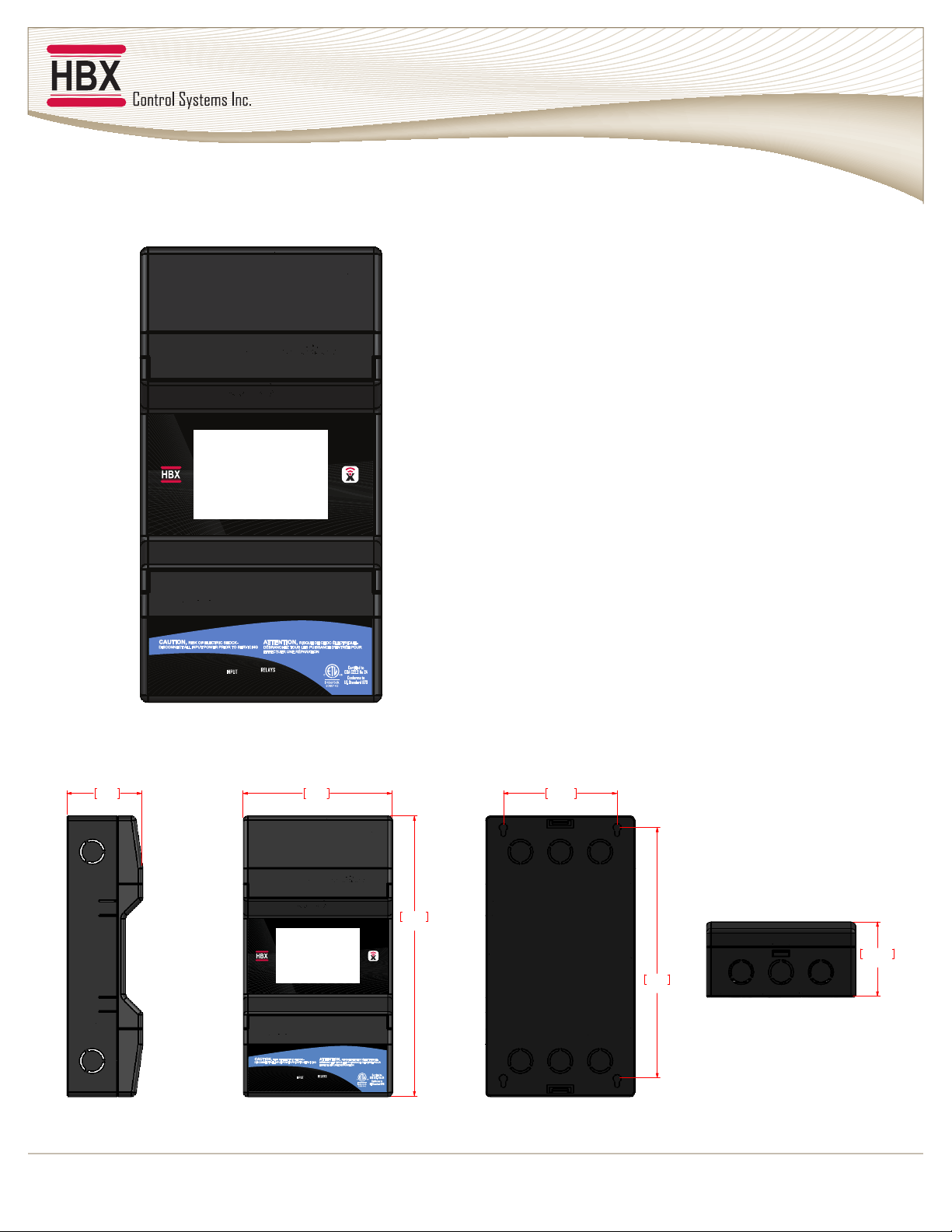
WIRING AND INSTALLATION
SNO-0600 Installation
The SNO-0600 is designed to be wall mounted or installed in a separate electrical enclosure. The
unit should be installed inside and protected from falling water and high humidity conditions.
With all the covers in place, it is designed to protect any individual from accidental electrical
shock. It is not suitable for installation in hazardous locations and should not be close to any
electromagnetic elds.
• Identify the four mounting holes on the SNO-0600, mark on the wall the desired location of
mounting
• Pre-drill, anchor and fasten four screws for mounting
• Hang SNO-0600 and fasten tight to desired locations
• Complete wiring connections in accordance with terminal locations