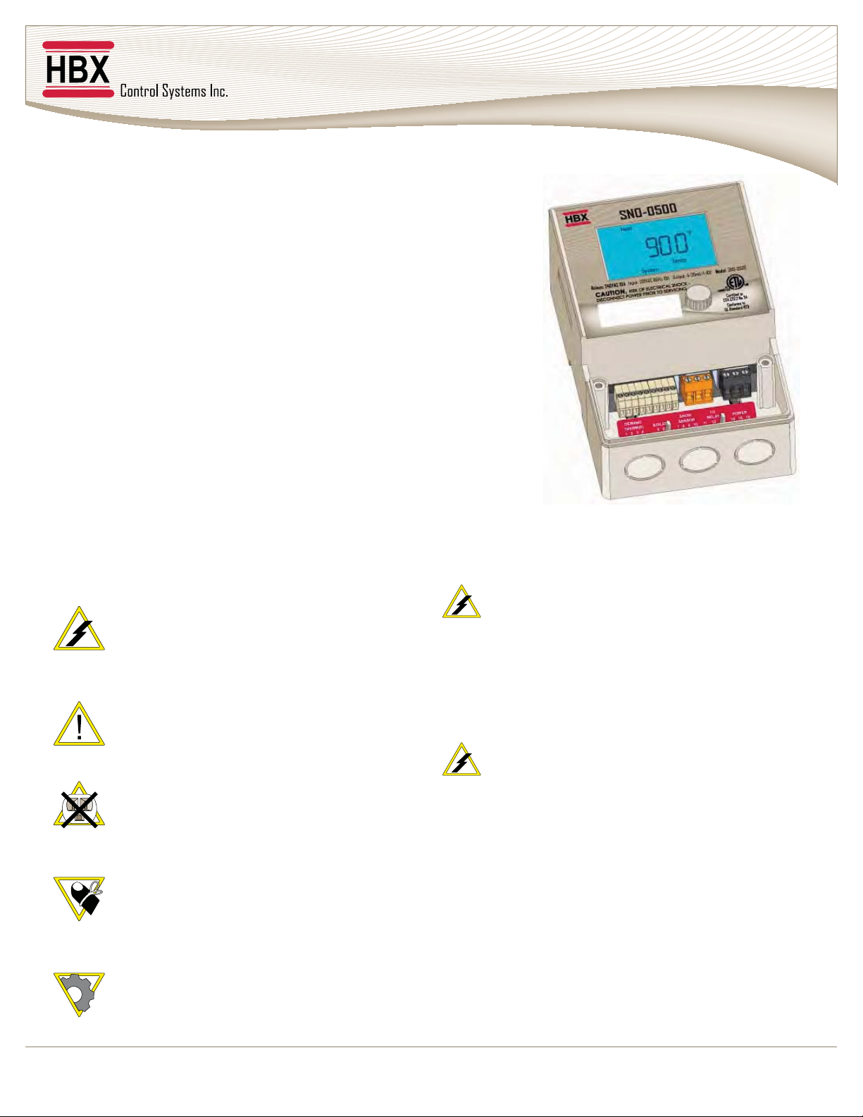
HBX SNO-0500 HVAC Control
Version 1.04
© HBX Control Systems Inc. 2012 Page 3
HBX SNO-0500 SNOWMELT CONTROLLER
INTRODUCTION
This manual will help with the installation, parameter setting,
troubleshooting and general maintenance requirements for the
controller. To guarantee the safe and reliable operation of this control,
and all warnings or caution directives prior to connecting to AC power.
and HVAC controls should attempt the installation of this equipment.
Incorrect wiring and installation will affect the warranty provided with
this unit. Wiring must be completed in accordance with the codes and
practices applicable to the jurisdiction for the actual installation.
The HBX SNO-0500 is a standalone snow melt control. Please consult
and install the heating appliance in accordance with manufacture’s
recommendations.
SAFETY SYMBOLS & WARNINGS
Extreme Hazard
This action poses a serious threat that could
result in personal injury or death, as well as
permanent damage to the equipment.
Proceed with caution.
Moderate Hazard
This action may cause personal injury or have
adverse effects on the installation process if
handled incorrectly.
The presence of low voltage(24VAC) or high
voltage(120VAC) could result in personal injury
or permanent damage to components or
equipment.
Point of Interest
brings your attention to an action that may
have adverse effects on the installation
process.
drawing at the back of the manual.
training in electrical and HVAC controls should
attempt the installation of this equipment.
practices applicable to the jurisdiction for the
actual installation.
The HBX SNO-0500 is a microprocessor based
controller and as such is not to be regarded as a
safety (limit) control. Please consult and install
the heating or cooling appliance in accordance
RECEIPT & INSPECTION
After receiving, inspect the unit for any possible
physical damage that may have occurred during
transportation.
After unpacking the unit make sure the box contains:
1 x Remote Outdoor sensor
1 x Universal sensors
1 x Terminal Screwdriver (2.5mm)
1 x Cable ties