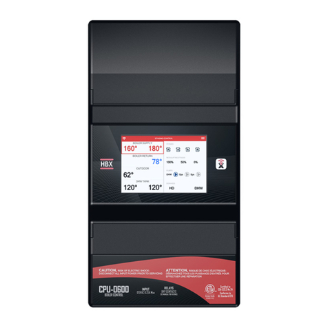
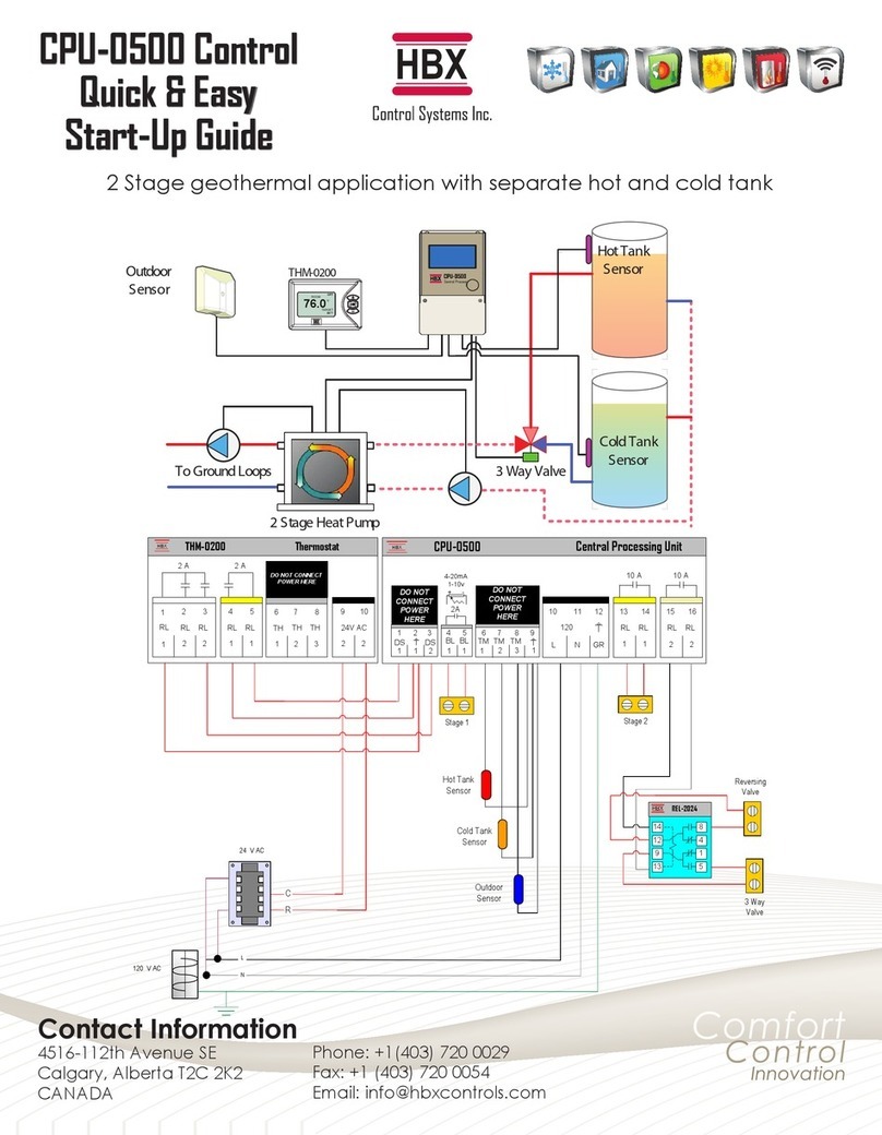
HBX Snowmelt Controller 1000 User manual

HBX Control Systems Inc.
Installation Manual
Snowmelt Controller 1000
Snowmelt Module 0100
Version 1.08

Control Systems Inc.
Comfort
Control
Innovation
HBX Snowmelt System
Version 1.08
Page 2
Table of Contents
TABLE OF CONTENTS
Getting Started ................................................................................................ 2
Safety Symbols ................................................................................................. 2
Receiving, Unpacking, Inspection and Storage .......................................... 2
Inspection ......................................................................................................... 2
Storage ............................................................................................................. 2
SNO-1000 General Technical Data ............................................................... 3
SNO-0100 General Technical Data ............................................................... 4
Installing the Module ....................................................................................... 4
Main Parts and Labels ..................................................................................... 5-6
Installation & Wiring ......................................................................................... 7-9
SNO-1000 Ports and Wiring ............................................................................. 8
SNO-0100 Ports and Wiring ............................................................................. 9
Dipswitch .......................................................................................................... 9
Display Features ............................................................................................... 10
Navigating the Control ................................................................................... 11
Program Lock Feature .................................................................................... 11
Programming ................................................................................................... 12-29
Status Screens .................................................................................................. 12
Programming Screens ..................................................................................... 12-29
Electrical & Mechanical Drawings ................................................................ 30-35
Troubleshooting & Fault Codes ...................................................................... 36
Typical design outside temperatures in North America .............................. 37
Warranty Information ...................................................................................... 38

HBX Snowmelt System
Version 1.08
Page 3
Control Systems Inc.
Comfort
Control
Innovation
HBX Snowmelt System
Version 1.08
RECEIVING, UNPACKING,
INSPECTION AND STORAGE
The SNO-1000 and SNO-0100 have gone through
rigorous quality control tests at the factory before
shipment. After receipt and before installation perform
the following checks:
Inspection
After unpacking the unit make sure the boxes contain:
SNO-1000 Package:
• SNO-1000 Snowmelt Control
• 1 Terminal Screwdriver (3.0mm)
• 3 Cable Ties
• 1 Remote Outdoor Temperature Sensor
• 3 Universal Temperature Sensors
SNO-0100 Package:
• SNO-0100 Snowmelt Module
• 1 Terminal Screwdriver (2.5mm)
• 32 Pin Connector
• 1 Slab Sensor
Make sure the part number on each unit corresponds
to the part numbers on the original box.
Storage
The SNO-1000 and SNO-0100 should be kept in their
original shipping cartons prior to installation. In order
to retain the warranty coverage they should be stored
properly:
• Store in a clean dry place
• Store within an ambient temperature range of
+10ºC to +40ºC
• If possible, store in an air-conditioned environment
where the relative humidity is less than 95%
• Do not store in places where the unit may come
into contact with corrosive gases or liquids
• Do not store in an area or upon an unstable
surface where it may become damaged due to
falling
GETTING STARTED
This manual will help with the installation, parameter
setting, troubleshooting and general maintenance
requirements for the control, and the module. To
guarantee the safe and reliable operation of your
snowmelt system, you must rst read this manual
in detail and take particular note of any and all
warnings or caution directives prior to connecting
to AC power.
Only suitably qualied individuals with
formal training in electrical and HVAC
controls should attempt the installation
of this equipment. Incorrect wiring and
installation will affect the warranty provided
with this unit. Wiring must be completed in
accordance with the codes and practices
applicable to the jurisdiction for the actual
installation.
The HBX SNO-1000 is a microprocessor
based control and as such is not to be
regarded as a safety (limit) control.
Please consult and install the heating or
cooling appliance in accordance with the
manufacturer’s recommendations.
SAFETY SYMBOLS
Extreme Hazard
This action poses a serious threat that
could result in personal injury or death,
as well as permanent damage to the
equipment. Proceed with caution.
Moderate Hazard
This action may cause personal injury or
have adverse effects on the installation
process if handled incorrectly.
Disconnect Power Source
The presence of low voltage(24VAC)
or high voltage(120VAC) could result in
personal injury or permanent damage to
components or equipment.
Point of Interest
Thispointclariespertinentinformation,
or brings your attention to an action
that may have adverse effects on the
installation process.

HBX Snowmelt System
Version 1.08
Page 4 © HBX Control Systems Inc. 2014
Nameplate Information:
The exterior label contains specic information
uniquetoyourHBXSnowmeltControlandidenties
some of the basic features. The label displays the
serial number which will match the serial number
on your actual Control, the lot number, the bar
code and the product’s ETL number.
Pulse Modulating Injection Theory:
For information about the controls PMIp/
PMIv capabilities see the technical bulletins
section of the HBX Control Systems Website:
www.hbxcontrols.com
GENERAL TECHNICAL DATA (SNO-1000)
Input Voltage:
120 VAC, ± 10%, 60Hz
3 x Optically Isolated Inputs:
20 - 240 VAC
3 x Thermistor Inputs:
Boiler/System Sensor/Outdoor
3 x Pump Output Relays:
240VAC 10A
2 x Auxiliary Output Relays:
240VAC 10A
Standard Communications:
RS-232
Real Time Clock Battery:
Lithium-Ion
Microprocessor:
16Bit, 20MHz
Languages:
English
Graphic Display:
128 x 64 pixels (55mm x 28mm viewable area)
Weight:
0.95 KG (2.1 lbs)
Dimensions:
190mm W x 168.2mm H x 72mm D
ETL Listings:
Meets CSA C22.2 No. 24
Meets UL Standard 873
ETL Control No. 3068143
Storage:
+10ºC to +40ºC
All I/O (inputs and outputs) are both colour
coded and keyed indexed for non-
interchangeability
Side View Side ViewFront View Rear View
72mm
70mm20 75mm 75mm
190mm 190mm
172mm9
63.2
168.2
63.2
Top ViewBottom View
SNO-1000
Snowmelt Control
SNO-1000
Snowmelt Control
Made In
Canada
Lot Number: 0000001
Serial Number: 0004-1204
Date: 12/21/08
3068143
V1.00V1.00V1.00

HBX Snowmelt System
Version 1.08
Page 5
Nameplate Information:
The exterior label contains specic information
uniquetoyourHBXSnowmeltModuleandidenties
some of the basic features. The label displays the
serial number which will match the serial number
on your actual module, the lot number, the bar
code and the product’s ETL number.
SNO-0100
Snowmelt Module
SNO-0100
Snowmelt Module
Made In
Canada
Lot Number: 0000001
Serial Number: 0004-1204
Date: 12/21/08
3068143
Installing the Module
PlacetheSNO-1000anddesiredSNO-0100onaat
surface. Align the 32-Pin connector with the holes
on the module and gently push into place. Next
slide the SNO-1000 onto the 32-Pin connection by
carefully matching up the holes and pins. When
installed correctly there is virtually no gap between
the units. With power applied to the assembly,
the rst (green) LED should be illuminated on the
module. This lit, green LED serves as conrmation
of both electrical and communications continuity.
GENERAL TECHNICAL DATA (SNO-0100)
2 x Thermistor Input
(10K Ohm)
1 x Snow Sensor Input
2 x Aux. Output Relays
(240VAC 10Amps)
Weight:
0.408Kg
Dimensions:
100mm W x 168mm H x 70mm D
ETL Listings:
Meets CSA C22.2 No. 24
Meets UL Standard 873
ETL Control No. 3068143
Storage:
10ºC to 40ºC
70mm 66mm17
Side View Front View Rear View Top View
168mm
100mm
63.2mm
86mm
Bottom View
SNO-0100
Snowmelt Module
SNO-0100

HBX Snowmelt System
Version 1.08
Page 6 © HBX Control Systems Inc. 2014
3. Menu and Programming Buttons:
These buttons will be used to set up the Control
during commissioning and for toggling between
displays or troubleshooting at a later date if
necessary.
4. Serial Number and Bar Code:
This label will identify the entire factory ordered
options and the date of manufacture. It can also
be used for re-ordering and will be required in the
event of factory service assistance or warranty
claim.
5. Communication Connection:
The standard communications port (RS-232) is
found directly below the bar code label. Optional
communications software needs to be purchased
to enable a connection. Please consult factory or
dealer.
Only a CAB-0100 can be inserted into this
connection without causing damage.
Example:
Viewing from top left and moving right in a
clockwise direction:
1. Back-Lit Graphic Display:
The display is one of the key features of the
Control. Depending upon which mode of
operation is selected, you will be able to view
most common system values simultaneously. It
will also serve as a visual indicator when in the
programming mode.
2. Lockable Keypad Option:
Once your system has been programmed and
optimized there should be little or no reason for
further changes. The Control has been designed
with the ability to physically “hard-lock” the
keypad to prevent tampering with the settings.
Refer to pg 11 for “hard lock” instructions.
2. Lockable
Keypad Cover
3. Menu / Reset /
Programming
Buttons
4. Serial Number /
Bar Code Tracking
5. Communication
Connection
6. 120 VAC
Pump Outputs
7. 120 VAC
Power Inputs
8. Boiler
Relays
9. Thermistor /
Sensor Inputs
10. Demand
Inputs
11. Backup
Battery
1. Graphic
Display

HBX Snowmelt System
Version 1.08
Page 7
to trigger a variety of commands within the
Control.
11. Backup Battery:
The lithium-ion battery is purely a back-up supply
for the real time clock and will keep the clock
refreshed during a power interruption to the
Control.
Prior to installation, please remove the
protective paper strip to activate the
back-up battery as shown below.
6. 120 VAC Pump Outputs:
There are three separate (3-wire) 120VAC output
power terminals designed to run either a pump or
fan.
7. 120 VAC Power Input:
There is one (3-wire) terminal block for incoming
120VAC power.
8. Boiler Relays:
These are used to run boilers. The SNO-1000 can
run up to 2 On/Off Boilers by itself.
9. Thermistor/Sensor Inputs:
There are three (2-wire) sensor/thermistor inputs.
Under no circumstance should power be
applied to these terminals! Permanent
damage to the Control’s circuitry may
result.
10. Demand Inputs:
There are three (2-wire) “demand” control inputs.
Control signals between 20-240VAC are designed
1. 32 Pin Connector Port
The 32-Pin Connector Port allows a 32 pin
connector to be used to connect the SNO-0100
to the SNO-1000 leaving virtually no gap between
the units.
2. Power and Communications LED
Withpowerappliedtotheassembly,therst(green)
LED should be illuminated on the module. This lit,
greenLEDservesasconrmationofbothelectrical
and communications continuity.
3. 120VAC Power Port
4. Relay Port
5. Modulating Output Boiler / Modulating
Valve or Pump
6. Thermistor Inputs
7. Snowmelt Sensor Port
D1
J2
SNOW
SENSOR
1 2 3 4
THERM(S)
5 6 7
MOD
8 9
1 2
RELAY
13 14 15
POWER
10 11 12
Snowmelt Module
2. Power and
Communications
LED
3. 120VAC Power Port
4. Relay Port
5. Modulating Output
Boiler / Modulating
Valve or Pump
7. Snowmelt
Sensor Port
6. Thermistor
Inputs
1. 32 Pin Connector Port

HBX Snowmelt System
Version 1.08
Page 8 © HBX Control Systems Inc. 2014
INSTALLATION & WIRING
The SNO-1000 and SNO-0100 are designed to be wall mounted, DIN rail mounted, or installed inside a separate
electrical enclosure. The unit should be mounted inside and be protected from falling water and high humidity
conditions. With all the covers in place it is designed to protect any individual from accidental electrical shock.
The Control has a built in 5Amp fast acting fuse to protect the circuitry on the Printed Circuit Board (PCB). The
unit is designed to power up to 3 pumps and 2 auxiliary relays of 10Amps each. As such, an upstream customer
supplied fuse or circuit breaker rated at a maximum of 30 amps must be in circuit. It is the installers responsibility
to provide either a 3 pin (3ft max) grounded plug and cable, or the unit must be wired directly to a breaker and
terminated inside the control box (terminals 17, 18 & 19).
All power wiring must be with a minimum of 18AWG wire.
Low power wiring ----------- insulated 18AWG (min.) wire to a max of 500ft.
Thermistor wiring ------------ insulated 18AWG (min.) wire to a max of 500ft.
It is recommended to use 18AWG Single Stranded Wire. It is also recommended to run signal and
power wiring in separate conduit.
Only suitably qualied individuals with formal training in electrical and HVAC controls should attempt
the installation of this equipment. Incorrect wiring and installation will affect the warranty provided with
this unit. Wiring must be completed in accordance with the codes and practices applicable to the
jurisdiction for the actual installation.

HBX Snowmelt System
Version 1.08
Page 9
P2 Relay - Any pump (or fan) output rated to
a max of 10Amps 120VAC. This relay is pre-
programmed to be the default (low temp) system
pump. When programmed for a mixing system.
P1 Relay - Any pump (or fan) output rated to
a max of 10Amps 120VAC. This relay is pre-
programmed to be the default boiler or (High
Temp) system pump.
Supply Power - The 3-wire 120VAC input to the
control. Protected by a 30Amp breaker or fuse.
Relay 2 - This relay is the default relay for bringing
on the 2nd Boiler or Boiler stage. It can be used as
an injection valve.
Relay 1 - This relay is the default relay for bringing
on the 1st Boiler or Boiler stage.
Misc Relays 1&2 are Dry Contacts and
rated for a max of 10Amps
Snowmelt Demand - This demand is used for the
main Snowmelt demand. This will put the control in
idle mode when no snow is present.
Forced Melt Demand - This demand will force the
control into melt mode. It will only stay in melt
mode for a predetermined amount of time. To use
again the user must take the demand away and
then reapply.
Zone Demand - This demand is used to tell the
control to only watch the extra slab zone. When
engaged the control will run the zone slab like a
setpoint.
Thermistor 1 - Boiler Sensor
Thermistor 2 - System Sensor
Thermistor 3 - Outdoor Sensor
TM1, TM2 & TM3 are designed for 10K Ohm
Thermistors and must never be subjected
to any external power supply (voltage or
current)
P3 Relay - Any pump (or fan) output rated to
a max of 10Amps 120VAC. This relay is pre-
programmed to be the default injection pump
relay when PMIp is the injection mixing strategy.
21
SD
1
SD
1
43
SD
2
SD
2
65
SD
3
SD
3RG
021
82
N
L
7262
RG
021
52
N
L
4232
RG
021
22
N
L
1202
RG
021
91
N
L
8171
LR
2
LR
6151
2
LR
1
LR
4131
1
MT
3
MT
2111
3
MT
2
MT
019
2
MT
1
MT
87
1
v042-02 v042-02 v042-02
EREHREWOPTCENNOCTONOD
A01 A01
A01 A01A01
0001SNO
XBH TINUGNISSECORPLARTNEC
Injection Pump
System Pump
Boiler Pump
Supply Power 120 VAC
Boiler 2
Boiler 1
Snow Melt Demand
Forced Melt Demand
Zone Demand
Boiler
System
Outdoor
Terminal Designations for SNO-1000
White Green Black RedBrown Blue Yellow Natural Black Red Blue Orange
DEMAND DEMAND DEMAND THERM THERM THERM RELAY RELAY PUMPPUMPPUMP
INPUT
POWER
1
13579111315246810 12 14 16 26232017 27242118 28252219
1122212333

HBX Snowmelt System
Version 1.08
Page 10 © HBX Control Systems Inc. 2014
Snowmelt Sensor - This is where you attach the
Snowmelt Sensor.
Take care not to mix up the wiring.
Thermistors - These are the inputs for the return
sensor and the second (only) slab zone sensor.
Modulating Output - This modulating output can
be used for a modulating boiler, modulating
valve, or it can run a VFD for a pump. This is a
4-20mA or 1-10v Signal.
Supply Power 120VAC - The 3-wire 120VAC input
to the control. Protected by a 30Amp breaker or
fuse.
Relay Outputs
These relay outputs are only used for a oating
action (power open / power close) valve or this is
the output for the slab (only) zone pump/valve.
Dipswitch
The SNO-0100 is able to output either a 4-20mA
signal or a 1-10VDC signal from contacts 8 and 9
using a modulating output.
For 4-20mA the dipswitch is set to OFF (up
position).
For 1-10VDC the dipswitch is set to ON (down
position).
SNOWMELT MODULE
SNO-0100
HBX
GR
120
12
N
L
1110
1C
SG
32
14
32
PWTM BL
1
BL
98
2
4-
20mA
1-10v
+ -
2
15
C
1
1413
TM
1
6
TM
2
75
C
DO NOT
CONNECT
POWER
HERE
Snowmelt Sensor
Thermistor Input
Modulating Output
Relay Outputs
Supply Power 120 VAC
Black Orange
INPUT
POWER
10 11 12567 89
SNOWMELT
SENSORTHERM(S) MOD
12
3
4
RELAY
13 14 15
12
NaturalNaturalNatural
green
red
white
black
shield
Normally Open
Common
Normally Open
onon
on
SNO-0100 Rear View
Dipswitch

HBX Snowmelt System
Version 1.08
Page 11
PROGRAMMING
DISPLAY FEATURES
The HBX display is a 128 x 64 pixel, back-lit graphic display on a blue background. In addition to displaying text
and icons it has the ability to provide you with visual graphing capabilities. These graphing capabilities will allow
you to get representative data and trending information of up to 2 independent feedback values.
Standard Screen
Alternate Screen
System Status
Tue
Jan 4 2011 12:00:45
Boiler
System
Outdoor
Return
SnowRate
162
54
12
72
42
Target
170
60
Output
%
IDL MLT ZN CWSD
FMD
Setpoint Zone ON
Forced Melt Demand ON
Idle ON
Warm Weather Shut Down
ON
Target
Temperature
Shown in
Column below
Real Time and Date Shown
Temperature Feedback
( deg. Fahrenheit shown)
WWSD
Snow Melt Demand ON
Cold Weather Shut Down
ON
ºF
ºF
ºF
ºF
System Status
S
Tue
Jan 4 2011 12:00:45
Slab
Zone
162
143
º
F
ºF
IDL Target
Temperature
Shown in
Column below
Idle ON
Setbacks

HBX Snowmelt System
Version 1.08
Page 12 © HBX Control Systems Inc. 2014
NAVIGATING THE CONTROL
The four large red buttons labeled “A”,
“B”, “C”, and “D” are used to make
your way through the programming
options within the Control.
Pressing the “A” or “B” button while
viewing the initial “System Status” and
“System Function” main screens will
toggle from screen to screen. Pressing
the “D” button will take you to the
“Programming Options” screen.
Pressing the “D” button again will
revert to the main system screens.
Once in the “Programming Options”
menu you may move the selection
indicator up and down by pressing
the “A” and “B” buttons, pressing the
“C” button will enter the selected option. Pressing the “C” button on options with limited choices (ie. on/off, yes/
no) will toggle the selection.
Pressing the “A” and “B” buttons on options with variable numerical choices (ie. temperature values, time settings)
will increase and decrease the selected amount. Pressing the “C” button upon completion will forward you to
the next step.
The “D” button can be used to revert to the previous menu.
AA B
B C
C D
D
Input: 120VAC 60Hz 5A
Relays: 240VAC 10A
Demand Signal: 20 - 240V
Model: CPU - 1000
CAUTION,
RISK OF ELECTRICAL SHOCK - DISCONNECT POWER PRIOR TO SERVICING
Certified to CSA C22.2 No 24
Conforms to UL Standard 873
Central Processing Unit
SNO-1000
PROGRAM LOCK FEATURE
To minimize the potential for unauthorized tampering of your control after commissioning, you have the ability to
limit/lock the programming menus.
TolocktheControl,usetwongerstopressandholddowntheAandBbuttonssimultaneouslyforapproximately
10 secs.
TounlocktheControl,usetwongerstopressandholddowntheCandDbuttonssimultaneouslyforapproximately
10 secs.
If the display ashes erratically, remove your ngers from the buttons and try again by pressing both buttons at
the same time.
AAB
BC
CD
D
Input: 120VAC 60Hz 5A
Relays: 240VAC 10A
Demand Signal: 20 - 240V
Model: CPU - 1000
CAUTION,
RISK OF ELECTRICAL SHOCK - DISCONNECT POWER PRIOR TO SERVICING
Certified to CSA C22.2 No 24
Conforms to UL Standard 873
Central Processing Unit
1000
AAB
BC
CD
D
Input: 120VAC 60Hz 5A
Relays: 240VAC 10A
Demand Signal: 20 - 240V
Model: CPU - 1000
CAUTION,
RISK OF ELECTRICAL SHOCK - DISCONNECT POWER PRIOR TO SERVICING
Certified to CSA C22.2 No 24
Conforms to UL Standard 873
Central Processing Unit
1000
Lock Feature Unlock Feature

Page 13
1 Startup Screen
This screen will be visible for approximately 5 seconds after plugging in the
control.
2 System Status Default
This is the main screen visible during normal operation of the Control. Settings
visible on this screen depend on the terminals currently active.
3 System Function
You can toggle between main screens by pressing either the A or B button.
For this control (with a single boiler selected) the screen will look like the one
pictured left (depending on current terminal activity).
4 System Status
This screen will display the slab and zone 2 status.
5 Programming - Control Options
To access the Programming Menu, press the D button. To scroll to one of the 5
options, press the A button to move down the page or the B button to move
up the page.
6 Programming - Control Options Enter
OncethedesiredselectionisashingyoumayselectitbypressingtheC
button.ToggletheashingselectionbypressingtheAorBbuttons.
11
Control Systems
SnowMelt
Control
Ver 1.00
System Status
Boiler Open °F
°F
°F
°F
Open
Open
Open
0
TARGET
90
4
OUTPUT
0%
SUN JAN 02 2011 00:13:53
System
Outdoor
Return
SnowRate
22
System Function
Boiler Pump OFF
OFF
OFF
OFF
CYCLES
21
21
0
0
System Pump
Injection
Boiler
33
System Status
Slab
Zone 2
Open °F
°FOpen
TARGET
35
1
44
Programming
1) Control Options
2)
SnowMelt Options
3)
Change Designs
4)
Zone 2 Options
5)
Graphing
55
Programming
2)
SnowMelt Options
3)
Change Designs
4)
Zone 2 Options
5)
Graphing
66
1) Control Options
STATUS SCREENS
PROGRAMMING SCREENS

Page 14 © HBX Control Systems Inc. 2014
7 Control Options Selections
1) Set up the display and clock
2) Program a permanent snow demand
3) Program a permanent zone demand
4) View temp values effecting each thermistor
5) Manually test each relay
6) View the running times of each boiler stage for all connected boilers
9 Display Options - Change Time
It is recommended that you setup the correct time on your Control before
conguringotheroptions,asthereal-timesettingsareeffectedbythe
“Change Time” feature.
8 Display Options
1) Set your date and time (MFG suggests to enter your clock setup now)
2) Reset the internal relay counter for pump and boiler cycles
3) Program and Display either ºF or ºC
4) Program the Control to allow for Daylight Savings time shifting
5) Phone and website information
6) Clears stage accumulated hours counter
Control Options
2)
Snow Always HD? N
3)
Zone Always HD? Y
4)
Mins and Maxes
5)
Testing
6) Stage Run Times
77
1) Display Options
Display Options
2) Reset Cycles
3) Display in °F
4) Dllite savings? N
5) Contact HBX
6) Reset Run Times
99
1) Change Time
Display Options
1) Change Time
2)
Reset Cycles
3)
Display in
º
F
4) D-lite Savings? N
5) CONTACT HBX
6) Reset Run Times
88
9C Display Options - Change Time - Day
Use the programming buttons to set the current day of the month on this
screen.
9B Display Options - Change Time - Month
Use the programming buttons to set the current month on this screen.
9A Display Options - Change Time - Year
Use the programming buttons to set the current year on this screen.
Day 00
9C9C
Month 00
9B9B
Year 2000
9A9A

Page 15
12 Display Options - D-Lite Savings
Pressing the “C” button with the “D-Lite Savings” option selected will allow you
to program the Control to allow for Daylight Savings time shifting.
11 Display Options - Display in °F/°C
Pressing the “C” button with the “Display in °F/°C” option selected will allow
you to program the Control and display in either ºF or ºC.
10 Display Options - Reset Cycles
Pressing the “C” button with the “Reset Cycles” option selected will reset the
internal relay counter for the systems devices. Those devices are visible on the
“System Function” screen.
Display Options
3) Display in °C
4) D-lite savings? Y
5) Contact HBX
6) Reset Run Times
1212
1) Change Time
2) Reset Cycles
Display Options
3) Display in °C
4) D-lite savings? N
5) Contact HBX
6) Reset Run Times
1111
1) Change Time
2) Reset Cycles
Display Options
3) Display in °F
4) D-lite savings? N
5) Contact HBX
6) Reset Run Times
1010
1) Change Time
2) Reset Cycles
9D Display Options - Change Time - Weekday
Use the programming buttons to set the corresponding day of the week on this
screen (Sunday = 1).
9F Display Options - Change Time - Minute
Use the programming buttons to set the current minute on this screen.
9E Display Options - Change Time - Hour
Use the programming buttons to set the hour on this screen.
Weekday 1
(Sunday = 1)
9D9D
Min 00
9F9F
Hour 00
9E9E

Page 16 © HBX Control Systems Inc. 2014
13 Contact HBX Controls
By selecting #5 on the Programming screen the manufacturers contact
information can be viewed.
15 Permanent Snow Heat Demand
This setting is used when you would like a permanent demand on your snow
zone. If snow always heat demand is set to ‘Y’ then the snow zone will be in idle
mode until snow is seen by the snow sensor and it exceeds the desired settings.
The control will shut down the snow zone on a WWSD or CWSD.
(Y or N) Default: N
18 Thermistor 1
Each min/max value also has a time and date stamp to show when the value
was reached.
This can serve as a valuable troubleshooting tool while diagnosing
system problems.
14 Display Options - Reset Run Times
Pressing the “C” button with the “Reset Run Times” option selected will clear
the stage accumulated hours counter. To view the stage runtime, select the
“Stage
Run Times” option within the “Control Options” menu.
17 Mins and Maxs
Allows you to look at up to six different thermistor min/max temperature
extremes and reset back to zero. When formatting the Control, existing min/
max values are reset. Selecting the ‘Reset All’ option clears the time and date
stamps.To see updated Min/Max values return to the System Status screen to
refresh the view.
16 Permanent Zone Heat Demand
This setting is used when you would like to have a permanent demand on
the setpoint zone. If zone always heat demand is set to ‘Y’ then the setpoint
zonewillalwaystrytokeepthatzonesatisedbasedonthedesiredsetpoint
temperature.
(Y or N) Default: N
HBX Control Systems
Calgary, AB, Canada
1-403-720-0029
www.hbxcontrols.com
Press B to Continue
1313
Control Options
2) Snow Always HD? N
3)
Zone Always HD? Y
4)
Mins and Maxes
5)
Testing
6) Stage Run Times
1515
1) Display Options
Thermistor 1
30/09/05
03HRS
24/09/05
16HRS
Min Temp
89
º
F
Max Temp
201
º
F
1818
Display Options
3) Display in °C
4) D-lite savings? Y
5) Contact HBX
6) Reset Run Times
1414
1) Change Time
2) Reset Cycles
Mins and Maxs
1)
Thermistor 1
2)
Thermistor 2
3)
Thermistor 3
4)
Thermistor 4
5)
Thermistor 5
6)
Thermistor 6
7) Reset All
1717
Control Options
2) Snow Always HD? N
3) Zone Always HD? N
4)
Mins and Maxes
5)
Testing
6) Stage Run Times
1616
1) Display Options

Page 17
19 Control Options - Testing
This allows you to manually test/run each relay for up to 30 seconds.
You can cycle the relay faster by pressing the C button, this skips the
30 second elapse time.
21 Control Options - Stage Run Times
This allows you to view cumulative running times for your boiler stages. This is
reset in the Display Options menu.
24 SnowMelt Options - Boiler Options
Selection #1 will direct you to the System Options screen.
20 Control Options - Testing Relays
Thereareverelaysonthemaincontrolbox.Relayssixandhigherwillberun
with the corresponding Expansion Module connected. By continually pressing
the ‘A’ button you can access extra screens showing Relays #8 and
higher.
Test relay 16 and 17 for oating up and down, test relay 17 for Zone 2.
23 SnowMelt Options
The Snowmelt options menu provides settings for your Snowmelt installation.
22 Control Options - Stage Run Times
Whenoperatingaboiler,youcandeterminetheringsequenceandruntimes
of each boiler/stage from this screen.
Control Options
1)
Display Options
2)
Always HD? N
3) Use Room Therm? N
4)
Mins and Maxs
5)
Testing
6) Stage Run Times
1919
Control Options
1)
Display Options
2)
Always HD? N
3) Use Room Therm? N
4) Mins and Maxs
5) Testing
6) Stage Run Times
2121
Snow Melt Options
2) Snow Melt Settings
3)
Demand Melt Time
4)
No Priority
5) Priority Time
6) Injection is PMIv
2424
1) Boiler Options
Testing
1)
Relay # 1
2)
Relay # 2
3)
Relay # 3
4)
Relay # 4
5)
Relay # 5
6)
Relay # 6
7) Relay # 7
2020
Programming
2) SnowMelt Options
3)
Change Designs
4)
Zone 2 Options
5)
Graphing
2323
1) Control Options
2222 Stage Run Times
1) 67:48
2) 12:34
3) 01:03
4) 00:00

Page 18 © HBX Control Systems Inc. 2014
25 System Options
Thesestepsprovidethenecessaryoptionstoconguretheboilerstaging
component in your system.
System Options
2) Pump Options
3)
# of Stages 1
4)
Rotate Boilers? Y
5) Mod Boiler Options
6) Mod PrePurge ON? N
7) Use Flow Proof? N
2525
1) Staging Options
26 Staging Options - Hi/Lo Fire
Enable the Hi/Lo Fire option if you are utilizing dual stage boilers with high and
low output settings.
At least two stages must be selected for Hi/Lo Fire to be programmed
to Y.
28 Staging Options - Fixed Last
FixedLastdesignatesaboilertofunctionasthelastringboiler,regardlessof
settingsuchasrotateboiler.Thisboilerwillconsistentlybethelasttorewhena
heat demand is present.
Hi/Lo Fire option must be selected to Y in order for this option to be
enabled.
27 Staging Options - Fixed First
FixedFirstdesignatesaboilertofunctionastheinitialringboiler,regardlessof
settingssuchasrotateboiler.Thisboilerwillconsistentlybethersttorewhen
a heat demand is present.
29 Staging Options - Lo/Lo - Hi/Hi
The Lo/Lo - Hi/Hi function of the Control instructs a heating system containing
twodualstageboilerstoengagetherststageofeachboilerpriortoigniting
the second stage of either boiler. The Control will turn on the second stages of
the boilers as the call for heat is required.
Staging Options
1) Hi/Lo Fire? N
2) Fixed First? N
3) Fixed Last? N
6) Min Boiler LagTime
4) Lo/Lo - Hi/Hi? N
2626
5) Boiler Diff’ntial
Staging Options
1) Hi/Lo Fire? N
2) Fixed First? N
3) Fixed Last? N
6) Min Boiler LagTime
4) Lo/Lo - Hi/Hi? N
2828
5) Boiler Diff’ntial
Staging Options
1) Hi/Lo Fire? N
2) Fixed First? N
3) Fixed Last? N
6) Min Boiler LagTime
4) Lo/Lo - Hi/Hi? N
2727
5) Boiler Diff’ntial
30 Staging Options - Boiler Differential
The Boiler Differential option creates the margin for error above or below
the target temperature. A higher boiler differential will allow for a greater
discrepancy in target/actual temperature before there is a heat demand.
The boiler differential can only be manually set for single boiler
applications.
Staging Options
1)
Hi/Lo Fire? N
2)
Fixed First? N
3) Fixed Last? N
6) Min Boiler LagTime
4) Lo/Lo - Hi/Hi? N
3030
5) Boiler Diff’ntial
Staging Options
1) Hi/Lo Fire? N
2) Fixed First? N
3) Fixed Last? N
6) Min Boiler LagTime
4) Lo/Lo - Hi/Hi? N
2929
5) Boiler Diff’ntial

Page 19
31 Staging Options - Boiler Differential
This option allows the user to set the differential for a single boiler only. This will
override automatic differential and PID control for the boiler.
Boiler Diff’ntial
NB. Single Stage Only
AUTO
3131
32 Staging Options - Minimum Boiler Lag Time
The Minimum Boiler Lagtime enforces a minimum time period that must expire
before a new boiler cycle may begin. This minimizes short cycling and functions
topromoteamoreenergyefcientsystem.
33 Staging Options - Minimum Boiler Lag Time Cont’d
This screen allows you to set the desired time frame that must pass before
consecutive boiler cycles may commence.
(3 - 200mins) Default: 3 Minutes
Staging Options
1)
Hi/Lo Fire? N
2)
Fixed First? N
3) Fixed Last? N
6) Min Boiler LagTime
4) Lo/Lo - Hi/Hi? N
3232
5) Boiler Diff’ntial
Boiler Min LagTime
3 mins
3333
34 Pump Options
Access Pump Options to setup and differentiate between boiler pumps and
system pumps with post purge features, etc.
35 Pump Options - 1 Pump/Boiler
This feature asks you whether or not the boiler pumps are controlled by the
boiler circuit.
N = Boiler pumps controlled by boiler circuit
Y = Boiler pumps controlled by SNO-1000
When selected ‘Y’ an automatic 30 sec post purge time is activated for the
boiler pumps (Set on Option 3).
36 Pump Options - Constant System Pump
Selection #2 gives you the option to run the system pump continuously
regardless of a call for heat.
System Options
2) Pump Options
3)
# of Stages 1
4)
Rotate Boilers? Y
5) Mod Boiler Options
6) Mod PrePurge ON? N
7) Use Flow Proof? N
3434
1) Staging Options
Pump Options
2) Const Sys Pump? N
3) Post Purge 30 Sec
3535
1) 1 Pump/Boiler? N
Pump Options
2) Const System Pump? N
3) Post Purge 30 Sec
3636
1) 1 Pump/Boiler? N

Page 20 © HBX Control Systems Inc. 2014
37 Pump Options - Constant System Pump
Use caution when activating the constant system pump feature.
38 Pump Options - Post Purge
Selection #3 gives you the ability to program a post purge cycle time which
runs all pumps for a selectable duration (30-240 Secs) after the initial off-signal
has been sent. Post purge does not effect the injection pumps.
This feature applies to both boiler pumps and system pumps.
40 # of Stages
Access staging options for your heating source which sets the number of stages
in the system.
(0 - 10 stages) Default: 1 Stage
39 Pump Options - Post Purge Time
This screen allows you to set the desired time frame for system and boiler
pumpstorunafteraheatdemandhasbeensatised.Thisfeaturesprocessisto
circulate tempered water into the loop which would otherwise be trapped in
the boiler, causing energy waste.
(30 - 240secs) Default: 30 Seconds
41 # of Stages Cont’d
The number of stages available ranges from 0-10. For systems with 3 or more
stages expansion modules are required.
42 Rotate Boilers
Selection #4 gives you the ability to rotate the boiler sequence for lead/lag
and effectively accomplish equal run time per boiler. Rotation is executed
every 48 hours (running hours).
The factory default setting for rotate boilers is ‘Y’.
This setting will turn the
system pump on always.
Press B To Continue
CAUTION
3737
Pump Options
2) Const System Pump? N
3) Post Purge 30 Sec
3838
1) 1 Pump/Boiler? N
System Options
2) Pump Options
3) # of Stages 1
4)
Rotate Boilers? Y
5) Mod Boiler Options
6) Mod PrePurge ON? N
7) Use Flow Proof? N
4040
1) Staging Options
Post Purge Time
30 Secs
3939
Number of Stages
NB. HI/LO = 2 Stages
1
4141
System Options
2) Pump Options
3) # of Stages 1
4) Rotate Boilers? Y
5) Mod Boiler Options
6) Mod PrePurge ON? N
7) Use Flow Proof? N
4242
1) Staging Options
This manual suits for next models
2
Table of contents
Other HBX Control System manuals
Popular Control System manuals by other brands

HEIDENHAIN
HEIDENHAIN iTNC 530 HSCI Technical manual

Linear Access
Linear Access AM/II Installation and programming instructions

Ruida Technology
Ruida Technology LFS-PM Series operating manual

GSK
GSK GSK983Ma user manual

RF SOLUTIONS
RF SOLUTIONS MAINSSWITCH-8SL1 quick start guide

Lehigh
Lehigh DX3 Command reference

MGM
MGM BMO Series Use and maintenance

Belimo
Belimo VRP-M Product information

Bryant
Bryant ZONE PERFECT PLUS ZONEBB2KIT installation instructions

Delta Electronics
Delta Electronics UNOcentral user manual

Weir
Weir SPM SafeEdge ARC System Operation Instruction and Service Manual

ELCOS
ELCOS CIM-130-KLRV Instruction and user's manual