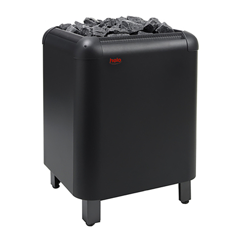
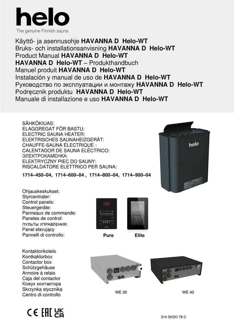
Helo VIENNA D Series User manual

SÄHKÖKIUAS:
ELAGGREGAT FÖR BASTU:
ELECTRIC SAUNA HEATER:
ELEKTRISCHES SAUNAHEIZGERÄT:
CHAUFFE-SAUNA ÉLECTRIQUE :
CALENTADOR DE SAUNA ELÉCTRICO:
ЭЛЕКТРОКАМЕНКА:
ELEKTRYCZNY PIEC DO SAUNY:
ELEKTRIKERIS:
RISCALDATORE ELETTRICO PER SAUNA:
ELEKTRICKÉ SAUNOVÉ TOPIDLO:
ELEKTROMOS SZAUNAKÁLYHA:
1714 – 450 – 04
1714 – 600 – 04
1714 – 800 – 04
1714 – 900 – 04
7014640 314 SKSM 212 C
Käyttö- ja asennusohje VIENNA D
Bruks- och installationsanvisning VIENNA D
Product Manual VIENNA D
VIENNA D – Produkthandbuch
Manuel produit VIENNA D
Instalación y manual de uso de VIENNA D
Руководство по эксплуатации имонтажу VIENNA D
Podręcznik produktu VIENNA D
Kasutusjuhend VIENNA D
Manuale di installazione e uso VIENNA D
Návod k instalaci a použití Vienna D
Telepítési és felhasználói kézikönyv Vienna D
REWARD YOURSELF

ELECTRIC SAUNA HEATER: 400V – 415V 3N~
1712 – 450 – 04
1712 – 600 – 04
1712 – 800 – 04
CONTROL PANELS and CONTACTOR BOXES:
1601 – 12 + 2005 – 3 (RA 12 + WE 3) Digi 2
1601 – 13 + 2005 – 3 (RA 13 + WE 3) Digi 1
1418 – 2 1517-3 (OT – 2 PS-3)
1418 – 2 1519 (OT – 2 PUi)
314 SKSO 212-3 A
GENUINE SAUNA & STEAM
Installation and User Manual Vienna D
REWARD YOURSELF

Contents Page.
1. Quick instructions for use of the sauna heater 3
1.1 Check before taking a sauna bath 3
1.2 Operation of the sauna heater controls 3
2. Information for users 3
2.1 Sauna room 3
2.2 Heating the sauna 3
2.3 Recommended sauna room ventilation 4
2.4 Installing the sensor near a supply air vent 4
2.5 Sauna heater stones 5
2.6 If the sauna heater will not heat up 6
2.7 Preparing for sauna heater installation 6
2.8 Installation 6
2.9 Heater safety distances and sensor position 7
2.10 Mains connection 8
2.11 Electric heating toggle 8
2.12 Location the connection box for connection cable in the sauna room 9
2.13 Wiring diagram 9
2.14 Door switch 10
2.15 Principle image when Digi 1601 – 12 is used as control panel 11
2.16 Principle image when OT-2… is used as control panel 12
2.17 Spare parts for Vienna D-electric sauna heater 13
3. WARRANTY POLICY 14
4. ROHS 15
Image and Table:
Image 1 Recommended sauna room ventilation 4
Image 2 Heaters installation 7
Image 3 Heater safety distances and sensor position to wall 7
Image 4 Sensor ceiling installation (OLET 19) 7
Image 5 Sensor ceiling installation (OLET 6-1) 7
Image 6 Location for the connection box 9
Image 7 Wiring diagram 9
Image 8 Installing the door switch 10
Image 9 Wiring diagram when Digi 1601 – 12 is used as control panel 11
Image 10 Wiring diagram when OT 2 PS-3 or OT-2-PUi is used as control panel 12
Image 11 Exploded view diagram of the heater 13
Table 1 Safety clearances 8
Table 2 Cable and Fuse 8
Table 3 Spare parts for Vienna D 13
Installation and User Manual Vienna D 2

1. Quick instructions for use of the sauna heater
1.1 Check before taking a sauna bath
1. The sauna room is suitable for taking a sauna bath.
2. The door and the window are closed.
3. The sauna heater is topped with stones that comply with the manufacturer's recommendations, the
heating elements are covered with stones, and the stones are piled sparsely.
NOTE! Ceramic rocks are not allowed.
A pleasant, smooth sauna bath temperature is about 70 °C degrees.
Rearrange the sauna stones at least once a year and replace any weathered stones. This enhances air circu-
lation between the stones, which extends the useful life of the heating elements.
If you encounter any problems, please contact the manufacturer's warranty service shop.
For additional information about enjoying a sauna bath, please visit our website at www.helo.fi
1.2 Operation of the sauna heater controls
The main switch is on the side of the contactor case. The type plate shows the position of the switch. ( 0 I )
For contactor case and control panel use, refer to the specific operating manuals.
2. Information for users
Persons with reduced physical and mental capacity, sensory handicap, or little experience and knowledge
about how the device is operated (e.g. children), should only operate the device while supervised or according
to instructions given by the persons in charge of their safety.
Make sure that children aren't playing with the sauna heater.
2.1 Sauna room
The walls and ceiling of a sauna room should be thermally well insulated. All surfaces that store heat, such as
tiled and plastered surfaces must be insulated. It is recommended to use wooden panel cladding inside the
sauna room. If there are heat storage elements in the sauna room, such as decorative stone, glass etc., note
that these elements may extend the pre-heating period even though the sauna room is otherwise well insu-
lated (see page 6, section 2.7. Preparing for sauna heater installation).
2.2 Heating the sauna
Before turning the sauna heater on, make sure the sauna room is suitable for taking a sauna bath. When
heated for the first time, the sauna heater may emit some odour. If you detect any odour while the sauna
heater warms up, disconnect the sauna heater briefly, and air the room. Then turn the sauna heater back on.
The sauna heater is turned on by twisting the timer knob, and the temperature is adjusted from the thermostat
knob.
You should turn the sauna heater on roughly an hour before you plan to take a sauna bath, so that the stones
have time to heat up properly and the air warms up evenly in the sauna room.
Do not put any objects on the sauna heater. Do not dry clothes on the sauna heater or anywhere in its
vicinity.
Installation and User Manual Vienna D 3

2.3 Recommended sauna room ventilation
Image 1 Recommended sauna room ventilation
1. Sauna room 3. Electric sauna heater 5. Exhaust flue or channel
2. Washroom 4. Exhaust valve 6. Door to the sauna room
7. A ventilation valve can be installed here to be kept closed while the sauna is heated and during bathing.
Inlet vent can be positioned in the A zone. Make sure the incoming fresh air will not interfere with (i.e. cool down)
the sauna heater's thermostat near the ceiling.
The B zone serves as the incoming air zone, if the sauna room isn't fitted with forced ventilation. In this case, the
exhaust valve is installed min 1m higher than the inlet valve.
DO NOT ISTALL INLET VALVE WITHIN ZONE C, IF THE SAUNA HEATER'S CONTROL THERMOSTAT IS LO-
CATED AT THE SAME ZONE.
2.4 Installing the sensor near a supply air vent
The sauna room air should be exchanged six times in an
hour. The diameter of the supply air pipe should be
between 50 and 100 mm.
A circular air supply vent (360°) must be
installed at least 1000 mm away from the sensor.
An air supply vent with a flow-directing panel
(180°) must be installed at least 500 mm away from
the sensor. Air flow must be directed away from the
sensor.
Installation and User Manual Vienna D 4
55
4
4
2
1
1
1
A
7
A
min
500 mm
6
3
B
3
B
C
C
C
C A
1000 mm
360° 1000 mm
180° 500 mm
Sensor
Sensor

2.5 Sauna heater stones
Quality stones meet the following requirements:
- Sauna stones should withstand heat and heat variation caused by vaporisation of the water thrown on the
stones.
- Stones should be rinsed before use in order to avoid odour and dust.
- Sauna stones should have an uneven surface to supply a larger surface for the water to evaporate from.
- Sauna stones should be large enough, measuring about 50–80 mm to allow good ventilation between the
stones. This extends the useful life of the heating elements.
- Sauna stones should be piled sparsely in order to enhance ventilation between the stones. Do not bend the
heating elements together or against the frame.
- Rearrange the stones regularly (at least once a year) and replace small and broken stones with new, larger
stones.
- Stones are piled so that they cover the heating elements. Do not, however, pile a large heap of stones on the
heating elements. For a sufficient amount of stones refer to Table 1 on page 8. Any small stones in the package
of stones must not be piled on the sauna heater.
- The warranty does not cover defects resulting from poor ventilation caused by small and tightly packed stones.
- Structural clay tiles are not allowed. They may cause damage to the sauna heater that will not be covered
by the warranty.
- Do not use soapstone as sauna rocks. Any damages resulting from this will not be covered by the stove
warranty.
- Do not use lava stone as sauna rocks. Any damages resulting from this will not be covered by the stove
warranty.
- DO NOT USE THE HEATER WITHOUT STONES.
Installation and User Manual Vienna D 5

2.6 If the sauna heater will not heat up
If the sauna heater will not heat up, please check that:
- the power is on;
- the main fuses of the sauna heater are intact;
- is there any error messages on the control panel. In case of an error message on the control
panel, please refer to the control panel instructions.
THE PERSON INSTALLING THE SAUNA HEATER SHOULD LEAVE THESE INSTRUCTIONS AT THE PREM-
ISES FOR THE FUTURE USER.
2.7 Preparing for sauna heater installation
Check the following before installing the sauna heater:
1. The ratio of the heater's input (kW) and the sauna room's volume (m3). Volume/input recommendations are
presented in Table 1 on page 8. The minimum and maximum volumes must not be exceeded.
2. The sauna room ceiling must be min 1900 mm high.
3. Uninsulated and masonry stone walls extend the preheating time. Each square metre of plastered ceiling or
wall surface adds 1.2 m3to the sauna room's volume.
4. Check page 8 Table 2 section for a suitable fuse size (A) and the correct diameter of the power supply
cable (mm²) for the sauna heater in question.
5. Conform to the specified safety clearance around the sauna heater.
There should be enough room around the sauna heater for maintenance purposes, a doorway etc.
2.8 Installation
Follow the safety clearance specifications on page 8. when installing the sauna heater. Thin panel is not a suitable
mounting base. The mounting base must be reinforced with timber behind the panel. The minimum clearances
specified on page 8 table 1 must be followed also in case the sauna room wall materials are incombustible.
Walls or ceilings must not be clad with fibre-reinforced plaster board or other light-weight cladding, because they
may cause a fire hazard.
A single sauna heater is allowed per a sauna room.
Installation and User Manual Havanna D 6
Installation and User Manual Havanna D 6
Installation and User Manual Vienna D 6

2.9 Heater safety distances and sensor position
Image 2 Heaters installation
Image 3 Heater safety distances and sensor position to wall
Image 4 Sensor ceiling installation (OLET 19) Image 5 Sensor ceiling installation (OLET 6-1)
Installation and User Manual Vienna D 7
OLET 19 OLET 6-1
Image 4. Alternative installation location
for the sensor when using the contactor
casing WE 3 and the Digi 1 or 2
control panel. Sensor OLET 19
Image 5. NOTE: Only ceiling installation when using the
control panels 1418-2-1517-3 (OT-2-PS-3) and
1418-2-1519 (OT-2-PUi).
The sensor must not be installed on the wall when using the
Havanna D Heater
150
267 B
J
Minimum distances for the
mounting (mm)
Screw 6 x 40 (2kpl)
Screw 6 x 16 (2kpl)
Drill. Ø3,5 mm
Absolute measure of 40mm
from ceiling
Absolute measure of 40mm
from ceiling
K
A 402 A
min 20
min 30
min 20
min 30
F
min 1900
270 D
OLET 19 (mm)
OLET 19

Table 1 Safety clearances
Power
kW
Power supply cable H07RN –F/ 60245 IEC 66
mm²
400V - 415V 3N~
Fuse
A
4,5 5 x 1,5 3 x 10
6,0 5 x 1,5 3 x 10
8,0 5 x 2,5 3 x 16
Table 2 Cable and Fuse
2.10 Mains connection
The sauna heater must be connected to the mains by a qualified electrician and in compliance with current regula-
tions. Sauna heater is connected with a semi-permanent connection. Use A07BB-F or H07RN-F (60245 IEC 66)
cables or a corresponding type. Other output cables (signal lamp, electric heating toggle) must also adhere to these
recommendations. Do not use PVC insulated cable as a connection cable for the sauna heater.
A multipolar (e.g. 7-pole) cable is allowed, if the voltage is the same. In the absence of a separate control current
fuse, the diameter of all cables must be the same, i.e. in accordance with the front fuse. For example, in an 8 kW
sauna heater the diameter of separate cables to the signal lamp and the mains control unit has to be at least 2.5
mm².
The connecting box on the sauna wall should be located within the minimum safety clearance specified for the
sauna heater. The maximum height for the connection box is 500 mm from the floor (Image 6 Location for the con-
nection box, page 9). If the connection box is located at 500 mm distance from the heater, the maximum height is
1000 mm from the floor.
Sauna heater insulation resistance: The sauna heater heating elements may absorb moisture from air, e.g. during
storage. This may cause bleeder currents. The moisture will be gone after a few heating sessions. Do not connect
the heater power supply through a ground fault interrupter.
Adhere to the effective electrical safety regulation when installing the sauna heater.
2.11 Electric heating toggle
Electric heating toggle applies to homes with an electric heating system.
Sauna heater has connections (marked 55) for controlling the electric heating toggle. Connectors
55 and the heating elements are simultaneously live (230V). The sauna heater thermostat also
controls the heating toggle. In other words, home heating turns on once the sauna thermostat cuts
power off the sauna heater.
Power Saunaroom Minimum distance to Stone
kW
Volume Height Side
wall
A
mm
In front
of
D
mm
Ceiling
F
mm
Floor
K
mm
B
mm
J
mm
min. max.
Circa Circa
kg kg
min.
m³ max.
m³
min. mm
4,5 3 6 1900 40 60 1200 110 114 390 12 20
6,0 5 9 1900 60 80 1200 110 134 390 12 20
8,0 8 12 1900 80 100 1200 110 164 390 20 20
Installation and User Manual Vienna D 8

Image 6 Location for the connection box
2.12 Location the connection box for connection cable in the sauna room
A = Specified minimum safety clearance
1. Recommended location for the connection box
2. Silumin box recommended in this area.
3. This area should be avoided. Always use a silumin box.
In other areas, use a heat-resisting box (T 125 °C) and heat-resisting cables (T 170 °C). The connection box
must be clear of obstacles. When installing the connection box to zones 2 or 3, refer to the instructions and
regulations of the local energy supplier.
2.13 Wiring diagram
Image 7 Wiring diagram
Installation and User Manual Vienna D 9
200 mm
A A
3.
2.
1.
500 mm
KIUAS
500 mm
Heater
2
1 2 3 4 5 6
Teho, Effekt
Input, Leistung
kW
Lämpövastukset, Värmeelement,
Heating elements, Heizeelement
4,5
6,0
8,0
230 V
SEPC 63 SEPC 64 SEPC 65
1500W 2000W 2670W
1,2,3 1,2,3
354 SKSM 152 A
1,2,3
N U V W
3
1

2.14 Door switch
The door switch refers to the switch on the sauna door. This switch complies with the regulations laid down in
Section 22.100 of the standard EN 60335 2-53. Public and private saunas, i.e. saunas where the heater can
be switched on from outside the sauna or by using a timer, must have a door switch.
The control panels in Helo contactor cases WE3 and Digi 1 and 2 can be fitted with either a Helo DSA 1601 –
35 (RA – 35) door switch adapter (item number 001017) or a Helo door switch adapter (item number
0043233). For more information, please refer to the use and installation instructions for the DSA device.
Image 8 Installing the door switch
Installation and User Manual Vienna D 10
Door switch
DSA
Magnet Max 18 mm
Connection boxMin 300mm
Sensor
WE 3
or
Heater
Digi

2.15 Principle image when Digi 1601 – 12 is used as control panel
4
3
2
1
4
3
2
1
A 1 2 3 4 5 B1 2 3 4 5
A 1 2 3 4 5 B1 2 3 4 5
Image 9 Wiring diagram when Digi 1601 – 12 is used as control panel
1 Blue
2 White
3 Red
4 Yellow
Limiter
Contactor box
Contactor box
Sensor cable
Control panel
1601-2812
Connector strip
A1 Valk Vit White Weiss
A2 Ruskea Brun Brown Braun
A3 Vihreä Grön Green Frün
A4 Kelt Gul Yellow Gelb
A5 Harm Grå Grey Grau
B1 Rosa Ljusröd Pink Rose
B2 Sin Blå Blue Blau
B3 Pun Röd Red Rot
B4 Musta Svart Black Schwarz
B5 Violetti Violett Violet Violett
Sensor
OLET 19
Silicone 4 x 0.25mm
2
Sauna heater
LiYY 10 x 0.25mm
2
Contactor box
WE 3
Control panel
1601-12
Power supply
400V – 415V 3N~
Installation and User Manual Vienna D 11

2.16 Principle image when OT-2… is used as control panel
4
3
2
1
4
3
2
1
Image 10 Wiring diagram when OT 2 PS-3 or OT-2-PUi is used as control panel
Installation and User Manual Vienna D 12
1 Blue
2 White
3 Red
4 Yellow
Limite
r
Contactor box Sensor cable
Connector strip
Sensor OLET 6-1
Silicone 4 x 0.25mm
2
Sauna heater
Power supply
400V – 415V 3N~
Control panel
OT-2-PS-3
OT-2-PUi
Control panel
OT
-
2PS
-
3orOT
-
2
-
PUi

2.17 Spare parts for Vienna D-electric sauna heater
Image 11 Exploded view diagram of the heater
Table 3 Spare parts for Vienna D
Parts Product number Product title Vienna
450 D Vienna
600 D Vienna
800 D
1 4071002 Vienna basic grate 1 1 1
2 7712000 Cable clamp NKWA 1 1 1 1
3 7812550 Mains connector NLWD 1-1 1 1 1
4 4316222 Heating element SEPC 63
230V 1500W 3 - -
4 4316221 Heating element SEPC 64
230V 2000W - 3 -
4 4316220 Heating element SEPC 65
230V 2670W - - 3
5 7513002 Philips screw
M5 x 10 3 3 3
Installation and User Manual Vienna D 13

3. WARRANTY POLICY
1. General
Products manufactured by Helo Ltd. (manufacturer) are covered by the warranty conditions provided here. The manufacturer
guarantees the quality and operation of their products for the duration of the warranty period.
For the warranty to be valid, the buyer must follow the manufacturer's instructions regarding the placement, installation, usage and
maintenance of the products, as well as instructions regarding the qualities of the heater stones.
This warranty applies to products sold and used within the EU.
2. Warranty for electric heaters, control panels and steam generators.
For family use the warranty is valid for 24 months from the date of purchase or from the date of receipt of the construction site where it
is installed, whichever is later. For any other use the corresponding warranty is 3 months. The warranty for institutional and communal
sauna heaters and their control devices is 12 months. The warranty for evaporators is 24 months, subject to adherence to the
conditions in section 2.3. The warranty period of five (5) years for Premium sauna heaters applies to family use in Finland and in
Sweden, in accordance with these warranty conditions.
The warranty for an electric sauna heater is subject to the following conditions:
2.1 The stones in the heater used in an apartment must be rearranged and any crumbled stones must be replaced at least once a year
during the warranty. The stones in the premium heaters must be replaced once a year during the warranty period. Evidence of the
exchange must be provided in case of ANY RECLAMATION.
2.2 The stones in the heater used for institutional/ professional use must be rearranged at least three times a year during the warranty
period. In addition, the heater stones must be replaced at least once a year. Evidence of the exchange must be provided in case of
ANY RECLAMATION.
2.3 If the heater has a steam generator, the steam generator must be emptied after every use. Water softening and limescale removal
must be carried out according to the instructions. This clause applies to all steam generators.
2.4 If the heater is integrated in to the sauna benches, the bench model must allow lifting of the lower bench and its frame without tools.
The warranty does not cover the dismantling and reassembly of sauna benches.
2.5 The warranty is valid only when products are used with Helo-control panels.
The sales receipt for the product, proof of purchase of a new-build, or equivalent can be used as proof of warranty.
It is forbidden to use ceramic heater stones. If they have been used, the warranty is void.
3. Warranty for wood heated stoves, sauna cauldrons and flues.
The warranty is valid for 24 months from the date of original purchase. A sales receipt from the supplier serves as proof of warranty.
Wood is the only permitted fuel.
4. Other products sold and marketed by Helo
The warranty is valid for 24 months from the date of original purchase.
5. Replacement parts guarantee
For home use, the replacement parts guarantee is valid for 12 months from the date of purchase. For any other uses this warranty is
valid for 3 months. The replacement for a faulty part will be delivered to the supplier free of charge. The replacement part must be
installed by someone who has been approved by the manufacturer. The manufacturer will not cover costs for the removal of the faulty
part and the installation of the replacement part. The faulty part must be returned at the manufacturer's request and at their expense.
A sales receipt from the supplier or a certificate from an authorised installer will serve as proof of warranty.
6. Warranty according to the Electrical Contractors´ Association of Finland (STUL)
STUL warranty applies to electric heaters, control panels and steam generators upon specific prior agreement. In such instances, STUL
warranty terms will be added to these warranty terms. When the use of STUL warranty terms has been agreed on, they supersede
these terms in case of discrepancy.
7. Limitations to warranty
The buyer must take good care of the product. When receiving the product, the buyer must inspect it for damage caused during
transport and storage. Any damage must be reported to the supplier or the delivery company immediately.
The manufacturer is not responsible for any issues, malfunction or defect that are the result of transportation or incorrect storage,
installation or use not in accordance with the manufacturer's recommendations, neglect of maintenance, or the placement of product in
conditions that do not meet the manufacturer's recommendations.
8. Reporting a fault
The buyer must report any faults or malfunction of the product immediately and within 14 days of their appearance.
The report can be made to the manufacturer, the supplier, or an installation company authorised by the manufacturer.
Warranty claims must be made no later than 14 days after the warranty period for the product has expired.
9. Warranty claims and manufacturer action – continuation of warranty
The importer/supplier will either repair or replace the faulty product based on a justified warranty report. The product will be repaired or
replaced at the importer's/supplier's expense. The manufacturer reserves the right to use the most cost effective option. The warranty
for replacement parts has been defined above in clause 5. Warranty cover for replaced parts is provided as per clause 5 on
replacement parts. The warranty for a repaired product remains otherwise unchanged.
10. Countries outside the EU and EEA area
The corresponding warranty is 12 months in accordance with these warranty conditions.
The manufacturer will not compensate any cost the buyer incurs due to a faulty or malfunctioning product, including loss of business or
any other direct or indirect harm.
Installation and User Manual Vienna D 14

4. ROHS
Ympäristönsuojeluun liittyviä ohjeita
Tämän tuotteen käyttöiän päätyttyä sitä ei
saa hävittää normaalin talousjätteen
mukana, vaan se on toimitettava
sähkö- ja elektroniikkalaitteiden kierrätykseen
tarkoitettuun keräyspisteeseen.
Symboli tuotteessa,
käyttöohjeessa tai
p
akkauksessa tarkoittaa sitä.
Valmistusaineet ovat kierrätettävissä merkintänsä
mukaan. Käytettyjen laitteiden
uudelleenkäytöllä, materiaalien hydöyntämisellä
tai muulla uudelleenkäytöllä teet arvokkaan teon
ympäristömme hyväksi.
Tuote palautetaan ilman kiuaskiviä ja verhouskiviä
kierrätyskeskukseen.
Tietoa kierrätyspaikoista saat
kuntasi palvelupisteestä.
Anvisningar för miljöskydd
Denna produkt får inte kastas med
vanliga hushållssopor när den
inte längre används. Istället ska den
levereras till en återvinningsplats
för elektriska och elektroniska apparater.
Symbolen på produkten,
handboken eller
förpackningen refererar till detta.
De olika materialen kan återvinnas enligt
märkningen på dem. Genom att återanvända,
nyttja materialen eller på annat sätt återanvända
utsliten utrustning, bidrar du till att skydda vår
miljö.
Produkten returneras till återvinningscentralen
utan bastusten och eventuell täljstensmantel.
Vänligen kontakta de kommunala myndigheterna
för att ta reda på var du hittar närmaste
återvinningsplats.
Instructions for environmental protection
This product must not be disposed with
normal household waste at the end of
its life cycle. Instead, it should be
delivered to a collecting place for the recycling
of electrical and electronic devices.
The symbol on the product, the
instruction manual or the
p
ackage refers to this.
The materials can be recycled according to the
markings on them. By reusing, utilising the
materials or by otherwise reusing
old equipment, you make an important
contribution for the protection of our environment.
Please note that the product is returned to the
recycling centre without any sauna rocks and
soapstone cover.
Please contact the municipal administration
with enquiries concerning the recycling place.
Hinweise zum Umweltschutz
Dieses Produkt darf am Ende seiner Lebens-
Dauer nicht über den normalen Haushaltsabfall
Entsorgt werden, sondern muss an einem
Sammelpunkt für das Recycling von elektrischen
und elektronischen Geräten abgegeben werden.
Das Symbol auf dem produkt, der
Gebrauchsanleitung oder der
Verpackung weist darauf hin.
Die Werkstoffe sind gemäß ihrer Kennzeichnung
wiederverwertbar, Mit der Wiederverwendung,
der stofflichen Verwertung oder anderen Formen
der Verwertung von Altgeräten leisten Sie einen
wichtigen Beitrag zum Schutze unserer Umwelt.
Dieses Produkt soll ohne Steine und
Specksteinmantel an dem Sammelpunkt für
Recycling zurückgebracht werden.
Bitte erfragen Sie bei der Gemeindeverwaltung
die zuständige Entsorgungsstelle.
Installation and User Manual Vienna D 15

ELEKTRISCHES SAUNAHEIZGERÄT: 400V – 415V 3N~
1712 – 450 – 04
1712 – 600 – 04
1712 – 800 – 04
STEUERGERÄT und SCHÜTZKASTEN:
1601 – 12 + 2005 – 3 (RA 12 + WE 3) Digi 2
1601 – 13 + 2005 – 3 (RA 13 + WE 3) Digi 1
1418 – 2 1517-3 (OT – 2 PS-3)
1418 – 2 1519 (OT – 2 PUi)
314 SKSM 212-4 A
Vienna D - Produkthandbuch
REWARD YOURSELF

Inhalt Seite.
1. Schnellanleitung zur Verwendung des Saunaheizgeräts 3
1.1 Vor jedem Saunagang müssen folgende Punkte überprüft werden 3
1.2 Bedienung des Saunaheizgeräts 3
2. Informationen für Benutzer 3
2.1 Saunaraum 3
2.2 Beheizen der Sauna 3
2.3 Empfohlene Belüftung des Saunaraums 4
2.4 Installation des Sensors in der Nähe einer Zuluftöffnung 4
2.5 Saunasteine 5
2.6 Falls das Saunaheizgerät sich nicht aufheizt 6
2.7 Vorbereitungen für die Installation des Saunaheizgeräts 6
2.8 Installation 6
2.9 Sicherheitsabstände für das Saunaheizgerät und Position des Sensors 7
2.10 Netzanschluss 8
2.11 Schalter für Elektroheizung 8
2.12 Lager der Anschlussdose für das Anschlusskabel im Saunaraum 9
2.13 Stromlaufplan 9
2.14 Türschalter 10
2.15 Prinzipbild mit Steuergerät 1601 – 12 11
2.16 Prinzipbild mit Steuergerät OT-2….. 12
2.17 Ersatzteile für das Vienna D -Saunaheizgerät 13
3. GARANTIEBEDINGUNGEN 14
4. ROHS 15
Abbildungen und Tabellen
Abbildung 1 Belüftung des Saunaraums 4
Abbildung 2 Sicherheitsabstände 7
Abbildung 3 Sicherheitsabstände für das Saunaheizgerät und Position des Sensors 7
Abbildung 4 Deckeninstallation für den Sensor (OLET 19) 7
Abbildung 5 Deckeninstallation für den Sensor (OLET 6-1 ) 7
Abbildung 6 Lage der Anschlussdose 9
Abbildung 7 Stromlaufplan 9
Abbildung 8 Türschalter 10
Abbildung 9 Prinzipbild mit Steuergerät Digi 1601 – 12 11
Abbildung 10 Prinzipbild mit Steuergerät OT 2 PS-3 oder OT 2 Pui 12
Abbildung 11 Explosionszeichnung des Heizgeräts 13
Tabelle.1 Sicherheitsabstände 8
Tabelle 2 Anschlusskabel und Sicherungen 8
Tabelle 3 Ersatzteile für das Vienna D 13
Vienna D - Produkthandbuch 2

1. Schnellanleitung zur Verwendung des Saunaheizgeräts
1.1 Vor jedem Saunagang müssen folgende Punkte überprüft werden
1. Die Räumlichkeit eignet sich zur Verwendung als Saunaraum.
2. Tür und Fenster sind geschlossen.
3. Die Steine auf dem Saunaheizgerät entsprechen den Herstellerempfehlungen, die Heizelemente sind mit
Steinen bedeckt und die Steine sind nicht zu dicht aufgeschichtet.
HINWEIS: Ziegelsteine dürfen nicht verwendet werden.
Eine angenehme Saunatemperatur liegt bei 70 °C.
Schichten Sie die Steine mindestens einmal jährlich neu auf und ersetzen Sie Steine, die Alterungserschei-
nungen zeigen. Dies verbessert die Luftzirkulation zwischen den Steinen und verlängert die Lebensdauer der
Thermowiderstände.
Sollten Probleme auftreten, wenden Sie sich bitte an die Service- und Garantieabteilung des Herstellers.
Weitere Informationen rund um das Thema Sauna finden Sie auf unserer Website www.helo.fi
1.2 Bedienung des Saunaheizgeräts
Der Hauptschalter befindet sich seitlich auf dem Schützgehäuse. Das Typenschild gibt die Stellung des Schal-
ters an (0 und I).
Die Verwendung des Schützgehäuses und des Steuergeräts entnehmen Sie bitte der speziellen Bedienung-
sanleitung.
2. Informationen für Benutzer
Personen mit körperlichen oder geistigen Beeinträchtigungen, sensorischen Behinderungen oder wenig Erfah-
rung und Kenntnis des Gerätebetriebs (z. B. Kinder) sollten das Gerät nur unter Aufsicht oder entsprechend
den Anweisungen einer Person verwenden, die für ihre Sicherheit verantwortlich ist.
Stellen Sie sicher, dass keine Kinder mit dem Saunaheizgerät spielen
2.1 Saunaraum
Wände und Decken des Saunaraums sollten über eine gute Wärmeisolierung verfügen. Alle Oberflächen, die
Hitze speichern können, etwa Fliesen und Stein Flächen, müssen isoliert sein. Idealerweise verfügt der Sau-
naraum über eine Holzverkleidung. Wärmespeichernde Gegenstände im Saunaraum (z. B. aus Stein oder
Glas) können die Aufheizzeit der Sauna verlängern, auch wenn der Saunaraum ansonsten gut isoliert ist
(siehe Seite 6, Abschnitt 2,7)
2.2 Beheizen der Sauna
Vergewissern Sie sich vor dem Einschalten des Heizgeräts, dass die Räumlichkeit, in der sich das Gerät
befindet, als Saunaraum geeignet ist. Beim ersten Aufheizen kann das Saunaheizgerät möglicherweise einen
Geruch ausströmen. Falls Sie einen Geruch bemerken, sollten Sie das Saunaheizgerät kurz von der Strom-
versorgung trennen und den Raum lüften. Schalten Sie dann das Saunaheizgerät erneut ein.
Das Saunaheizgerät wird durch Drehen des Zeitschalters eingeschaltet. Die Temperatur wird mithilfe des
Thermostatreglers eingestellt.
Das Aufheizen der Sauna sollte etwa eine Stunde vor dem Saunagang beginnen, damit sich die Steine aus-
reichend erhitzen können und eine gleichmäßige Wärmeverteilung im Raum gewährleistet ist.
Legen Sie keine Gegenstände auf das Saunaheizgerät. Trocknen Sie keine Kleidung auf dem Heizgerät
oder in seiner unmittelbaren Nähe.
Vienna D - Produkthandbuch 3

2.3 Empfohlene Belüftung des Saunaraums
Abbildung 1 Belüftung des Saunaraums
1. Saunaraum 3. Elektrisches Saunaheizgerät 5. Abluftkanal
2. Waschraum 4. Ablassventil 6. Tür zum Saunaraum
7. Hier kann auch ein Lüftungsventil eingebaut werden, das während des Aufheizens und Betriebs der Sauna ge-
schlossen ist.
Der Frischlufteintritt kann in Bereich A gelegt werden. Stellen Sie sicher, dass das in der Nähe der Decke angeb-
rachte Sensorelement des Saunaheizgeräts nicht durch die eintretende Frischluft abgekühlt wird.
Verfügt der Saunaraum nicht über ein mechanisches Belüftungssystem, erfolgt der Frischlufteintritt im Bereich B. In
diesem Fall sollte das Ablassventil mindestens 1 m höher als das Eintrittsventil angebracht werden.
INSTALLIEREN SIE DAS EINTRITTSVENTIL NICHT IM BEREICH C, FALLS SICH DORT AUCH DAS SENSOR-
ELEMENT DES HEIZGERÄTS BEFINDET.
2.4 Installation des Sensors in der Nähe einer Zuluftöffnung
Die Saunaraumluft sollte sechs Mal pro Stunde ausgetauscht
werden. Der Durchmesser der Zuluftleitung sollte 50 – 100 mm
Eine zirkulär (360 °) arbeitende Belüftungsöffnung muss
in einem Mindestabstand von 1000 mm zum Sensor
installiert werden.
Eine Belüftungsöffnung mit Luftführung
(180 °) muss in einem Mindestabstand von 500 mm zum
Sensor installiert werden. Der Luftstrom muss vom Sensor weg
geleitet werden.
Vienna D - Produkthandbuch 4
55
4
4
2
1
1
1
A
7
A
min
500 mm
6
3
B
3
B
C
C
C
C A
1000 mm
360° 1000 mm
180° 500 mm
Sensor
Sensor
This manual suits for next models
3
Table of contents
Languages:
Other Helo Heater manuals
Helo
Helo Hanko STJ User manual

Helo
Helo ROXX PURE User manual
Helo
Helo Pikkutonttu Pure User manual
Helo
Helo Rocher Pure User manual
Helo
Helo MAGMA Series Operation manual
Helo
Helo Ring1118-600-0405 User manual

Helo
Helo 1712-450-04 User manual
Helo
Helo Cava User manual
Helo
Helo 314 SKLR 15 C User manual
Helo
Helo 1118-60-04 User manual

Helo
Helo Cup D User manual
Helo
Helo 1712-60-171817 User manual

Helo
Helo Roxx Elite User manual
Helo
Helo 1712-45-1706 User manual
Helo
Helo MAGMA User manual
Helo
Helo 1712-450-171809 User manual
Helo
Helo 1106 - 901 User manual
Helo
Helo Himalaya DE User manual
Helo
Helo WE 30 User manual
Helo
Helo CUP 90STJ User manual
