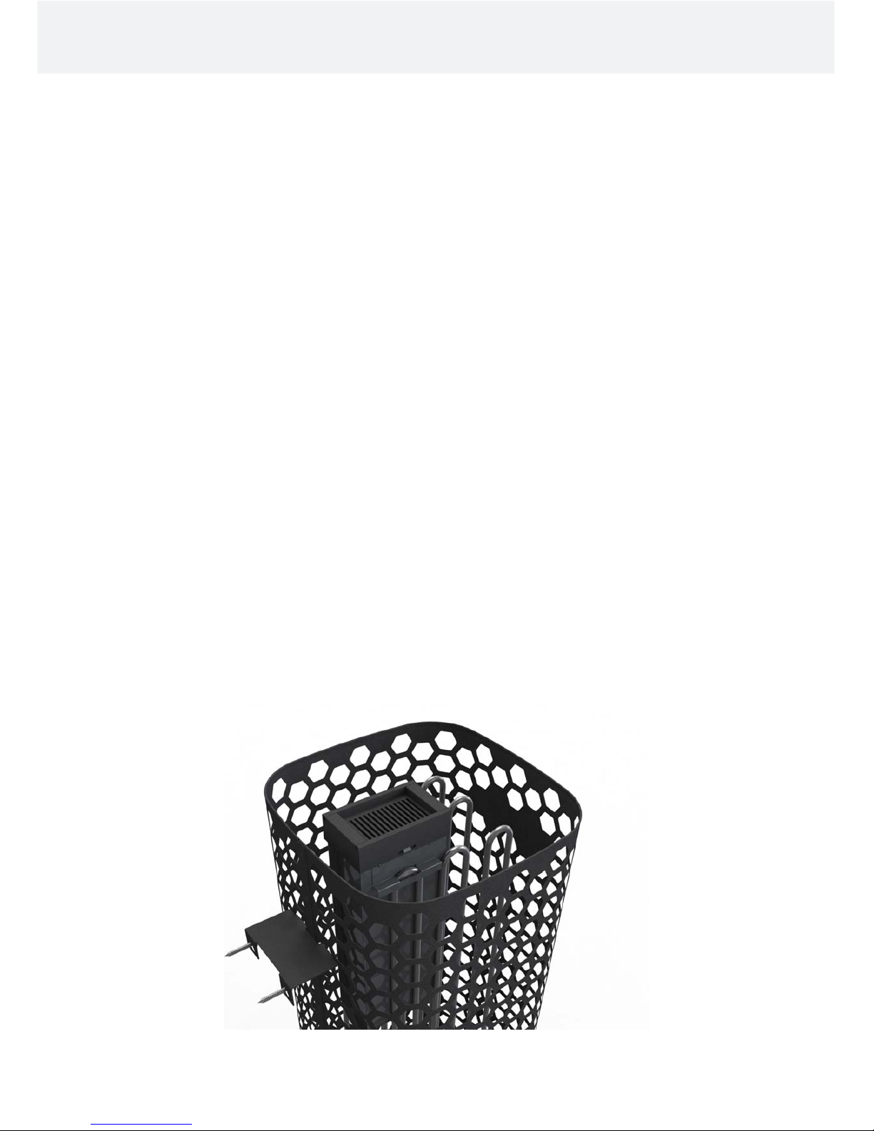
Helo Himalaya DE User manual

ELECTRIC SAUNA HEATER:
1118 – 701 – 0405
1118 – 901 – 0405
1118 – 1051 – 0405
230V – 240V 1N~ / 2~
230V 3N~
400V – 415V 3N~
CONTROL PANEL:
1601-18 (RA 18 Midi)
314 SKLT 58-3 A
Installations- och bruksanvisning Helo Ring
Installation and User Manual Himalaya DE

Contents Page
1.Quick instructions for use of the sauna heater 3
1.1. Check before taking a sauna bath 3
1.2. Operation of the sauna heater controls 3
2.Information for users 3
2.1. Sauna room 3
2.2. Recommended sauna room ventilation 4
2.3. Heating the sauna 4
2.4. Sauna heater stones 5
2.5. If the sauna heater will not heat up 6
2.6. Preparing for sauna heater installation 6
2.7. Installation 6
2.8. Sauna heater safety clearances 7
2.9. Connection of the sauna heater to the mains 8
2.10. Electric heating toggle 8
2.11. Locating the connecting box for the connection cable in the sauna room 9
2.12. Wiring diagram 10
2.13. BWT technology in a Himalaya heater 11
2.14. Principle image when 1601 – 18 (RA – 18 Midi) is used as control panel 12
3. Himalaya DE spare part list 13
4. ROHS 14
Images and tables
Figure 1 Rekommended sauna room ventilation 4
Figure 2 Safety clearances 7
Figure 3 Location for the connection box 9
Figure 4 Wiring diagram for the sauna heater 10
Figure 5 Filling the water tank 11
Figure 6 Principle image 12
Table 1 Safety clearances 7
Table 2 Connection cable and fuses 8
Table 3 Himalaya DE spare parts list 13
Installation and User Manual Himalaya DE 2

1. Quick instructions for use of the sauna heater
1.1. Check before taking a sauna bath
1. The sauna room is suitable for taking a sauna bath.
2. The door and the window are closed.
3. The sauna heater is topped with stones that comply with the manufacturer's recommendations, the heating elements are
covered with stones, and the stones are piled sparsely.
NOTE! Ceramic rocks are not allowed.
The heater's main switch is located at the bottom of the heater, on the right side as seen from the front.
The main switch is marked with a 0 – 1 sticker.
1.2. Operation of the sauna heater controls
Refer to the specific control panel operating instructions.
Rearrange the sauna stones at least once a year and replace any weathered stones. This enhances air circulation
between the stones, which extends the useful life of the thermal resistors.
If you encounter any problems, please contact the manufacturer's warranty service shop.
For additional information about enjoying a sauna bath, please visit our website at : www.helo.fi
2. Information for users
Persons with reduced physical and mental capacity, sensory handicap, or little experience and knowledge about how the
device is operated (e.g. children), should only operate the device while supervised or according to instructions given by
the persons in charge of their safety.
Make sure that children aren't playing with the sauna heater.
2.1. Sauna room
The walls and ceiling of a sauna room should be thermally well insulated. All surfaces that store heat, such as tiled and
plastered surfaces must be insulated. It is recommended to use wooden panel cladding inside the sauna room. If there
are heat storage elements in the sauna room, such as decorative stone, glass etc., note that these elements may extend
the pre-heating period even though the sauna room is otherwise well insulated (see page 6, section 2.6. Preparing for
sauna heater installation).
Installation and User Manual Himalaya DE 3

2.2. Recommended sauna room ventilation
Figure 1 Rekommended sauna room ventilation
1. Sauna room 3. Electric sauna heater 5. Exhaust flue or channel
2. Washroom 4. Exhaust valve 6. Door to the sauna room
7. A ventilation valve can be installed here to be kept closed while the sauna is heated and during bathing.
Inlet vent can be positioned in the A zone. Make sure the incoming fresh air will not interfere with (i.e. cool down) the
sauna heater's thermostat near the ceiling.
The B zone serves as the incoming air zone, if the sauna room isn't fitted with forced ventilation. In this case, the exhaust
valve is installed min 1m higher than the inlet valve.
DO NOT ISTALL INLET VALVE WITHIN ZONE C, IF THE SAUNA HEATER'S CONTROL THERMOSTAT IS LOCATED
IN THE SAME ZONE.
2.3. Heating the sauna
Before turning the sauna heater on, make sure the sauna room is suitable for taking a sauna bath. When heated for the
first time, the sauna heater may emit some odour. If you detect any odour while the sauna heater warms up, disconnect
the sauna heater briefly, and air the room. Then turn the sauna heater back on.
You should turn the sauna heater on roughly an hour before you plan to take a sauna bath, so that the stones have time to
heat up properly and the air warms up evenly in the sauna room.
Pleasant, smooth sauna bath temperature is about 70 °C.
Do not put any objects on the sauna heater. Do not dry clothes on the sauna heater or anywhere in its vicinity.
Installation and User Manual Himalaya DE 4
55
4
4
2
1
1
1
A
7
A
min
500 mm
6
3
B
3
B
C
C
C
C A
1000 mm

2.4. Sauna heater stones
Quality stones meet the following requirements:
- Sauna stones should withstand heat and heat variation caused by vaporisation of the water thrown on the
stones.
- Stones should be rinsed before use in order to avoid odour and dust.
- Sauna stones should have an uneven surface to supply a larger surface for the water to evaporate from.
- Sauna stones should be large enough, measuring about 80–120 mm to allow good ventilation between the stones.
This extends the useful life of the heating elements.
- Sauna stones should be piled sparsely in order to enhance ventilation between the stones. Do not bend the heating
elements together or against the frame.
- Rearrange the stones regularly (at least once a year) and replace small and broken stones with new, larger stones.
- Stones are piled so that they cover the heating elements. Do not, however, pile a large heap of stones on the
heating elements. For a sufficient amount of stones refer to Table 1 on page 7. Any small stones in the package of
stones must not be piled on the sauna heater.
- The warranty does not cover defects resulting from poor ventilation caused by small and tightly packed stones.
- Ceramic rocks are not allowed. They may cause damage to the sauna heater that will not be covered by the
warranty.
Installation and User Manual Himalaya DE 5

2.5. If the sauna heater will not heat up
If the sauna heater will not heat up, please check that:
- the power is on;
- the main fuses of the sauna heater are intact;
- is there any error messages on the control panel. In case of an error message on the control panel,
please refer to the control panel instructions.
THE PERSON INSTALLING THE SAUNA HEATER SHOULD LEAVE THESE INSTRUCTIONS AT THE PREMISES
FOR THE FUTURE USER.
2.6. Preparing for sauna heater installation
Check the following before installing the sauna heater.
- The ratio of the heater's input (kW) and the sauna room's volume (m3). Volume recommendations are presented in
Table 1 on page 7. The minimum and maximum volumes must not be exceeded.
- The sauna room height must be a min. of 1900 mm.
- Uninsulated and masonry stone walls extend the preheating time. Each square metre of plastered ceiling or wall surface
adds 1.2 m3to the sauna room's volume.
- Check page 8 Table 2 for a suitable fuse size (A) and the correct diameter of the power supply cable (mm²) for the
sauna heater in question.
- Conform to the specified safe clearance around the sauna heater. Please refer to page 7.
- There should be enough room around the sauna heater for maintenance purposes. Also a doorway can be considered
as a maintenance area.
2.7.Installation
Follow the safety clearance specifications on page 7 when installing the sauna heater.
The sauna heater is a floor-standing model. The base must be solid, because the sauna heater weighs about 115 kg.
The sauna heater is levelled by the adjustable legs.
The sauna heater needs to be fixed directly onto the wall or to the sauna bench module by using the provided metal rack
to make sure the safety distances will be maintained in use.
Walls or ceilings must not be clad with fibre-reinforced plaster board or other light-weight cladding, because they may
cause a fire hazard.
Only a single sauna heater is allowed per sauna room.
Wall support of the heater and water tank installation.
Installation and User Manual Himalaya DE 6

2.8. Sauna heater safety clearances
Table 1 Safety clearances
Corner and wall installation: The sensor OLET 19 must be installed to ceiling in the side-line to the out side
from line. See the picture.
A 330 D
1030
870
1900
H
60
A
helo
NOTE !
Mid-floor installation: If the heater is placed more than 60 mm from the wall the installation type is always a
mid-floor installation. The heater must be attached to the benches or to a similar structure using a wall support.
helo
F
870
A A
H
1900
mm
Figure 2 Safety clearances
Effect Saunaroom Minimum distance to Stone
kW
Volume Height Side
wall
A
mm
In front
of
D
mm
Ceiling
mm ca. kg
min.
m³
max.
m³ min. mm
6,8 5 9 1900 60 60 870 100
9,0 8 13 1900 60 60 870 100
10,5 9 15 1900 60 60 870 100
Installation and User Manual Himalaya DE 7
Water tank
Wall support
attaching the
heater to the
wall or benches
Wall support
attaching the
heater to the
wall or benches
Wall
support
attaching
the heater
to the wall
or benches
NOTE! an absolute measure
Sensor
OLET 19
Sensor OLET 19
Sensor OLET 19

2.9. Connection of the sauna heater to the mains
The sauna heater must be connected to the mains by a qualified electrician and in compliance with current regulations.
The sauna heater is connected with a semi-permanent connection. Use H07RN-F (60245 IEC 66) cables or a
corresponding type. Other output cables (signal lamp, electric heating toggle) must also adhere to these
recommendations. Do not use PVC insulated cable as a connection cable for the sauna heater.
A multipolar (e.g. 7-pole) cable is allowed, if the voltage is the same. In the absence of a separate control current fuse, the
diameter of all cables must be the same, i.e. in accordance with the front fuse.
The connecting box on the sauna wall should be located within the minimum safety clearance specified for the sauna
heater. The maximum height for the connection box is 500 mm from the floor. See page 9 Location the connection box
Power
kW
Sauna heater’s
connection cable
H07RN –F/ 60245
IEC 66
mm²
400V 3N~
Fuse
A
Sauna heater’s
connection cable
H07RN –F/ 60245
IEC 66
mm²
230V 3~
Fuse
A
Sauna heater’s
connection cable
H07RN –F/ 60245
IEC 66
mm²
230V 1 N~ / 2~
Fuse
A
6,8 5 x 1,5 3 x 10 4 x 4 3 x 20 3 x 6 1 x 35
9,0 5 x 2,5 3 x 16 4 x 6 3 x 25 3 x 10 1 x 50
10,5 5 x 2,5 3 x 16 4 x 6 3 x 35 ---------- --------
Table 2 Connection cable and fuses
If the connection box is located at over 500mm distance from the heater, the maximum height is 1000mm from the floor.
Sauna heater insulation resistance:
The sauna heater heating elements may absorb moisture from air, e.g. during storage. This may cause leakage currents.
The moisture will be gone after a few heating sessions. Do not connect the heater power supply through a ground fault
interrupter.
However, adhere to the effective electrical safety regulation when installing the sauna heater.
2.10. Electric heating toggle
Electric heating toggle applies to homes with an electric heating system.
Sauna heater has connections (marked N-55) for controlling the electric heating toggle. Connectors N-55 and the heating
elements are simultaneously live (230V). The sauna heater thermostat also controls the heating toggle. In other words,
home heating turns on once the sauna thermostat cuts power off the sauna heater.
Installation and User Manual Himalaya DE 8

2.11. Locating the connecting box for the connection cable in the sauna room
60mm = Specified minimum safety clearance
1. Recommended location for the connecting box
2. Silumin box recommended in this area.
3. This area should be avoided. Always use a silumin box.
In other areas, use a heat-resisting box (T 125 °C) and heat-resisting cables (T 170 °C). The connection box must be
clear of obstacles. When installing the connection box to zones 2 or 3, refer to the instructions and regulations of the
local energy supplier.
200 mm
60 60
3.
2.
1.
500 mm
500 mm
helo
Figure 3 Location for the connection box
Installation and User Manual Himalaya DE 9

2.12. Wiring diagram
1. Syöttö / Nätet / Stromnetz / Power input/ Stroomaansluiting / Puissance absorbée /
Leejas jauda / Toide / Wejœcie zasilania /
2. Saunavalo / Bastu belysning / Saunabeleuchtung / Sauna light. max 100W /
Sauna icht max. 100W / Am poule du sa un a max. 100 W / Sauna swiatla max 100W
Pirts apgaismojums maks imali 1 00W / Saunalamp /
3. Tuuletin / Fläkt / Ventilator / Fan ma x 100W / Ventilator max. 100W / Wentylator
Ventilateur max. 100 W / Ventilators Maks. 100 W / Ventilaator /
4. Sähkölämmityksen vuorottelu/ El.förregling av annan el. förbrukare/
Interrupteur du chauff age électrique / contact de signa l / Signal kontakt /
Signal contact / Wisselschakelaar elektrische verwarm ing, /
signaalcontac t. Signalkontakts / Elektrikütte kontakt / Sterowanie ogrzewaniem elektrycznym
5. Ohjauskeskus / Styrpanel / Steuergerät / Control panel / Bedieningspaneel / Tablede commande /
/ Vadibas pults / Juhtimiske skus /
6. Tuntoelin / Sensor / Fühler / Sensor / Capteur / Devejs / Andur / Czujnik / 354 SKLT 14 A
- Katso ohjauskeskuksen käyttöohje
- Se styrpanelens bruksan visning
- Sehe die Bedienungsanleitung des
Steuergerätes
- See the control panel manual
- Z ie de ge br ui ksh a ndl eid ing van h et
bedieningspaneel
- Reportez-vous aux instructions de
fonctionnement du tableau de commande.
- Sk. Vadibas pults instrukciju
-
-
*)
Пульт управления
/
Panel sterując
y
Д
атчик
Входное напряжение
сигнала контак
т
Patrz po drêcznik p ane lu stero wania
Са уна свет. ма кс 100W
Венти л ят ор Макс 100W
Teho, Effekt
Input, Potencia
Leistung, Moc
Vöimsus,Wejscie
Puissance
Lämpövastukset, Värmeelement, Tennid, Heating elements,
Heizeelement, Resistores Térmicos, Éléments chauffants,
Elementy grzewcze, Kütteelement,
Входное
напряжение
ТЭНы,
kW
6,8
9,0
10,5
230 V
SEPC 226 SEPC 230 SEPC 228
2267W 3000W 3500W
1,2,3
1A 1A
N
L
L L L
1 2 3
A 1 23 4 5 B 1 2 3 4 5 1 2 3 4
J10 J11 J12
Light Fan
Control
U V W
2
3
1
1 2 3 4
3 41 2
1.
5.
4.
1,2,3
N N N 55
3.
2.
1 2 3 4 5 6
6.
*)*)
*)
*)
12 3 6
4 5
230 V 3~
L1 L2 L3
N
12 3 6
4 5
400V - 415V 3N~
L1 L2 L3
K1
K2
T1 AH
F1
1=Sin,Blå,Blau,Blue
2=Val,Vit,WeiB,White
3=Pun,Röd,Rod,Red
4=Kelt,Gul,Gelb,Yellow
1,2,3
T3,15 AH
F2
12 3 6
4 5
230V - 240V 1N~ / 2~
N L2
Max. 9,0 kW
Смoтpитe инс трукци ю. кпу льт y управл ения
Figure 4 Wiring diagram for the sauna heater
Installation and User Manual Himalaya DE 10

2.13. BWT technology in a Himalaya heater
BWT technology uses the heater's thermal energy to heat water and raise the moisture level without a separate
heat source. Moisturised air improves the sauna climate, and various fragrances and salts can be evaporated to
make the sauna experience more enjoyable.
A water tank with a lid is delivered with the heater; the tank can be installed in the wider gap between the heating
elements. The water tank can be installed when approximately 2/3 of the heater stones have been stacked. The water
tank, even when empty, does not need to be removed when the heater is on.
The tank has a capacity of approximately two litres. Bringing water to the boil when the tank is full takes approximately 1-
2 hours depending on the set temperature.
It is recommended to pour water into the tank when the heater is turned off. Water is poured through the grate on the lid.
You can pour less water into the tank if the bathing time is shorter.
The water tank must be removed and impurities, such as limescale etc. removed every so often. The stones surrounding
the tank must be removed during cleaning, so that the tank can be lifted more easily.
When the water is boiling, the moisture levels in the sauna remain high. This means that the temperature can be kept
lower while still experiencing pleasant heat. More heat and moisture can, if necessary, be created by throwing water on
the stones on top of the heater.
Mild fragrance essences, suitable for heater use, can be put in the water tank.
You can, for example, put mountain salt crystals on the lid of the water tank. They dissolve into the steam and evaporate
into the air. If mountain salt crystals are placed in the water tank, the salinity of the water will remain 26%.
Figure 5 Filling the water tank
Installation and User Manual Himalaya DE 11
Mountain salt crystals on the
grate of the water tank.
Filling the water tank with water

2.14. Principle image when 1601 – 18 (RA – 18 Midi) is used as control panel
helo
OK
Figure 6 Principle image
Installation and User Manual Himalaya DE 12
1= Blue
2= White
3= Red
4= Yellow
Heater
Sensor cable
Control panel
RA – 18 (Midi 18)
PCB OLEA 57
4 x 0,15 mm
2
Sensor OLET 19
Sauna heater
NOTE!
See more detailed
installation
instructions
in the control panel
operating
instructions
Water containe
r
Silicone 4 x 0,25
Principle image
4
3
2
1
4
3
2
1
PCB
OLEA 57
Sensor OLET 19
Limiter overtemperature return
OK
A 1 2 3 4 5 B 1 2 3 4 5
1 2 3 4
J1J2
J11
J10
Communication
PCB OLEA 83
1= Brown
2= White
3= Green
4= Yellow
Control panel
1601 - 18
RA – 18 (Midi 18)
Input
230V – 240V 1N~ / 2~
230V 3~
400V – 415V 3N~

3. Himalaya DE spare part list
Table 3 Himalaya DE spare parts list
Part Part number Part name Himalaya
70 DE
Himalaya
90 DE
Himalaya
1051 DE
1 7712000 Cable clamp 1 1 1
2 7812550 Mains connector NLWD 1-1 1 1 1
3 5916229 Circuit board OLEA 57 1 1 1
4 6216410 Communication PCB OLEA 83 1 1 1
5 5716203 Relay Finder 1 1 1
6 7801711 Fuse 1 AT 1 1 1
7 7817536 Fuse holder 1 1 1
8 6101741 Rocker switch OAAA 2 1 1 1
9 7306008 Rubber cover for rocker switch 1 1 1
10 5200719 Heating element SEPC 226
2267W/230V 3
10 5200721 Heating element SEPC 230
3000W/230V 3
10 5200720 Heating element SEPC 228
3500W/230V 3
Installation and User Manual Himalaya DE 13

4. ROHS
Ympäristönsuojeluun liittyviä ohjeita
Tämän tuotteen käyttöiän päätyttyä sitä ei
saa hävittää normaalin talousjätteen
mukana, vaan se on toimitettava
sähkö- ja elektroniikkalaitteiden kierrätykseen
tarkoitettuun keräyspisteeseen.
Symboli tuotteessa,
käyttöohjeessa tai
p
akkauksessa tarkoittaa sitä.
Valmistusaineet ovat kierrätettävissä merkintänsä
mukaan. Käytettyjen laitteiden
uudelleenkäytöllä, materiaalien hydöyntämisellä
tai muulla uudelleenkäytöllä teet arvokkaan teon
ympäristömme hyväksi.
Tuote palautetaan ilman kiuaskiviä ja verhouskiviä
kierrätyskeskukseen.
Tietoa kierrätyspaikoista saat
kuntasi palvelupisteestä.
Anvisningar för miljöskydd
Denna produkt får inte kastas med
vanliga hushållssopor när den
inte längre används. Istället ska den
levereras till en återvinningsplats
för elektriska och elektroniska apparater.
Symbolen på produkten,
handboken eller
förpackningen refererar till detta.
De olika materialen kan återvinnas enligt
märkningen på dem. Genom att återanvända,
nyttja materialen eller på annat sätt återanvända
utsliten utrustning, bidrar du till att skydda vår
miljö.
Produkten returneras till återvinningscentralen
utan bastusten och eventuell täljstensmantel.
Vänligen kontakta de kommunala myndigheterna
för att ta reda på var du hittar närmaste
återvinningsplats.
Instructions for environmental protection
This product must not be disposed with
normal household waste at the end of
its life cycle. Instead, it should be
delivered to a collecting place for the recycling
of electrical and electronic devices.
The symbol on the product, the
instruction manual or the
p
ackage refers to this.
The materials can be recycled according to the
markings on them. By reusing, utilising the
materials or by otherwise reusing
old equipment, you make an important
contribution for the protection of our environment.
Please note that the product is returned to the
recycling centre without any sauna rocks and
soapstone cover.
Please contact the municipal administration
with enquiries concerning the recycling place.
Hinweise zum Umweltschutz
Dieses Produkt darf am Ende seiner Lebens-
Dauer nicht über den normalen Haushaltsabfall
Entsorgt werden, sondern muss an einem
Sammelpunkt für das Recycling von elektrischen
und elektronischen Geräten abgegeben werden.
Das Symbol auf dem produkt, der
Gebrauchsanleitung oder der
Verpackung weist darauf hin.
Die Werkstoffe sind gemäß ihrer Kennzeichnung
wiederverwertbar, Mit der Wiederverwendung,
der stofflichen Verwertung oder anderen Formen
der Verwertung von Altgeräten leisten Sie einen
wichtigen Beitrag zum Schutze unserer Umwelt.
Dieses Produkt soll ohne Steine und
Specksteinmantel an dem Sammelpunkt für
Recycling zurückgebracht werden.
Bitte erfragen Sie bei der Gemeindeverwaltung
die zuständige Entsorgungsstelle.
Installation and User Manual Himalaya DE 14
Other manuals for Himalaya DE
1
Table of contents
Other Helo Heater manuals

Helo
Helo Rocher Pure User manual

Helo
Helo Helo-WT Laava User manual

Helo
Helo FONDA DET User manual

Helo
Helo Ring1118-600-0405 User manual

Helo
Helo 1107-60-040511 User manual

Helo
Helo 1712-45-171817 Operator's manual

Helo
Helo 1712-45-1706 User manual

Helo
Helo RONDO User manual

Helo
Helo Roxx Elite User manual

Helo
Helo Roxx Elite User manual

Helo
Helo 1712-60-171817 User manual

Helo
Helo Viki Series User guide

Helo
Helo Laine D Series User manual

Helo
Helo Hanko D User manual

Helo
Helo HAVANNA D User manual

Helo
Helo 1106 - 901 User manual

Helo
Helo Mini SA 1050216 User manual

Helo
Helo MAGMA User manual

Helo
Helo Vienna 450 D User manual

Helo
Helo LAINE STJ User manual