Helvi GALILEO 175 User manual

INSTRUCTIONS MANUAL
MANUALE DI ISTRUZIONI
MANUAL DE USO Y MANUTENCIÓN
MANUEL D’INSTRUCTIONS ET D’ENTRETIEN
BETRIEBSANLEITUNG
ИНСТРУКЦИЯ ПО ЭКСПЛУАТАЦИИ
MANUAL DE INSTRUÇÕES
PLEASE READ THESE INSTRUCTIONS BEFORE INSTALLING, OPERATING, OR
SERVICING THIS PRODUCT. DO NOT DESTROY THIS MANUAL.
LEGGETE LE ISTRUZIONI PRIMA DI INSTALLARE, UTILIZZARE O RIPARARE
QUESTO IMPIANTO. CONSERVATE QUESTO MANUALE.
LEAN LAS INSTRUCCIONES ANTES DE INSTALAR, UTILIZAR O REPARAR
ESTOS APARATOS. CONSERVEN ESTE MANUAL.
LIRE CES INSTRUCTIONS AVANT L’INSTALLATION, L’UTILISATION OU LA
REPARATION DE CET APPAREIL. NE PAS JETER LE PRÉSENT MANUEL.
LESEN SIE DIESE ANLEITUNG VOR DER INSTALLATION, DEM BETRIEB ODER
DER WARTUNG DIESES PRODUKTS. NICHT ZERSTÖREN SIE DIESES HANDBUCH.
ПОЖАЛУЙСТА, ВНИМАТЕЛЬНО ПРОЧИТАЙТЕ ДАННУЮ
ИНСТРУКЦИЮ ПЕРЕД УСТАНОВКОЙ, ЭКСПЛУАТАЦИЕЙ ИТЕХНИЧЕСКИМ
ОБСЛУЖИВАНИЕМ АППАРАТА. СОХРАНИТЕ ИНСТРУКЦИЮ.
LEIA AS INSTRUÇÕES ANTES DE INSTALAR, USAR OU CONSERTAR ESTE
EQUIPAMENTO. CONSERVE ESTE MANUAL.
77611266
WELDING INVERTERS
INVERTER DI SALDATURA
INVERTER DE SOLDADURA
ONDULEURS
SCHWEISSINVERTER
СВАРОЧНЫЕ ИНВЕРТОРЫ
INVERSOR DE SOLDA

2

3
IMPORTANT
CAREFULLY READ THE FOLLOWING
INSTRUCTIONS BEFORE INSTALLING
THE UNIT AND MAKE SURE THAT THE
YELLOW AND GREEN GROUNDING
CONDUCTOR IS DIRECTLY CONNEC-
TED TO THE GROUND IN THE WELDING
LOCATION./
THE UNIT MUST NEVER BE OPERATED
WITHOUT PANELS AS THIS COULD BE
DANGEROUS FOR THE OPERATORAND
COULD CAUSE SERIOUS DAMAGE TO
THE EQUIPMENT.
THE UNIT WORKS ONLY WITH INPUT
VOLTAGE OF 230Vac -50 Hz-1Ph.
THE INPUT CABLE IS ENERGIZED EVEN
WHEN THE MAIN SWITCH IS ON THE “0”
POSITION. THEREFORE, BEFORE SER-
VICING THE EQUIPMENT, MAKE SURE
THAT THE 2 POLE PLUG IS DISCON-
NECTED FROM THE LINE SOCKET.
THIS WELDER CAN BE USED ONLY
WITH DIESEL GENERATING SETS WITH
POWER HIGHER THAN 6 KVA AT 220 V
50 HZ. (except for units supplied at 110V)
1.0 INTRODUCTION
1.1 EQUIPMENT IDENTIFICATION
The unit’s identification number (specification
or part number) model, and serial number
usually appear on a nameplate attached to
the rear panel. Equipment which does not
have a control panel such as gun and cable
assemblies is identified only by the specifica-
tion or part number printed on the shipping
container. Record these numbers for future
reference.
1.2 RECEIPT OF EQUIPMENT
When you receive the equipment, compare
it with the invoice to make sure it is complete
and inspect the equipment for possible dama-
ge due to shipping. All machines dispatched
have been scrupulously checked. However,
should your machine not work properly, con-
sult the section on TROUBLE SHOOTING in
this manual. If the fault persists, consult your
authorized dealer.
2.0 SAFETY WARNING
2.1 GENERAL INSTRUCTIONS
This manual contains all the necessary in-
structions for:
- the installation of the equipment;
- a correct operating procedure;
- an adequate maintenance of the equipment.
Therefore, be sure this manual is carefully
read and understood by the maintenance
and technical operators.
2.2 LOCATION
Welding processes of any kind can be dange-
rous not only to the operator but to any person
situated near the equipment if safety and opera-
ting rules are not strictly observed.
Therefore the owner and the operator must
be aware of all possible risks so that they
may take the necessary safety precautions to
avoid any kind of accident at work.
The main precautions to be observed are:
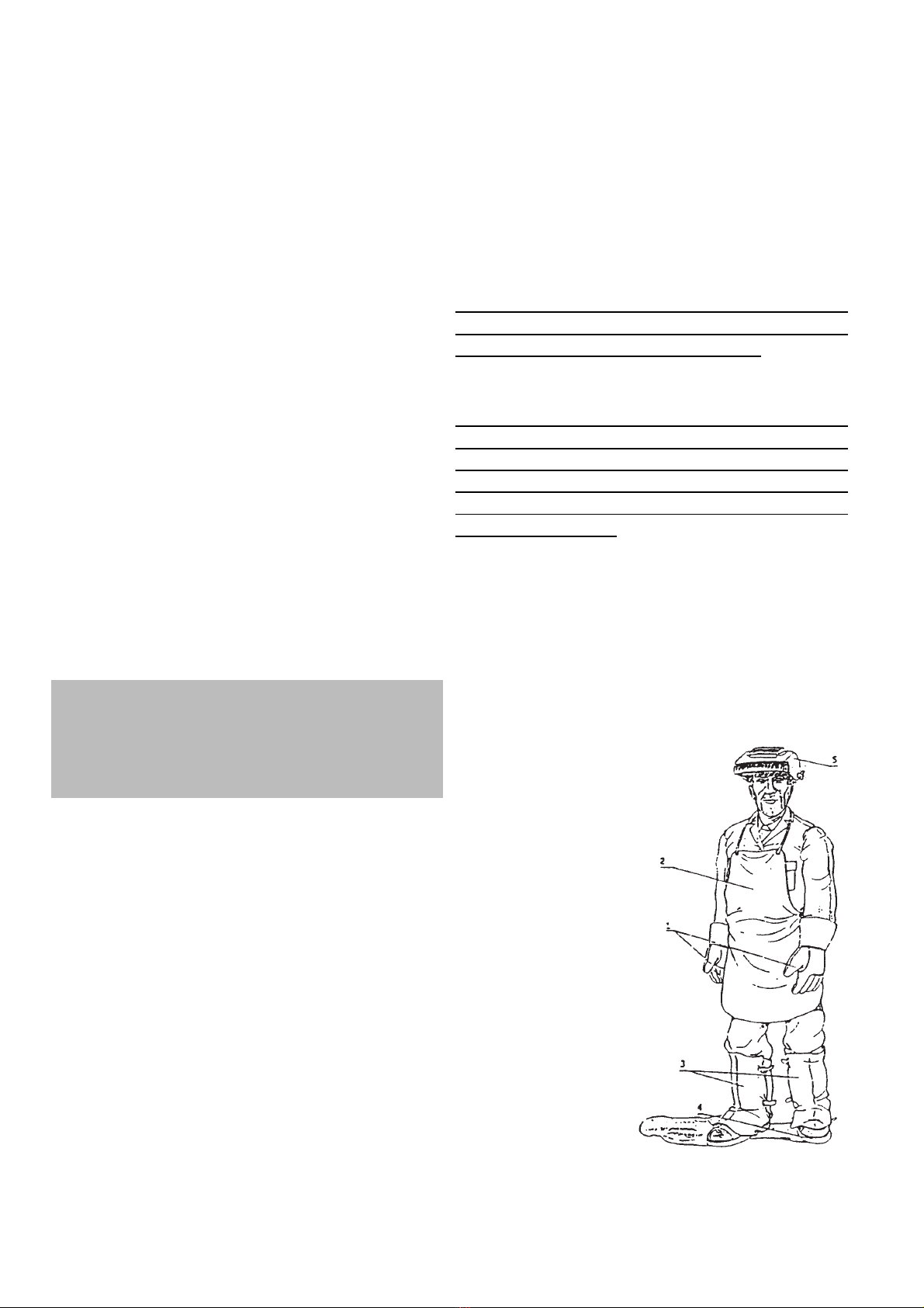
- Operators should protect their body by
wearing non flam-
mable, close fitting
protective clothing,
without pockets or
turned-up trousers.
Oil or grease should
be carefully removed
from all articles, be-
fore wearing. Ope-
rators should also
wear closed safety
boots with steel toe
caps and with rubber
soles ( Fig. 1).
1. Leather gloves
2. Leather aprons
3. Shoes Cover
4. Security shoes
5. Face mask
- Operators should wear a non- flammable
welding helmet or face shield designed so as
to shield the neck and the face, also on the
sides. The helmet or the face shield should
be fitted with protective glasses adequate to
the welding process and current used. Glass
screens must always be kept clean, and im-
mediately replaced if they are broken or cra-
cked (Fig.2). It is good practice to install a
pane of transparent glass on top of the adiac-
tinic glass, between it and the welding area.

4
This pane can be frequently replaced when
incandescent spatters and deposits greatly
reduce visibility. When working with coated
plates that emit toxic fumes when heated,
use an air-supplied respirator.
- Welding should be done in a closed area
that does not open onto other working areas,
in order to protect all workers against radia-
tion and fumes. If such an area cannot be
provided, the welding area must be delimi-
ted by protective screens painted in opaque
black large enough to restrain the visibility of
any person situated near the area (Fig. 3).
- Remove all chlorinated solvents from the
welding area before welding. Certain chlori-
nated solvents decompose when exposed to
ultraviolet radiation to form phosgene gas.
- Never, under any circumstances, look at
an electric arc without suitable eye protection
(Fig. 4).
- Always wear protective goggles with tran-
sparent lenses to prevent splinters or other
foreign particles from harming the eyes (Fig.
5).
- Adequate local exhaust ventilation must
be used in the area. It should be provided
through a mobile hood or through a built-
in system on the workbench that provides
exhaust ventilation from the sides, the front
and below, but not from above the bench so
as to avoid raising dust and fumes. Local
exhaust ventilation must be provided toge-
ther with adequate general ventilation and
air circulation, particularly when work is done
in a confined space. (Fig.6). Any symptom of
stain or soreness to the eyes, the nose or the
throat may be cause by inadequate ventila-
tion; work must be stopped immediately and
all necessary steps must be taken to provide
adequate ventilation.
- Welding process must be performed on
metal coatings thoroughly cleaned from la-
yers of rust or paint, to avoid production of
harmful fumes. The parts degreased with a
solvent must be dried before welding.
- Do not weld metal or painted metal con-
taining zinc, lead, cadmium or beryllium un-
less the operator, or anyone else subjected to
the fumes, is wearing respiratory equipment
or an air-supplied helmet.

5
- Technical and sanitary protection of all wel-
ding operators-directly or indirectly involved
in welding processes is provided by the regu-
lations in force for sanitation and prevention
of employment related injuries.
2.3 SAFETY INSTRUCTIONS
For your safety, before connecting the source
to the line, closely follow these instructions:
- an adequate two-pole switch must be in-
serted before the two-pole main outlet; this
switch must be equipped with time-delay fu-
ses and it must match the data specified in
the chapter “Technical Specification”;
- the mono-phase connection with ground
must be made with a two-pole plug compati-
ble with the above mentioned socket;
- two wires of the two-pole input cable are
used for the connection with the mono-phase
line and the yellow-green wire for the compul-
sory connection to the ground in the welding
location;
- connect all the metal parts which are near
the operator in the welding location by using
cables bigger or of the same cross section of
the welding cable to a ground terminal;
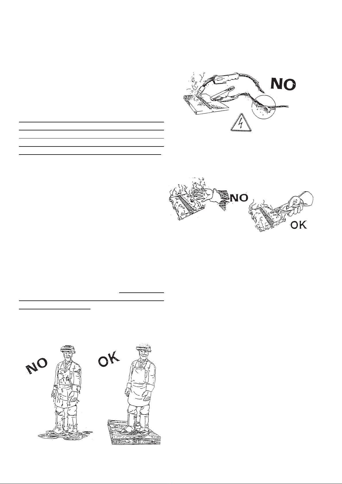
- when working in a confined space, the po-
wer source must be kept outside the welding
area and the ground cable should be welded
to the workpiece; do not work in a damp or
wet area in these conditions (Fig. 7).
- do not use damaged welding or input ca-
bles (Fig. 8);
- the operator should never touch, with any
part of his body, high temperature or electri-
cally hot metal parts (Fig. 9);
- the operator should never wind the wel-
ding cables around his body;
- the welding gun should never be pointed
at the operator or at another person. The po-
wer source has a protection level IP 22; the-
refore, it prevents:
- any manual contact with hot or moving in-
ternal parts;
- the insertion of any solid body with more
than 12mm diameter;
- protected against vertically falling drops
of water (condensation) with inclination max
of 15°.
The source must never be operated without
its panels; this could cause serious injury to
the operator and could damage the equip-
ment itself.
2.4 FIRE PREVENTION
The working area should conform to the
Safety Regulations, and therefore, fire ex-
tinguishers should be provided in the area
and walls, ceiling and floor should be non-
flammable. All combustible material must
be moved from the welding area (Fig. 10). If
combustibles cannot be moved, they must be
protected with fire-resistant cover. Ventilate
potentially flammable atmospheres before
welding. Never operate in an atmosphere
which contains heavy concentrations of dust,
flammable gas or combustible liquid vapor.
The power source must be located in a safe
area with a firm and flat floor; it should not be
put against a wall. Do not weld containers in
which fuel, lubricant or any other flammable
material have been stored. After having com-

6
pleted your work, always check that the area
is free of glowing or smoldering material.
2.5 SHIELDING GAS
Use the correct shielding gas for the welding
process. Be sure that the regulator/flowmeter
mounted on the cylinder is working well.
Remember to keep away the cylinder from
any source of heat.
2.6 PERMITTED NOISE LEVELS 86/188/
EEC RULE.
Under normal circumstances the equipment
used for electric arc welding does not exce-
ed the permitted 80 dBA. However in cer-
tain conditions eg. high welding parameters
in confined spaces, noise levels may exce-
ed the permitted level. For this reason it is
strongly recommended that operatives wear
appropriate ear protection.
2.7 ELECTROMAGNETIC
COMPATIBILITY.
Before installing the STICK/TIG welding unit,
carry out an inspection of the surrounding
area, observing the following guidelines:
1- Make sure that there are no other power
supply cables, control lines, telephone leads
or other equipment near the unit.
2- Make sure that there are no radio recei-
vers or television appliances.
3- Make sure there are no computers or other
control systems.
4- Make sure that there is no-one with a pa-
cemaker or hearing aid in the area around
the unit.
5- Check the immunity of any other equipment
operating in the same environment.
In certain cases additional protective measu-
res may be required.
Interference can be reduced in the following
ways:
1- If there is interference in the power sup-
ply line, an E.M.C. filter should be inserted
between the mains and the unit.
2- The output cables of the unit should be
shortened; these should be kept close toge-
ther and stretched along the ground.
3- All the panels of the unit should be correct-
ly closed after carrying out maintenance.
2.8 Medical and first aid treatment
First aid facilities and a qualified first aid per-
son should be available for each shift for im-
mediate treatment of electrical shock victims.
A medical facility should be close by for im-
mediate treatment of flash burns of the eye
and skin burns.
EMERGENCY FIRST AID:
Call physician and ambulance immedia-
tely.
Use First Aid techniques recommended
by The Red Cross.
DANGER: ELECTRIC SHOCK CAN BE
FATAL
If person is unconscious and electric
shock is suspected , do not touch the
person if he or she is in contact with wel-
ding equipment, or other live electrical
parts. Disconnect (open) power at wall
switch and then use First Aid. Dry wood,
wooden broom, or other insulating mate-
rial can be used to move
cables, if necessary, away from the per-
son.

7
3.0 BRIEF INTRODUCTION
Your welder belongs to a range of welding
inverters for MMA - Manual Metal Arc Wel-
ding that adopts the latest pulse width mo-
dulation (PWM) techology and the insulated
gate bipolar transistor (IGBT) power module
to grant optimal performances: constant cur-
rent output to make welding arc more stable
and stepless current regulation. All inverters
are fitted with automatic protection functions:
overvoltage, overcurrent and overtemperatu-
re.
3.1 TECHNICAL DATA
NOTE: here below data may differ from
the data on the technical table on the unit.
Always refer to the technical data table on
the unit.
4.0 INSTALLATION OF THE
EQUIPMENT
Proper operation of the generator is ensu-
red by adequate installation. The assem-
bly of the inverter must be done by expert
people, following the instructions and in
full respect of the safety standards.
- Remove the welder from the carton box.
BEFORE ATTEMPTING ANY ELECTRI-
CAL CONNECTION CHECK THE DATA
PLATE AND MAKE SURE THAT THE IN-
PUT VOLTAGE AND THE FREQUENCY
ARE THE SAME OF THE MAINS OUTLET
TO BE USED.
EARTHING
- To protect users the welding machi-
nes must be connected properly to the
earth (ground) system (INTERNATIONAL
SAFETY REGULATIONS).
- It is indispensable to earth (ground)
the machine properly with the yellow-
green conductor of the power supply ca-
ble, in order to avoid discharges due to
accidental contacts with earthed objects.
- The chassis (that is conductive) is
electrically connected to the earth con-
ductor. Failure to earth the equipment
correctly can cause electric shocks dan-
gerous to the users.
- Plug the inverter to the mains.
Do not use the generator with input ca-
bles’ extensions longer than 10m and
thinner than 2.5mm². Remember to keep
them layed and not wound or entangled.
Do not use the welder with the side panels
partially or completely removed in order
to avoid accidental contacts with inner
live parts.
- The inverter is now ready for use. Make
sure you are welding in a properly ventilated
area and that the ventilation openings of the
machine are not obstructed (poor air ventila-
tion may reduce the duty cycle of the unit and
cause damages). Now you may choose the
welding process by connecting the accesso-
ries as showed in the following pages.
100 Amps 130 Amps
- A 130 Amps
- B
(1 ph)
230V
50/60Hz 230V
50/60Hz 230V
50/60Hz
Power 60% KVA
2,4 2,7 2,7
Uo V
60 60 60
Amp.Min-Max A±10%
5 ÷ 100 5 ÷ 130 5 ÷ 130
Amp. 60974-1 A
15% 100
60% 50 15% 130
60% 65 20% 130
60% 75
ØEmm
1,6 ÷ 2,5 1,6 ÷ 3,25 1,6 ÷ 3,25
Insulation -
HHH
Protec. Degree -
IP22 IP22 IP22
160 Amps 160 Amps DV
(1 ph)
230V
50/60HZ 115V 230V
Power 60% KVA
4,2 3,8 4,2
Uo V
65 65 65
Amp.Min-Max A±10%
5 ÷ 160 5 ÷ 140 5 ÷ 160
Amp.
60974-1 A
30% 160
60% 115 35% 140
60% 105 30% 160
60% 115
ØEmm
1,6 ÷ 4 1,6 ÷ 3,25 1,6 ÷ 4
Insulation -
HH
Protec. Degree -
IP22 IP22
200 Amps
(1 ph)
230V 50/60Hz
Power 60% KVA
6
Uo V
65
Amp.Min-Max A±10%
5 ÷ 200
Amp. 60974-1 A
25% 200 60% 160
ØEmm
1,6 ÷ 5
Insulation -
H
Protec. Degree -
IP22

8
5.0 INVERTER FUNCTIONS AND
CONNECTIONS
1 Adjusting welding current potentiome-
ter
2 Stick / Tig Selector (only for the mo-
dels which have it)
3 Green Led indicating power ON
Led ON = Power ON
Led OFF = Power OFF
Overvoltage Protection Intervention (reset
the unit by switching it OFF, wait 20 seconds,
then switch the unit ON)
4 Yellow Led
Led ON = indicating temperature limits are
exceeded.
Warning: Let unit to cool down. When ready,
the orange led will automatically shut off.
Led ON = indicating alarm condition due to
overcurrent. Turn unit off and then on. In the
case of protection intervention due to a cur-
1
2
5
6
34
rent peak the unit will revert to working, if not
so, please contact yr service centre.
5 dinse positive socket
6 dinse negative socket
7 Input Cable
8 ON/OFF Switch
6.0 STICK WELDING
General information
The electric arc may be described as a
source of bright light and strong heat;
in fact, the flow of electric current in the
gas atmosphere which surrounds the
electrode and the workpiece determines
the radiation of electromagnetic waves
that can be perceived as light and/or
heat depending on their wave length. At
an unperceivable level, the arc also pro-
duces ultra-violet and infra-red light; io-
nizing rays have never been noted. The
heat produced by the arc is used in the
welding process to melt and join metal
parts. The necessary electric current is
supplied by special equipment common-
ly called welding machine.
- Connect the earth cable to the negative
pole of the Inverter and the earth clamp to the
workpiece.
- Connect the welding cable to the positive
pole of the Inverter.
- Select the welding current using the poten-
tiometer on the front panel. The welding cur-
rent should be chosen following the instruction
given by the electrodes manufacturer on the
electrode box, but the following indications
may be useful as general information:
- Switch the Inverter on. The two leds on
the front panel will be respectively the green
= lit and the yellow = off (for more details see
page before). Select the stick welding throu-
gh the switch placed on the front panel.
RETEMAIDEDORTCELETNERRUCGNIDLEW
mm5.1A04-A03
mm0.2A56-A05
mm5.2A001-A07
mm52.3A041-A001
mm0.4A061-A041
8
7

9
- Protect your face with a mask or a helmet.
Touch, with the electrode fastened, in the
electrode holder, the work piece until the arc
will be struck. (the inverter is featuring “hot
start” to improve the striking.
Avoid hammering the workpiece with the
electrode since it may loose the coating
and increase the arc striking difficulties.
- After striking the arc keep feeding the
electrode into the weld pool with an angle of
about 60° and moving left to right so that you
may control visually the welding. The length
of the arc can also be controlled by lifting or
lowering slightly the electrode. Also a varia-
tion of the welding angle may increase the
size of the weld pool improving the capacity
of surfacing of the slag.
- At the end of the weld let the slag cool off
before removing it, using the brush-hammer.
CAUTION:
Protect your eyes when hitting the slag
with the chip hammer to avoid damages.
CAUTION:
A bad start can be due to the dirty wor-
kpiece, a bad connection between earth
cable and work piece, or the bad faste-
ning of the electrode in the electrode
holder.
7.0 QUALITY OF THE WELD
The quality of the weld will depend mainly on
the ability of the welder, on the type of weld
and on the quality of the electrode: Choose
the proper electrode before attempting to
weld, paying attention to the thickness and
composition of the metal to be welded.
Correct welding current.
If the current is too high the elctrode will burn
fast and the weld pool will be wide irregula-
rand difficult to be controlled. If the current is
too low you will lack power and the weld pool
will be narrow and irregular.
Correct arc length.
If the arc is too long it will cause spatters and
small fusion of the welding piece. If the arc is
too short the arc heat will be insufficient cau-
sing the electrode to stick to the workpiece.
Correct welding speed.
The correct welding speed will consent to
achieve a weld of proper width, without wa-
ves or craters.
8.0 TIG WELDING
The TIG process uses the electrical arc
struck between the tungsten electrode of the
torch and the work piece surface.
In TIG welding the torch is always con-
nected to the negative pole of the welder.
Welder preparation:
- Select TIG welding thru the Selector on
the front panel.
- Connect the earth cable to the positive
pole of the welder and the earth clamp to the
work piece.
- Connect the TIG torch to the negative
pole of the welder and the gas hose to the
pressure regulator of the gas cylinder.
The flow of the gas is manually control-
led using the knob on the torch handle.
Use inert gas (argon ) only.
- Turn the inverter on.
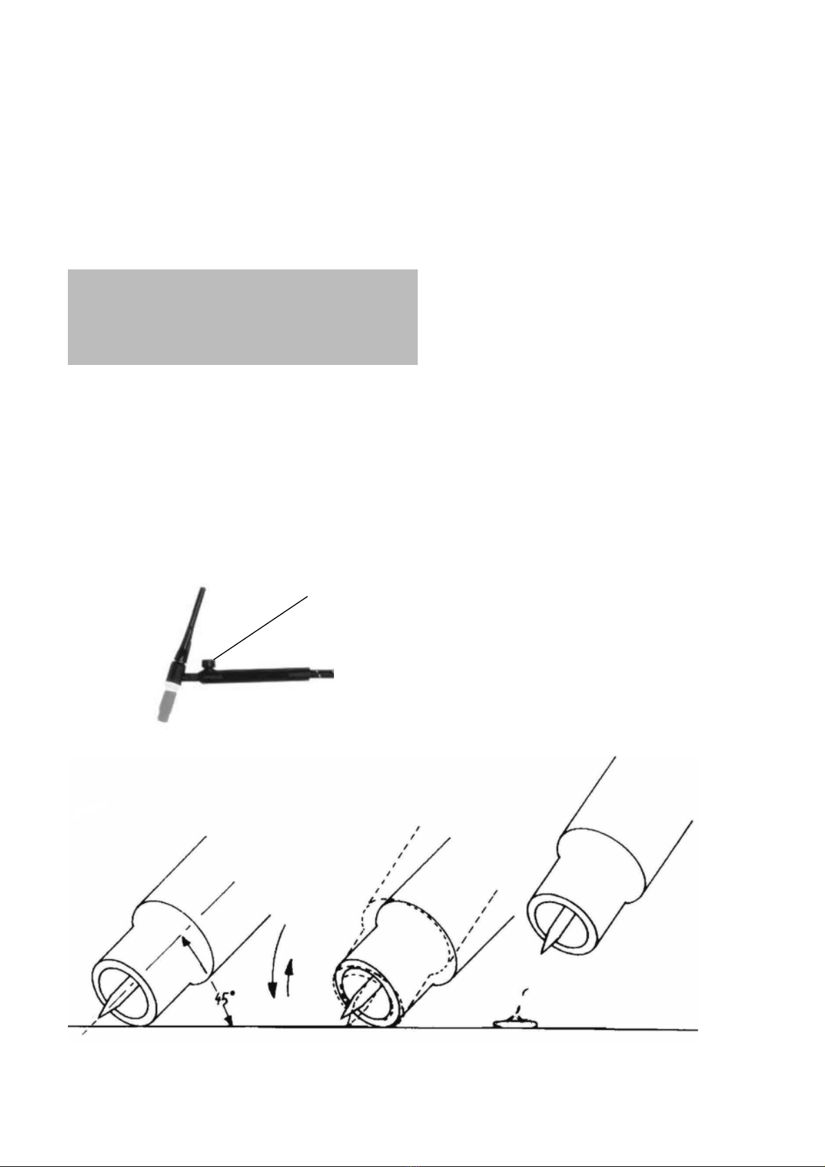
9.0 TIG WELDING BY SCRATCH ARC
- Ensure the electrode at the torch nozzle,
protrudes by 4 - 5mm., also ensure that the
electrode is sharply pointed with an angle of
40°-60°.
- Set the welding current considering the
thickness of the material to be welded and of
the diameter of the tungsten electrode to be
used.
- Open the gas valve on the torch handle,
allowing gas to flow from the torch nozzle.
Cover your face with the head shield, bring
the torch to within 3-4mm of the work, and
at an angle of 45 °, so that the ceramic noz-
zle gently touches the work surface. (fig.b).
Scratch the tip of the electrode until an arc
develops, quickly withdraw the electrode and
maintaning a gap of approx. 3-4 mm proceed
to weld. To stop welding, simply remove the
torch from the work piece.
REMEMBER to turn OFF the gas immediate-
ly you finish welding.

10
In order to avoid damages to the ge-
nerator, we suggest only expert pe-
ople to proceed with the SCRATCH
ARC welding.
NOTES:
a) The arc length generally varies between
3 and 6mm. depending on the type of joint,
type and thickness of material, and so on.
b) The torch is advanced in the direction of
welding, without lateral movement, maintai-
ning the torch angle of 45° to the workpiece.
FIG.B
FIG.A Gas valve
10.0 ORDINARY MAINTENANCE
CAUTION!!!
BEFORE CARRY OUT ANY MAINTENAN-
CE, UNPLUG THE MACHINE FROM THE
MAINS POWER SUPPLY.
The efficiency of the welding system over
time is directly related to the frequency of
maintenance jobs, such as:
For welding machines only need to be taken
care inside. The dustier the working environ-
ment is, the more often this should be done.
- Take off the lid.
- Remove all traces of dust in the inner
parts of the generator with a jet of compres-
sed air at a pressure under 3Kg/cm.
- Check all electrical connections, making
sure that nuts and screws have been firmly
tightened.
- Do not delay in replacing worn-out parts.
- Put the lid back on.
- After completing the above operations,
the generator is ready to be restarted fol-
lowing the instructions given in this manual.

11
11.0 POSSIBLE WELDING DEFECTS
DEFECT CAUSES SUGGESTIONS
POROSITY Acid electrode on steel with high
sulphur content.
Electrode oscillates too much.
Workpieces are too far apart.
Workpiece being welded is cold.
Use basic electrodes.
Move edges to be welded closer
together.
Move slowly at the beginning.
Lower welding current.
CRACKS Material to be welded is dirty (e.g.
oil, paints, rust, oxides).
Not enough current.
Cleaning workpieces before
welding is an essetial method of
achieving neat weld beads.
LIMITED
PENETRATION
Low current.
High welding rate.
Reversed polarity.
Electrode inclined in position
opposite to its movement.
Make sure operating parameters
are regulated and improve prepa-
ration of workpieces.
HIGH SPRAYS Electrode is too inclined. Make appropriate corrections.
PROFILE DEFECTS Welding parameters are incorrect.
Pass rate is not related to opera-
ting parameters requirements.
Follow basic and general welding
principles.
ARC INSTABILITY Not enough current. Check condition of electrode and
earth wire connection.
ELECTRODE MELTS
OBLIQUELY
Electrode core is not centered.
Magnetic blow phenomenon.
Replace electrode.
Connect two earth wires to opposi-
te sides of the workpiece.
INCONVENIENCE CAUSE REMEDY
SPARK WILL NOT
START
Bad primary connection.
Inverter PCB is defective.
Check primary connection.
Contact after sales service centre.
NO OUTPUT VOL-
TAGE
Overheated unit, yellow LED lit
Overvoltage protection interven-
tion, green LED off.
Overcurrent protection interven-
tion, yellow LED lit.
Internal relay has failed.
Inverter PCB is defective.
Wait for thermal cutout to be reset.
Check power line. Reset the unit
by turning it off and on after 20
seconds.
Reset the unit by turning it off and
on after 20 seconds. If the unit do-
esn’t revert working contact after
sales service centre.
Contact after sales service centre.
Contact after sales service centre.
WRONG OUTPUT
CURRENT
Defective control potentiometer.
Low primary power supply
voltage.
Contact after sales service centre.
Check power line.
12.0 TROUBLE SHOOTING
12
IMPORTANTE
LEGGETE ATTENTAMENTE LE ISTRU-
ZIONI PRIMA DI INSTALLARE L’APPA-
RECCHIO E ACCERTATEVI CHE IL CON-
DUTTORE DI MESSAA TERRA GIALLO E
VERDE SIA DIRETTAMENTE COLLEGA-
TO ALLA TERRA NEL LUOGO DI SALDA-
TURA.
L’APPARECCHIO NON DEVE MAI ES-
SERE UTILIZZATO SENZA I PANNELLI,
IN QUANTO CIO’ POTREBBE ESSERE
PERICOLOSO PER L’OPERATORE E
POTREBBE CAUSARE GRAVI DANNI
ALL’ATTREZZATURA .
L’UNITA’ LAVORA SOLO CON UNA TEN-
SIONE DI ALIMENTAZIONE DI 230Vac-
50Hz-1Ph.
IL CAVO DI ALIMENTAZIONE HA UNA
TENSIONE ANCHE QUANDO L’INTER-
RUTTORE PRINCIPALE É SULLA POSI-
ZIONE “0”. QUINDI PRIMA DI RIPARARE
L’APPARECCHIO ASSICURATEVI CHE
LA SPINA A DUE POLI NON SIA COLLE-
GATA ALLA PRESA DI CORRENTE.
Questi generatori possono essere uti-
lizzati esclusivamente con gruppi elet-
trogeni a diesel di potenza superiore a 6
KVA a 220V 50Hz.1.0 (eccetto unità ali-
mentate a 110V)
INTRODUZIONE
1.1 TIPO DI GENERATORE DI
SALDATURA
Il dati identificativi del generatore e il suo nu-
mero di serie compaiono sempre sulla targa
dati sul pannello posteriore. Le torce e i cavi
sono identificati dalle specifiche o dal numero
di serie stampati sul loro imballo. Prendete nota
di questi numeri per un eventuale riferimento.
1.2 RICEVIMENTO DELLA SORGENTE
DI SALDATURA
Quando ricevete l’apparecchiatura confron-
tatela con la fattura per assicurarvi che ci sia
corrispondenza e controllatela bene al fine di
individuare possibili danni dovuti al trasporto.
Tutte le apparecchiature spedite sono state
sottoposte ad un rigoroso controllo di quali-
tà. Se tuttavia la Vostra apparecchiatuta non
dovesse funzionare correttamente, consul-
tate la sezione RICERCA GUASTI di questo
manuale. Se il difetto permane, consultate il
Vostro concessionario autorizzato.
2.0 PRECAUZIONI SULLA SICUREZZA
2.1 ISTRUZIONI GENERALI
Questo manuale contiene tutte le istruzioni
necessarie per :
- l’installazione della sorgente di saldatura;
- un corretto utilizzo;
- un’adeguata manutenzione.
Assicuratevi che questo manuale venga letto
e capito sia dall’operatore che dal personale
tecnico addetto alla manutenzione.
2.2 LUOGO DI UTILIZZO
Se le norme di sicurezza e di utilizzo non
vengono osservate attentamente, le opera-
zioni di saldatura possono risultare perico-
lose non solo per l’operatore, ma anche per
le persone che si trovano nelle vicinanze del
luogo di saldatura.
Percio’ il proprietario e l’utilizzatore devono
essere a conoscenza di tutti i rischi possibili,
in modo tale da poter prendere le precauzioni
necessarie per evitare incidenti sul lavoro.
Le precauzioni principali da osservare sono:
- Gli operatori devono proteggere il proprio
corpo indossando tute
di protezione chiuse e
non infiammabili, sen-
za tasche o risvolti.
Eventuali tracce di olio
o grasso devono es-
sere rimosse da tutti
gli indumenti prima di
indossarli. Gli opera-
tori devono anche cal-
zare stivali con punta-
le di acciaio e suole di
gomma ( Fig. 1).
1. Guanti in pelle
2. Grembiule in pelle
3. Copriscarpe
4. Scarpe di
sicurezza
5. Mashera
- Gli operatori devono indossare un casco
o una maschera per saldatore, non infiam-
mabile, disegnato in modo da proteggere il
collo e il viso, anche dai lati. L’elmetto o la

13
- Indossate sempre occhiali di protezione
con lenti trasparenti per evitare schegge ed
altre particelle estranee che possono dan-
neggiare gli occhi (Fig.5).
- L’area di saldatura deve essere fornita di
un’ adeguata aspirazione locale che può es-
sere data da una cappa di aspirazione o da
un sistema precostruito sul banco di lavoro
che provveda all’aspirazione dai lati, davanti
e sotto, ma non sopra al banco così da evi-
tare il formarsi di polvere e fumi. L’apirazione
locale deve essere abbinata ad una adegua-
ta ventilazione generale ed al ricircolo d’aria
specialmente quando si sta lavorando un uno
spazio ristretto (Fig.6). Qualsiasi sintomo di
fastidio o dolore agli occhi, al naso o alla gola
può essere causato da una inadeguata ven-
tilazione; in tal caso interrompete immedia-
tamente il lavoro e provvedete all’adeguata
maschera devono essere dotati di vetri pro-
tettivi scuri adatti al processo di saldatura e
alla corrente usata. Occorre mantenere sem-
pre puliti i vetri di protezione e sostituirli se
sono rotti o crepati (Fig.2). E’ buona abitudi-
ne installare un vetro trasparente tra il vetro
inattinico e l’area di saldatura. Questo vetro
deve essere sostituito con frequenza quan-
do spruzzi e schegge riducono notevolmente
la visibilità. Utilizzate un respiratore quando
lavorate con piastre rivestite, che emettono
fumi tossici se riscaldate.
- L’operazione di saldatura deve essere
eseguita in un ambiente isolato rispetto alle
altre zone di lavoro, così da proteggere gli
operatori contro radiazioni e fumi. Se ciò non
è possibile, l’area di saldatura deve essere
delimitata con pannelli di protezione color
nero larghi abbastanza da restringere il cam-
po visivo delle persone nelle vicinanze della
zona (Fig.3).
- Prima di saldare allontanate dal luogo di
lavoro tutti i solventi che contengono cloro.
Alcuni solventi clorinati si decompongono
una volta esposti a radiazioni ultraviolette,
formando così gas fosgene.
- Non guardate mai, per nessun motivo, un
arco voltaico senza una adatta protezione
agli occhi ( Fig.4 ).
14
dell’area di saldatura e il cavo di massa deve
essere fissato al pezzo in lavorazione. Non
operate in una zona umida o bagnata in que-
ste condizioni (Fig.7);
- non utilizzate cavi di alimentazione o di
saldatura danneggiati (Fig.8);
- l’operatore non deve mai toccare, con
nessuna parte del corpo, pezzi di metallo ri-
scaldati ad alta temperatura o carichi elettri-
camente (Fig.9);
- l’operatore non deve mai avvolgere i cavi
di saldatura attorno al proprio corpo;
- la torcia di saldatura non deve mai essere
puntata verso l’operatore o un’altra persona.
L’apparecchio ha una protezione in classe IP
22, quindi impedisce:
- ogni contatto manuale con parti inter-
ne calde o in movimento;
- l’inserimento di corpi solidi con un dia-
metro superiore a 12mm;
- una protezione contro le cadute verti-
cali di acqua (condensazione) con inclinazio-
ne massima di 15°.
Il generatore non deve mai essere utilizzato
senza i suoi pannelli; ciò potrebbe causare
gravi lesioni all’operatore oltre a danni alla
apparecchiatura stessa.
2.4 PREVENZIONE DI INCENDIO
L’ area di lavoro deve essere conforme alle
norme di sicurezza, quindi occorre siano pre-
senti gli estintori. Mentre il soffitto, il pavimen-
to e le pareti devono essere non infiammabili.
Tutto il materiale combustibile deve essere
spostato dal luogo di lavoro (Fig.10). Se non
si può allontanare il combustibile, copritelo
con una copertura resistente al fuoco. Prima
di cominciare a saldare, ventilate gli ambien-
ventilazione dell’area.
- Il procedimento di saldatura deve esse-
re eseguito su superfici metalliche ripulite
da strati di ruggine o vernice e ciò al fine di
evitare il formarsi di fumi dannosi. Prima di
saldare occorre asciugare le parti che sono
state sgrassate con solventi.
-Non saldate metalli o metalli verniciati che
contengono zinco, piombo, cadmio o berillio
a meno che l’operatore e le persone vicine
non indossino un respiratore o un elmetto
con bombola di ossigeno.
- La protezione tecnica e sanitaria di tutti gli
operatori addetti alla saldatura - coinvolti sia
direttamente che indirettamente nel processo
- è garantita anche dalle disposizioni di legge
e ciò al fine di evitare gli incidenti sul lavoro.
2.3 ISTRUZIONI PER LA SICUREZZA
Per salvaguardare la vostra sicurezza, se-
guite attentamente queste istruzioni prima di
collegare il generatore alla linea:
- un interruttore adeguato a due poli deve es-
sere inserito prima della presa principale di
corrente; questa deve essere dotata di fusibili
ritardati che devono essere conformi ai valori
indicati nel capitolo “Dati Tecnici”;
- il collegamento mono-fase con cavo di
terra deve essere eseguito con una spina a
due poli compatibile con la presa menzionata
sopra;
- i due fili del cavo di alimentazione a due
poli sono impiegati per il collegamento con la
linea mono-fase mentre il filo giallo-verde è
usato per il collegamento obbligatorio a terra
nel luogo di saldatura;
- collegate al terminale di terra tutte le parti
metalliche che sono vicine all’operatore, uti-
lizzando cavi più grossi o della stessa sezio-
ne dei cavi di saldatura;
- quando state lavorando in un luogo ristret-
to, l’apparecchio deve essere collocato fuori

15
ti dove l’area è potenzialmente infiammabi-
le. Non operate in un’atmosfera che ha una
concentrazione notevole di polvere, gas in-
fiammabile o vapore liquido combustibile. Il
generatore deve essere situato in un luogo
con pavimento solido e liscio; non deve esse-
re appoggiato al muro. Non saldate recipienti
che contenevano benzina, lubrificante o al-
tre sostanze infiammabili. Dopo aver finito di
saldare, accertatevi sempre che nella zona
non siano rimasti materiali incandescenti o in
fiamme.
2.5 GAS DI PROTEZIONE
Per il processo di saldatura utilizzate il gas
corretto. Assicuratevi che il regolatore instal-
lato sulla bombola funzioni correttamente.
Ricordate di conservare la bombola lontano
da fonti di calore.
2.6 LIVELLO DI RUMORE PERMESSO
DALLA LEGGE 86/188/EEC
Operando in condizioni normali, l’apparecchiatu-
ra utilizzata per la saldatura ad arco non supera
gli 80 dBA. Comunque in condizioni particolari,
ad esempio alti parametri di saldatura in ambien-
ti limitati, i livelli del rumore possono eccedere il
limite permesso. Per questa ragione è fortemen-
te raccomandato di indossare idonee protezioni
per le orecchie.
2.7 COMPATIBILITÀ
ELETTROMAGNETICA
Prima di installare una unità di saldatura
STICK/TIG, effettuate una ispezione dell’area
circostante, osservando quanto segue:
1- Accertatevi che vicino all’ unità non vi sia-
no altri cavi di generatori, linee di controllo,
cavi telefonici o apparecchiature varie.
2- Controllate che non siano presenti ricevitori
telefonici o apparecchiature televisive.
3- Assicuratevi che non vi siano computer o
altri sistemi di controllo.
4- Nell’area attorno alla macchina non
devono essere presenti persone con pa-
cemaker o protesi per l’udito.
5- Controllate l’immunità di ogni strumento
che opera nello stesso ambiente.
In casi particolari possono essere richieste
misure di protezione aggiuntive.
Le interferenze possono venire ridotte se-
guendo questi accorgimenti:
1- Se c’è una interferenza nella linea del ge-
neratore, si può inserire un filtro E.M.C tra la
rete e l’unità.
2- I cavi di uscita della macchina dovrebbero
essere accorciati, tenuti assieme e allungati
a terra.
3- Dopo aver terminato la manutenzione,
occorre chiudere in maniera corretta tutti i
pannelli del generatore.
2.8 CURE MEDICHE E DI PRIMO
SOCCORSO
Ogni luogo di lavoro deve essere dotato di
una cassetta di pronto soccorso e deve esse-
re presente una persona qualificata in cure di
primo soccorso, per un aiuto immediato alle
persone vittime di uno shock elettrico. Inoltre
devono essere disponibili tutti i trattamenti
per la cura di bruciature degli occhi e della
pelle.
CURE DI PRIMO SOCCORSO:
Chiamate subito un medico e una ambu-
lanza. Ricorrete a pratiche di Primo Soc-
corso raccomandate dalla Croce Rossa.
ATTENZIONE: LO SHOCK ELETTRICO
PUO’ ESSERE MORTALE
Se la persona è incosciente e c’è il so-
spetto di uno shock elettrico, non tocca-
te la persona se lei o lui sono in contatto
con comandi. Togliete l’alimentazione alla
macchina e ricorrete a pratiche di Primo
Soccorso. Per allontanare i cavi dalla vit-
tima puo’ essere usato, se necessario, le-
gno asciutto o una scopa di legno o altro
materiale isolante.

16
3.0 CARATTERISTICHE GENERALI
La vostra saldatrice fa parte di una serie
composta da inverter per saldatura a elettro-
do (MMA - Manual Metal Arc Welding) che
adottano la tecnologia della modulazione
della larghezza degli impulsi (PWM - Pulse
Width Modulation) e moduli di potenza con
transistor bipolare con gate isolato (IGBT
- Insulated Gate Bipolar Transistor) per ga-
rantire ottime prestazioni: corrente costante
in uscita per rendere l’arco di saldatura più
stabile e regolazione lineare della corrente.
Tutti gli inverter sono dotati di alcune funzio-
ni di protezione automatiche: sovratensione,
sovracorrente, sovratemperatura.
3.1 DATI TECNICI
NOTA: i dati qui riportati possono differire
da quelli riportati in targa dati sulla mac-
china. Fate sempre riferimento anche alla
targa dati della macchina.
4.0 INSTALLAZIONE
DELL’APPARECCHIATURA
Il buon funzionamento del generatore è
assicurato da una sua adeguata instal-
lazione che deve quindi essere eseguita
da personale esperto, seguendo le istru-
zioni e nel pieno rispetto delle norme
anti-infortunio.
- Togliete la saldatrice dal cartone.
Prima di effettuare qualsiasi collegamen-
to elettrico controllate la targa dati tecnici
ed accertatevi che la tensione in entrata
e la frequenza siano gli stessi della rete
principale che deve essere usata.
MESSA A TERRA
- Per la protezione degli utenti la salda-
trice dovrà essere assolutamente colle-
gata correttamente all’impianto di terra
(NORMATIVE INTERNAZIONALI DI SICU-
REZZA)
- E’ indispensabile predisporre una
buona messa a terra tramite il condutto-
re giallo-verde del cavo di alimentazione,
onde evitare scariche dovute a contatti
accidentali con oggetti messi a terra.
- Lo chassis, che è conduttivo, è con-
nesso elettricamente con il conduttore
di terra; non collegare correttamente a
terra l’apparecchiatura può provocare
shock elettrici pericolosi per l’utente.
- Collegate l’inverter alla rete.
Non utilizzate l’inverter con prolunghe di
cavi di alimentazione che superino i 10m
o con sezione inferiore a 2.5mm². Ricor-
datevi di tenere i cavi ben distesi e non
avvolti o ingarbugliati.
Non usate l’inverter con i pannelli par-
zialmente o completamente rimossi al
fine di evitare il contatto accidentale con
le parti più interne che sono cariche.
- L’inverter è adesso pronto per l’utilizzo. Ac-
certatevi di saldare in un’area adeguatamente
ventilata e che le prese per l’aria della macchi-
na non siano ostruite (una scarsa ventilazione
potrebbe ridurre il rendimento della macchina
e causare danni). Ora potete scegliere il pro-
cesso di saldatura collegando gli accessori
come indicato nelle pagine seguenti.
100 Amps 130 Amps
- A 130 Amps
- B
(1 ph)
230V
50/60Hz 230V
50/60Hz 230V
50/60Hz
Power 60% KVA
2,4 2,7 2,7
Uo V
60 60 60
Amp.Min-Max A±10%
5 ÷ 100 5 ÷ 130 5 ÷ 130
Amp. 60974-1 A
15% 100
60% 50 15% 130
60% 65 20% 130
60% 75
ØEmm
1,6 ÷ 2,5 1,6 ÷ 3,25 1,6 ÷ 3,25
Insulation -
HHH
Protec. Degree -
IP22 IP22 IP22
160 Amps 160 Amps DV
(1 ph)
230V
50/60HZ 115V 230V
Power 60% KVA
4,2 3,8 4,2
Uo V
65 65 65
Amp.Min-Max A±10%
5 ÷ 160 5 ÷ 140 5 ÷ 160
Amp.
60974-1 A
30% 160
60% 115 35% 140
60% 105 30% 160
60% 115
ØEmm
1,6 ÷ 4 1,6 ÷ 3,25 1,6 ÷ 4
Insulation -
HH
Protec. Degree -
IP22 IP22
200 Amps
(1 ph)
230V 50/60Hz
Power 60% KVA
6
Uo V
65
Amp.Min-Max A±10%
5 ÷ 200
Amp. 60974-1 A
25% 200 60% 160
ØEmm
1,6 ÷ 5
Insulation -
H
Protec. Degree -
IP22

17
5.0 FUNZIONI E CONNESIONI
DELL’INVERTER
1 Potenziometro regolazione corrente di
saldatura
2 Interruttore Stick / Tig (solo per alcuni
modelli)
3 Led verde di rete
Led ON =generatore acceso
Led OFF = generatore spento
Intervento Protezione sovratensione (ripri-
stinate l’unità spegnendola, aspettate 20 se-
condi, poi riaccendetela)
4 Led giallo
Led ON = allarme per sovratemperatura.
Attenzione: Lasciate che l’unità si raffreddi,
quando pronta il led si spegnerà automatica-
mente.
Led ON = sovracorrente. Provate a spegnere
e riaccendere la macchina. Nel caso la prote-
zione sia interventuta per un picco di corren-
te la macchina riprenderà a funzionare, nel
caso che la macchina non riprenda il suo nor-
male funzionamento rivolgetevi ad un centro
assistenza.
5 presa dinse positiva
6 presa dinse negativa
7 Cavo di alimentazione (retro)
8 Interruttore ON/OFF (retro)
6.0 SALDATURA AD ARCO
Norme generali
L’arco elettrico può essere descritto come
una fonte di luce brillante e di calore in-
tenso. Infatti il flusso di corrente elettrica
nell’atmosfera del gas che circonda l’elet-
trodo e il pezzo da saldare provocano
l’emanazione di onde elettromagnetiche
che vengono percepite come una luce o
una fonte di calore, a seconda della lun-
ghezza d’onda. Ad un livello impercettibile,
l’arco produce anche luce ultra-violetta e
infra-rossa; i raggi ionizzati non vengono
mai percepiti. Il calore prodotto dall’arco
è utilizzato nel processo di saldatura per
fondere e unire assieme parti di metallo.
La corrente elettrica necessaria è fornita da
una apparecchiatura comunemente chia-
mata saldatrice.
- Collegate il cavo di massa al polo negati-
vo dell’inverter e la pinza di massa al pezzo
di saldatura.
- Collegate il cavo di saldatura al polo posi-
tivo dell’inverter.
- Selezionate la corrente di saldatura utiliz-
zando la manopola di controllo sul pannello
frontale. La corrente di saldatura deve essere
scelta seguendo le istruzioni fornite dal pro-
duttore degli elettrodi e scritte sulla confezio-
ne degli stessi.
Le indicazioni seguenti possono essere utili
come informazioni generali:
- Accendete l’inverter. I due leds sul pan-
nello saranno rispettivamente:
quello verde = acceso, quello giallo = spento
ODORTTELE'LLEDORTEMAIDARUTADLASIDETNERROC
mm5.1A04-A03
mm0.2A56-A05
mm5.2A001-A07
mm52.3A041-A001
mm0.4A061-A041
1
2
5
6
34
8
7

18
(per maggiori dettagli fate riferimento alla pa-
gina precedente). Nei modelli che consento-
no la saldatura ad elettrodo e Tig selezionare
la saldatura ad arco mediante interruttore po-
sto sul pannello frontale.
- Proteggete la vostra faccia con una ma-
schera o con un elmetto. Toccate con l’elet-
trodo inserito nella pinza portaelettrodo il pez-
zo da saldare, fino a che l’arco non si innesca
(l’inverter ha la funzione “HOT START” per
migliorare l’innesco).
Evitate di danneggiare il pezzo da saldare
con l’elettrodo, perche’ potrebbe liberare
il rivestimento e aumentare le difficolta’ di
innesco dell’arco.
- Dopo l’innesco dell’arco mantenete l’elet-
trodo nella stessa posizione con un angolo
di circa 60° e muovendo da sinistra a destra
potrete controllare visivamente la saldatura.
La lunghezza dell’arco puo’ essere control-
lata anche alzando o abbassando legger-
mente l’elettrodo. Una variazione dell’angolo
di saldatura potrebbe aumentare la misura
dell’area di saldatura, migliorando la capaci-
ta’ di copertura della scoria.
- Alla fine della saldatura lasciate raffred-
dare il residuo prima di toglierlo, usando la
spazzola con il puntale.
Attenzione:
-proteggete i vostri occhi
-evitate danni quando togliete il residuo
con la spazzola ed il puntale.
ATTENZIONE!
Un cattiva partenza puo’ essere provocata
dal materiale da saldare sporco, da un cat-
tivo collegamento tra il cavo di massa ed
il pezzo da saldare o da errato fissaggio
dell’elettrodo nella pinza porta elettrodo.
7.0 QUALITA’ DELLA SALDATURA
La qualità della saldatura dipende principal-
mente dall’ abilità del saldatore, dal tipo di
saldatura e dalla qualità dell’ elettrodo. Prima
di cominciare a saldare scegliete il modello e
il diametro dell’ elettrodo più adatti, prestan-
do attenzione allo spessore e alla composi-
zione del metallo da saldare e alla posizione
della saldatura.
Corrente corretta di saldatura.
Se l’intensità di corrente è troppo alta, l’elet-
trodo si brucierà in fretta, mentre la saldatura
risulterà molto irregolare e difficile da control-
lare. Se la corrente è invece troppo bassa,
perderete potenza e la saldatura risulterà
stretta e irregolare.
Lunghezza corretta dell’arco.
Se l’arco è troppo lungo, esso causerà sba-
vature e una piccola fusione del pezzo in
lavorazione. Se invece l’arco è troppo corto
il suo calore risulterà insufficiente e di con-
seguenza l’elettrodo si attaccherà al pezzo in
lavorazione.
Velocità corretta di saldatura.
La corretta velocità di saldatura consentirà
di ottenere una saldatura dall’ ampiezza più
adatta, senza onde o scanalature.
8.0 SALDATURA A TIG
Il processo a tig utilizza l’arco elettrico inne-
scato tra l’elettrodo a tungsteno della torcia e
la superficie del pezzo da saldare.
Nella saldatura a tig la torcia è sempre col-
legata al polo negativo della saldatrice.
Preparazione della saldatrice :
- selezionate la saldatura a TIG
- Collegate il cavo di massa al polo positivo
della saldatrice e la pinza di massa al pezzo
da saldare.
- Collegate la torcia tig al polo negativo del-
la saldatrice e il tubo del gas al regolatore di
pressione della bombola di gas.
Il flusso del gas è controllato manualmen-
te tramite la manopola sull’impugnatura
della torcia. Utilizzate solo gas inerte (Ar-
gon).
- Accendete l’inverter.
9.0 SALDATURA A TIG CON
PARTENZA A STRISCIO
- Assicuratevi che l’elettrodo sporga
dall’ugello almeno 4-5mm, assicuratevi an-
che che la sua punta sia a circa 40°-60° dal
pezzo.
- Impostate la corrente di saldatura consi-
derando lo spessore del materiale da salda-
re ed il diametro dell’elettrodo tungsteno da
usare.
- Aprite la valvola del gas sull’impugna-
tura della torcia, lasciando fuoriuscire il gas
dall’ugello. Coprite la vostra faccia con la
19
maschera di protezione, portate la torcia
a 3-4mm dal pezzo e ad un angolo di cir-
ca 45°, in modo che l’ugello cermico tocchi
la superficie del pezzo (fig.b). Sfregate la
punta dell’elettrodo finchè l’arco si sviluppa,
allontanatevi subito e mantenete una distan-
za di circa 3-4mm procedendo a saldare. Per
terminare la saldatura sollevate la torcia dal
pezzo da saldare.
RICORDATEVI di chiudere la valvola del gas
quando avete terminato di saldare.
Per evitare di compromettere il buon fun-
zionamento del generatore, si consiglia
di far utilizzare la partenza in Scratch Arc
solo a personale esperto.
NOTA:
a) La lunghezza dell’arco varia generalemen-
te da 3 a 6mm a seconda del tipo di giunto,
tipo e spessore di materiale, ecc..
b) La torcia deve avanzare nella direzione
della saldatura, senza movimenti laterali,
mantenendo un angolo di 45° con il pezzo da
saldare.
10.0 MANUTENZIONE ORDINARIA
ATTENZIONE!!!
PRIMA DI OGNI INTERVENTO SCONNE-
TERE LA MACCHINA DALLA RETE PRI-
MARIA DI ALIMENTAZIONE.
L’efficienza dell’impianto di saldatura nel tem-
po, è direttamente legata alla frequenza delle
operazioni di manutenzione, in particolare:
Per le saldatrici è sufficiente avere cura della
loro pulizia interna, che va eseguita tanto più
spesso, quanto più polveroso è l’ambiente di
lavoro.
- Togliete la copertura.
- Togliete ogni traccia di polvere dalle parti
interne del generatore mediante getto d’aria
compressa con pressione non superiore a 3
KG/cm.
- Controllate tutte le connessioni elettriche, as-
sicurandovi che viti e dadi siano ben serrati.
- Non esitate nel sostitiuire i componenti
deteriorati.
- Rimontare la copertura.
- Esaurite le operazioni sopra citate, il ge-
neratore è pronto per rientrare in servizio se-
guendo le istruzioni riportate in questo ma-
nuale.
FIG.A Valvola gas
FIG.B FIG.C FIG.D

20
11.0 POSSIBILI DIFETTI DI SALDATURA
12.0 POSSIBILI INCONVENIENTI DI FUNZIONAMENTO
INCOVENIENTE CAUSA RIMEDIO
MANCATA
ACCENSIONE
Allacciamento primario non
corretto.
Scheda inverter difettosa.
Controllare il collagamento pri-
mario.
Rivolgersi al proprio centro di
assistenza.
ASSENZA DI TEN-
SIONE IN USCITA
Macchina surriscaldata, Led giallo
acceso.
Limiti di sovratensione superati,
Led verde spento.
Intervento protezione per sovra-
corrente, Led giallo acceso
Relè interno guasto.
Scheda inverter difettosa.
Aspettare il ripristino termico.
Controllare la rete di distribuzione.
Ripristinare l’unità spegnendola,
aspettare 20 secondi, poi riaccen-
derla.
Ripristinare l’unità spegnendo-
la, aspettare 20 secondi, poi
riaccenderla. In caso di mancato
funzionamento rivolgersi al proprio
centro di assistenza.
Rivolgersi al proprio centro di
assistenza.
CORRENTE IN
USCITA NON
CORRETTA
Potenziometro di regolazione
difettoso.
Tensione di alimentazione prima-
ria bassa.
Rivolgersi al proprio centro di
assistenza.
Controllare la rete di distribuzione.
DIFETTO CAUSE CONSIGLI
POROSITA’ Elettrodo acido su acciao ad alto
tenore di zolfo.
Oscillazioni eccessive dell’elet-
trodo.
Distanza eccessiva tra i pezzi da
saldare.
Pezzo in saldatura freddo.
Usare elettrodo basico.
Avvicinare i lembi da saldare.
Avanzare lentamente all’inizio.
Diminuire la corrente di saldatura.
CRICCHE Materiale da saldare sporco (es.
olio, vernice, ruggine, ossidi).
Corrente insufficiente.
Pulire il pezzo prima di saldare è
principio fondamentale per ottene-
re buoni cordoni di saldatura.
SCARSA
PENETRAZIONE
Corrente bassa.
Velocità di saldatura elevata.
Polarità invertita.
Elettrodo inclinato in posizione
opposta al suo movimento.
Curare la regolazione dei parame-
tri operativi e migliorare la prepara-
zione del pezzo da saldare.
SPRUZZI ELEVATI Inclinazione eccessiva dell’elet-
trodo.
Effettuare le opportune correzioni.
DIFETTI DI PROFILI Parametri di saldatura non
corretti.
Velocità passata non legata alle
esigenze dei parametri operativi.
Rispettare i principi basilari e
generali di saldatura.
INSTABILITA’
DELL’ARCO
Corrente insufficiente. Controllare lo stato dell’elettrodo ed
il collegamento del cavo di massa.
FUSIONE OBLIQUA
DELL’ELETTRODO
Elettrodo con anima non centrata.
Fenomeno del soffio magnetico.
Sostituire l’elettrodo.
Connettere due cavi di massa ai
lati opposti del pezzo da saldare.
Table of contents
Languages:
Other Helvi Welding System manuals

Helvi
Helvi TIGMAKER 210HF PULSE User manual

Helvi
Helvi SPOT 5000 User manual

Helvi
Helvi PANTHER 152 User manual

Helvi
Helvi GLOBUS 175HF User manual

Helvi
Helvi PC EVO 50.1 User manual

Helvi
Helvi PC AUTO User manual

Helvi
Helvi PUMA 256 User manual

Helvi
Helvi GLOBUS 201 User manual

Helvi
Helvi PUMA 298 User manual

Helvi
Helvi TP 195 User manual

Helvi
Helvi GALILEO 179 User manual

Helvi
Helvi SPOTCAR EVO 4000 User manual

Helvi
Helvi GLOBUS 260HF User manual

Helvi
Helvi Maximig 358 User manual

Helvi
Helvi FOX 211 User manual

Helvi
Helvi MULTITECH 365 User manual

Helvi
Helvi COMPACT 360AC/DC User manual

Helvi
Helvi PC75 User manual

Helvi
Helvi COMPACT 400 User manual

Helvi
Helvi COMPACT 211 EASY AC/DC User manual


