Hengstler Signo 721 User manual

Komponenten 2000140 DREHGEBER ZÄHLER REGLER ANZEIGER RELAIS DRUCKER ABSCHNEIDER
signo 721 Kompakter Vorwahlzähler
■1 oder 2 Vorwahlen
■Prescaler mit Ausgang zum Anschluss eines Summenzählers
■Große, 5stellige LED-Anzeige
■Anschluss über steckbare Schraubverbindungen
■Vielfältig programmierbar
■Kleine, kompakte Bauform im DIN-Maß 48 x 48 mm
■Tastatur gegen unbefugte Eingaben verriegelbar
■Elektronische Werterhaltung, umweltfreundlich ohne Batterien
ANZEIGE 5stellige LED-Anzeige mit 7 mm hohen Ziffern. Sie ist bequem ablesbar, ein Dezi-
malpunkt (Komma) ist bei Bedarf programmierbar.
Zeile 1: Zeigt im Zählbetrieb den aktuellen Zählerstand und im Programmierbetrieb
die Eingabewerte an.
Zeile 2: Zeigt dem Bediener im Programmierbetrieb die einzelnen Program-
mierschritte an.
Zähler mit einer Vorwahl
P
Vorwahl
COR
Korrektur
PSC
Prescaler
Werteingabe
WERTEINGABE
Über die 4 großen Tasten an der Front-
seite des Zählers können die in der Abb.
gezeigten Werte eingegeben oder verän-
dert werden.
P1
Vorwahl 1
P2
Vorwahl 2
COR
Korrektur
PSC
Prescaler
Werteingabe
Zähler mit zwei Vorwahlen
Zähler mit Tor und Anzeigespeicher Zähler mit up/down
Reset
Auto-Reset On
see Key 1 Off
Key 2 Off
Key-Reset Lock
Input 5kHz
Display-Hold Off
Inhibit Off
pnp-Input
0,05s
1s
bist.
Out
9 8 7 6 5 4 3 2 1
Set
Off
On
On
On
30Hz
On
On
npn
Reset
Auto-Reset On
see Key 1 Off
Key 2 Off
Key-Reset Lock
Input 5kHz
pnp-Input
0,05s
1s
bist.
Out
Set
Off
On
On
On
30Hz
npn
9 8 7 6 5 4 3 2 1
Tastatur-
sperre
S. 91
Tastatur-
sperre
S. 91
PROGRAMMIERUNG
Durch die im Bild dargestellte Schalterstellung ist der Zähler wie folgt programmiert:
9 – Set-Mode (subtrahierende Zählweise)
8 – Mit automatischer Wiederholung
7 – Vorwahlen, Korrekturwert und
6 – Prescaler sind bei nicht angesteuertem „Keylock“-Eingang veränderbar
5 – Tastaturreset ist aktiv
4 – Zählfrequenz max. 5 kHz
3 – Anzeigespeicher Aus Bei u/d Schalter
2 – Tor auf Appl. Eingang ohne Funktion
1 – pnp Eingangslogik
Poti – Signaldauer OUT ca. 1 sek.
}

141Komponenten 2000 DREHGEBER ZÄHLER REGLER ANZEIGER RELAIS DRUCKER ABSCHNEIDER
Anzeige 5 stellig, LED
Ziffernhöhe 7 mm
Versorgungsspannung Ub: 12 … 24 V DC –5 +10 % oder 24 V AC +– 10 % oder
100 … 240 V AC, entspr. Ausführung
Stromaufnahme bei 12 … 24 V DC < 300 mA, bei 24 VAC < 255 mA,
bei 100 … 240 V AC < 55 mA
Geberversorgung AC-Betrieb 24 V DC +– 10 %, DC-Betrieb Ub– 2 V
Werterhaltung ca. 10 Jahre, NV-Speicher
Betriebstemperatur 0 … + 50 °C
Lagertemperatur – 20 … + 70 °C
Elektr. Anschluss Steckbare Schraubverbindung
Schutzart (IEC 144) Frontseite IP 54, Anschlüsse IP 20
Störfestigkeit EMV Schärfegrad 3 nach IEC 801-T2 + T4
Schwingfestigkeit 30 m/s2(50 – 500 Hz) nach IEC 068-2-6
Schockfestigkeit 100 m/s2(10 ms) nach IEC 068-2-27
Allgemeine Auslegung nach DIN VDE 0411; Isolationsgruppe C
Gewicht ca. 200 g
Zulassungen CSA: LR 30208-12-13
Eingänge
Amplitudenschwellen < 2 V und > 8 V; max. + 40 V DC
Aktive Flanke positiv, umschaltbar auf negativ
Impulsform beliebig (bei max. Frequenz Rechteck 1:1)
Eingangswiderstand ca. 22 kΩ
Zähleingang addierend oder subtrahierend porgrammierbar,
Prescaler von 0,001 … 9,999 einstellbar
Impulsdauer mind. >100 µs/>17 ms (entspr. Zählfrequenz)
Zählfrequenz max. 5 kHz/30 Hz
Steuereingänge
Impulsform PNP oder NPN umschaltbar
Rückstellung (Reset) mit statischem Verhalten
– manuell durch Taste
– elektrisch, Impulslänge >17 ms
– automatisch mit Ansprechen von OUT 2
(nur bei entspr. Programmierung)
Verriegelung (Keylock) gesamte Tastatur oder nur Vorwahl 1 (entspr. Programmierung),
statisches Verhalten, Impulslänge >17 ms
Applikationen (Appl) Tor, Up/Down oder Anzeigespeicher, entspr. Ausführung
Signal muß 50 µs vor dem Zählimpuls anstehen
Ausgänge
Signalausgänge OUT 1 und OUT 2, entspr. Ausführung
Signaldauer OUT 1: Bei Erreichen der VW 1 bis Ansprechen von OUT2
OUT 2: Bei Erreichen der VW 2 von 0,05 s … bistabil (einstellbar)
Relais
Kontaktart Zähler mit 1 VW: Wechsler Zähler mit 2 VW: Schließerkontakt
Schaltspannung max. 250 V AC oder 30 V DC
Schaltstrom max. 1 A, mind. 100 mA bei 20 V
Transistor
Schaltspannung AC-Betrieb 24 V DC, DC-Betrieb Ub–2 V
Schaltstrom 20 mA
Prescaler (PSC-OUT)
Schaltspannung AC-Betrieb 24 V DC +– 10 %, DC-Betrieb Ub–2 V
Schaltstrom 10 mA max.
Signaldauer typ. 90 µs
TECHNISCHE DATEN
Technische Daten signo 721

Komponenten 2000142 DREHGEBER ZÄHLER REGLER ANZEIGER RELAIS DRUCKER ABSCHNEIDER
signo 721 Technische Daten
Zähler mit 1 Vorwahl Zähler mit 2 Vorwahlen
Keyl 1 Keyl 2 Keylock P COR PSC Keyl 1 Keyl 2 Keylock P1 P2 COR PSC
Schalter Schalter Klemme Schalter Schalter Klemme
7 6 14 7 6 14
off off low A A A off off low A A A A
off off high A A L off off high L A A L
on off low A – A on off low A A – A
on off high L A L on off high L L A L
off on low A – L off on low A A – L
off on high A – L off on high L A – L
on on low A – L on on low A A – L
on on high L – L on on high L L – L
A = aktiv, L = gesperrt, – = ausgeblendet
TASTATURSPERRE
Maße in mm
ANSCHLUSSBILD
NC = nicht belegt
1
2
3
4
5
6
7
8
9
10
11
12
13
14
15
16
– AC-DC Spannungsversorgung
+
NC
NC
NC
OUT Relais- oder
Transistorausgang
OV Geberspannungsversorgung
+
Input
Reset
Appl.
Keylock
Prescaler-OUT
NC *
1
2
3
4
5
6
7
8
9
10
11
12
13
14
15
16
*
– AC-DC
Spannungsversorgung
+
NC
OUT1 Relais- od.
Transistorausgang
NC
OUT2 Relais- od.
Transistorausgang
OV Geberspannungsversorgung
+
Input
Reset
Appl.
Keylock
Prescaler-OUT
NC *
BESTELLANGABEN
Zähler mit 1 Vorwahl Zähler mit 2 Vorwahlen
Zähler mit: Relaisausgang Transistorausgang
Funktion Versorgung 1 Vorwahl 2 Vorwahlen 1 Vorwahl 2 Vorwahlen
Art.-Nr. Art.-Nr. Art.-Nr. Art.-Nr.
Tor/Anzsp. 12 … 24 VDC 0 721 101 0 721 105 0 721 103 0 721 107
24 VAC 0 721 109 0 721 110 ––– –––
100 … 240 VAC 0 721 102 0 721 106 0 721 104 0 721 108
Up/down 12 … 24 VDC 0 721 121 0 721 125 ––– –––
100 … 240 VAC 0 721 122 0 721 126 ––– –––
Weitere Ausführungen auf Anfrage
MASSZEICHNUNG

Components 2000140 ENCODERS COUNTERS CONTROLLERS INDICATORS RELAYS PRINTERS CUTTERS
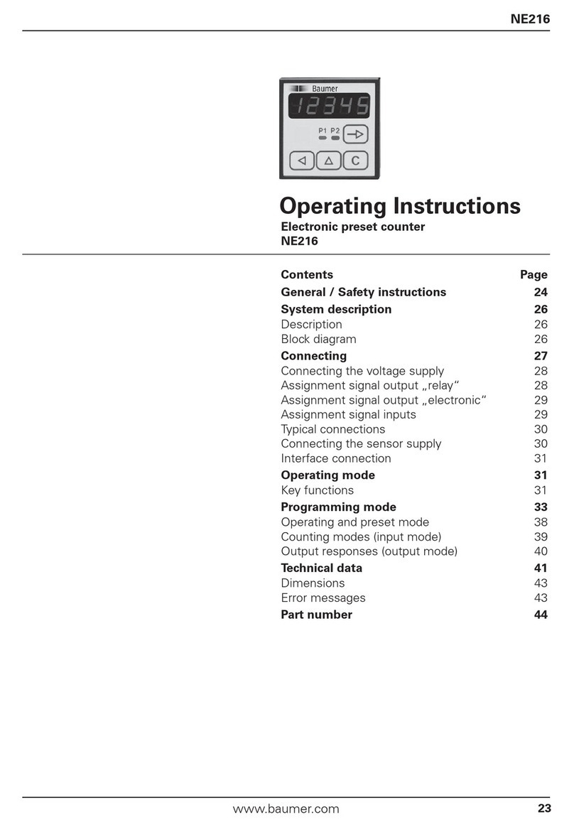
signo 721 Compact Preset Counter
■1 or 2 presets
■Prescaler with output for connection of a totalizing counter
■Large, 5-digit LED display
■Connection by plug-in screw terminals
■Variety of programming possibilities
■Small, compact design in DIN dimensions 48 x 48 mm
■Keypad can be secured against unauthorized access
■Electronic value retention, environmentally sound, uses no batteries
DISPLAY 5-digit LED display with 7 mm high digits. Easy to read, decimal point can be pro-
grammed if required.
Line 1: Shows the current count in counting operation and entry values in program-
ming mode.
Line 2: Shows the operator the individual programming steps during programming.
Counter with one preset
P
Preset
COR
Correction
Prescaler
Value input
VALUE INPUT
Values shown in the diagrams can be
entered or modified with four large keys
on the front of the counter.
P1
Preset 1
P2
Preset 2
COR
Correction
PSC
Prescaler
Value input
Counter with two presets
Counter with gate and display memory Counter with up/down
Reset
Auto-Reset On
see Key 1 Off
Key 2 Off
Key-Reset Lock
Input 5kHz
Display-Hold Off
Inhibit Off
pnp-Input
0,05s
1s
bist.
Out
9 8 7 6 5 4 3 2 1
Set
Off
On
On
On
30Hz
On
On
npn
Reset
Auto-Reset On
see Key 1 Off
Key 2 Off
Key-Reset Lock
Input 5kHz
pnp-Input
0,05s
1s
bist.
Out
Set
Off
On
On
On
30Hz
npn
9 8 7 6 5 4 3 2 1
Table
Keylock
(Page 78)
Table
Keylock
(Page 78)
PROGRAMMING
The switch positions illustrated in the diagram program the counter as follows:
9 – Set mode (subtracting count)
8 – With automatic repeat
7 – Presets, correction value and
6 – prescaler can be modified if "keylock" input is not actuated
5 – Keypad reset activated
4 – Max. counting frequency 5 kHz
3 – Display memory Off without function
2 – Gate to appl. input for u/d switch
1 – pnp input logic
Pot – Signal duration OUT approx. 1 sec.
}

141Components 2000 ENCODERS COUNTERS CONTROLLERS INDICATORS RELAYS PRINTERS CUTTERS
Display 5-digit, LED, decimal point with soldering bridge
Digit height 7 mm
Supply voltage Vop: 12 … 24 VDC – 5/+ 10 % or 24 VAC ± 10 % or
100 … 240 VAC, depending on version
Current consumption on 12 … 24 VDC < 300 mA, on 24 VAC < 255 mA,
on 100 … 240 VAC < 55 mA
Sensor supply AC operation 24 VDC +– 10 %, DC operation Vop - 2 V
Value retention approx. 10 years, NV memory
Operating temperature 0 … + 50 °C
Storage temperature – 20 … + 70 °C
Electrical connection plug-in screw terminals
Protection class (IEC 144) front IP 54; connections IP 20
Interference immunity EMC severity 3 acc. to IEC 801 - pt. 2 + pt. 4
Vibrostability 30 m/s2(50 ... 500 Hz) acc. to IEC 068-2-6
Shock stability 100 m/s2(10 ms) acc. to IEC 068-2-27
General design acc. to DIN VDE 0411; insulation group C
Weight approx. 200 g
Approvals CSA: LR 30208-12-13
Inputs
Amplitude thresholds < 2 V and > 8 V; max. + 40 VDC
Active edge positive, can be switched to negative
Pulse shape random (squarewave 1:1 for max. frequency)
Input resistance approx. 22 kΩ
Count input adding programmable, prescaler, adjustable
from 0.001...9.999
Min. pulse length > 100 µs / > 17 ms (depending on counting frequency)
Max. counting frequency 5 kHz / 30 Hz
Control inputs
Pulse shape PNP or NPN (able to switch over)
Reset with static behaviour
- manual via keypad
- electric, pulse length > 17 ms
- automatic when OUT2 responds (only if programmed
accordingly)
Keylock full keypad or only preset 1 (depending on program), static
behaviour, pulse length > 17 ms
Application (Appl.) gate, up/down or display memory, depending on version
Signal must be applied 50 µs before count pulse
Outputs
Signal outputs OUT1 and OUT2, depending on version
Signal duration
OUT1: starts when P1 is reached and ends when OUT2 responds
OUT2: starts when P2 is reached from 0.05 s ... bistable
(adjustable)
Relay
Contact type c
ounter with 1 P: changeover; counter with 2 P: make contact
Max. switching voltage max. 250 VAC or 30 VDC
Switching current max. 1 A, min. 100 mA on 20 V
Transistor
Switching voltage AC operation 24 VDC ,DC operation Vop -2 V
Switching current 20 mA
Prescaler (PSC-OUT)
Switching voltage AC operation 24 VDC ± 10 %, DC operation Vop -2 V
Switching current max. 10 mA
Signal duration typ. 90 µs
TECHNICAL DATA
Technical data signo 721

Components 2000142 ENCODERS COUNTERS CONTROLLERS INDICATORS RELAYS PRINTERS CUTTERS
signo 721 Technical data
Counter with 1 preset Counter with 2 presets
Keyl 1 Keyl 2 Keylock P COR PSC Keyl 1 Keyl 2 Keylock P1 P2 COR PSC
sw. 7 sw. 6 term. 14 sw. 7 sw. 6 term. 14
off off low A A A off off low A A A A
off off high A A L off off high L A A L
on off low A – A on off low A A – A
on off high L A L on off high L L A L
off on low A – L off on low A A – L
off on high A – L off on high L A – L
on on low A – L on on low A A – L
on on high L – L on on high L L – L
A = active, L = locked, – = masked
KEYLOCK
Dimensions in mm
CONNECTION DIAGRAM
NC = not connected
1
2
3
4
5
6
7
8
9
10
11
12
13
14
15
16
AC-DC supply voltage
NC
NC
NC
OUT Relay or
transistor output
OV Sensor supply voltage
+
Input
Reset
Appl.
Keylock
Prescaler-OUT
NC *
1
2
3
4
5
6
7
8
9
10
11
12
13
14
15
16
*
NC
OUT1 Relay or
transistor output
NC
OUT2 Relay or
transistor output
OV Sensor supply voltage
+
Input
Reset
Appl.
Keylock
Prescaler-OUT
NC *
+
–AC-DC supply voltage
+
–
ORDER INFORMATION
Counter with 1 preset Counter with 2 presets
Counter with: Relay output Transistor output
Function Supply 1 preset 2 presets 1 preset 2 presets
Ord. code Ord. code Ord. code Ord. code
Gate/display hold 12 … 24 VDC 0 721 101 0 721 105 0 721 103 0 721 107
24 VAC 0 721 109 0 721 110 ––– –––
100 … 240 VAC 0 721 102 0 721 106 0 721 104 0 721 108
Up/down 12 … 24 VDC 0 721 121 0 721 125 ––– –––
100 … 240 VAC 0 721 122 0 721 126 ––– –––
Inquire for other versions
DIMENSIONS
Clamping frame
Plug connector terminal
Table of contents
Languages:
Other Hengstler Cash Counter manuals

Hengstler
Hengstler tico 731.2 User manual

Hengstler
Hengstler tico 731.2 User manual

Hengstler
Hengstler tico 772 User manual

Hengstler
Hengstler tico 772 User manual

Hengstler
Hengstler tico 731.3 User manual

Hengstler
Hengstler tico 772 User manual

Hengstler
Hengstler signo 723.1 User manual

Hengstler
Hengstler Signo 721.2 User manual
Hengstler
Hengstler tico 732 User manual
Hengstler
Hengstler tico 731.4 User manual


