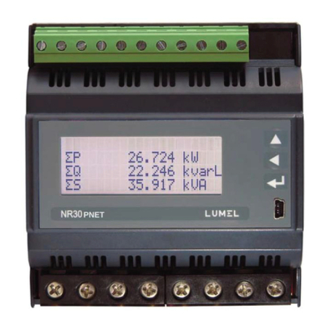
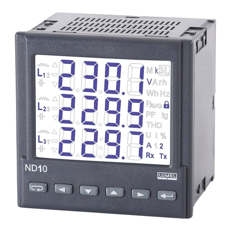
Lumel ND30 User manual

POWER NETWORK METER
ND30
USER’S MANUAL

Contents
1 APPLICATION................................................................................................................................2
2 METER SET...................................................................................................................................2
3 BASIC REQUIREMENTS, OPERATIONAL SAFETY....................................................................3
4 INSTALLATION..............................................................................................................................4
5 METER DESCRIPTION.................................................................................................................5
5.1 Current nputs ........................................................................................................................5
5.2 Voltage nputs.........................................................................................................................5
5.3 External connect on d agrams................................................................................................5
6 ND30 Programm ng.......................................................................................................................9
6.1 Front panel..............................................................................................................................9
6.2 Start ng work.........................................................................................................................11
7 OPERATING MODES..................................................................................................................12
7.1 Measurement mode..............................................................................................................16
7.1.1 Measurement of voltage and current harmon cs................................................................17
7.1.2 Analog nd cator .................................................................................................................17
7.2 Parameters mode.................................................................................................................18
7.3 Alarms mode.........................................................................................................................21
7.4 Analog output mode..............................................................................................................24
7.5 D splay mode........................................................................................................................25
7.6 Arch v ng mode.....................................................................................................................30
7.7 Ethernet mode......................................................................................................................34
7.8 Modbus mode.......................................................................................................................35
7.9 Sett ngs mode ......................................................................................................................35
7.10 Informat on mode ...............................................................................................................36
8 EXTENDED FUNCTIONALITY....................................................................................................37
9 MEASURING VALUES ARCHIVING...........................................................................................38
9.1 INTERNAL MEMORY...........................................................................................................38
9.2 COPYING ARCHIVE ...........................................................................................................38
9.3 ARCHIVE FILES STRUCTURE............................................................................................39
9.4 DOWNLOADING ARCHIVE ................................................................................................40
10 SERIAL INTERFACES...............................................................................................................40
10.1 RS485 INTERFACE – l st of parameters............................................................................40
10.2 Examples of reg sters' readout and wr te...........................................................................40
10.3 Ethernet nterface 10/100-BASE-T.....................................................................................43
10.3.1 Connect ng 10/100-BASE-T nterface........................................................................44
10.3.2 Web Server.................................................................................................................45
10.3.2.1 General v ew.......................................................................................................46
10.3.2.2 Web user select on .............................................................................................46
10.3.3 FTP Server.................................................................................................................47
10.3.3.1 FTP user select on...............................................................................................48
10.3.4 Modbus TCP/IP..........................................................................................................49
11 MAP OF ND30 METER REGISTERS........................................................................................50
12 SOFTWARE UPGRADE............................................................................................................75
12.1 Upgrade of the meter webs te............................................................................................75
12.2 F rmware update - ma n program of the meter...................................................................76
13 ERROR CODES........................................................................................................................77
14 TECHNICAL DATA.....................................................................................................................78
15 ORDERING CODE....................................................................................................................82

ND30-09D 2 User's manual
1 APPLICATION
The ND30 meter s a programmable d g tal nstrument des gned for the
measurement of 1-phase 2-w re and 3-phase 3 and 4-w re power network
parameters n balanced or unbalanced systems. The measured values are
d splayed on a 3,5’’ TFT full-color screen, resolut on: 320 x 240 p xel.
The meter enables control and opt m zat on of the power electron c dev ces,
systems and ndustr al nstallat ons.
The meter prov des measurement of: RMS of voltage and current, act ve,
react ve and apparent power, act ve, react ve and apparent energy, power
factors, frequency, the harmon cs of current and voltage /up to 51st/, THD of
voltage and current, averaged act ve and apparent power P Demand,
S Demand, averaged current I Demand /15, 30 or 60 m nutes/. Voltages and
currents are mult pl ed by g ven voltage and current rat os of the measur ng
transformers. Power and energy nd cat ons take nto account all
programmed rat o values. The value of each measured value can be
transm tted to the master system v a the RS-485 or Ethernet nterface.
Three relay outputs s gnal the overflow of the chosen value and
the programmable analog output maps the ass gned parameter.
The temperature nputs can be used to control the temperature
of the transformers w nd ngs, motors.
There s a galvan c separat on between follow ng un ts of the meter:
- supply
- voltage nputs
- current nputs
- RS485 nterface
- Ethernet nterface
- alarm outputs
- analog output
- temperature nput Pt100
2 METER SET
Complete set of the meter ncludes:
1. ND30 meter 1 pc
2. seal 1 pc
3. screw clamp to f x n the panel 4 pc

ND30-09D 3 User's manual
4. plug w th 16 screw term nals 1 pc
5. plug w th 14 screw term nals 1 pc
6. user's manual 1 pc
Fig. 1. Meter set
3 BASIC REQUIREMENTS, OPERATIONAL SAFETY
In terms of operat onal safety the controller meets the requ rements of the
EN 61010-1 standard.
Remarks concern ng safety:
The meter should be nstalled and connected only by a qual f ed
personnel. All relevant safety measures should be observed dur ng
nstallat on.
Always check the connect ons before turn ng the meter on.
Pr or to tak ng the meter hous ng off, always turn the supply off and
d sconnect the measur ng c rcu ts.

ND30-09D 4 User's manual
Removal of the meter hous ng dur ng the warranty per od vo ds the
warranty.
Th s meter conforms to all requ rements of the electromagnet c
compat b l ty n the ndustr al env ronment.
A sw tch or a c rcu t-breaker should be nstalled n the bu ld ng or
fac l ty. It should be located near the dev ce, eas ly access ble by the
operator, and su tably marked.
4 INSTALLATION
The meter s ntended to be f xed to the panel w th mount ng brackets as
presented on F g. 1. The meter hous ng s made of a self-ext ngu sh ng
plast cs.
Fig. 2. Meter fitting
Hous ng overall d mens ons 96 x 96 x 77 mm, d mens ons of the assembly
hole 92.5 x 92.5 mm. There are screw term nal str ps on the outer s de of
the meter wh ch enable the connect on of external w res of d ameter up to
2.5 mm2.
Fig. 3. Overall dimensions of the ND30 meter
1
2

ND30-09D 5 User's manual
5 METER DESCRIPTION
5.1 Current nputs
All current nputs are galvan cally solated ( nternal current transformers).
The meter s adapted to work w th external measur ng current transformers /
1 A or 5 A /. D splayed current values and der vat ve values are automat cally
converted n relat on to the ntroduced external current transformer rat o.
5.2 Voltage nputs
All voltage nputs are galvan cally solated ( nternal transformers). Values on
voltage nputs are automat cally converted accord ng to the ntroduced rat o
of the external voltage transformer. Voltage nputs are spec f ed n the order
as 3x57.7/100 V, 3x230/400 V or 3x110/190 V, 3x400/690 V.
5.3 External connect on d agrams
External connect ons are shown n F g. 4.
Fig. 4. Meter connections
opt on
Ethernet (opt on)

ND30-09D 6 User's manual
Fig. 5. Direct measurement, indirect and semi indirect in a 1 phase
network
D rect measurement
n 4-w re network
ND30
296 7431 1185
N
L1
L2
L3
ND30
296 7431 1185
L1
S
2
S
1
P
2
P
1
N
b
a
B
A
1
11 32
L1
S
2
S
1
P
2
P
1
N
1 3
N
L1
2 11

ND30-09D 7 User's manual
Fig. 6. Meter connections of input signals in a 3 phase 4 wire network
Sem - nd rect
measurement
n 4-w re network
L1
L2
L3
N
b
a
BA
b
a
BA
b
a
B
A
ND30
296 7431 1185
S
2
S
1
P
2
P
1
S
2
S
1
P
2
P
1
S
2
S
1
P
2
P
1
L1
L2
L3
N
b
a
BA
2
5
8
b
a
B
A
Ind rect measurement
n 4-w re network
ND30
296 7431 1185
L2
L3
N
S
2
S
1
P
2
P
1
S
2
S
1
P
2
P
1
S
2
S
1
P
2
P
1
L1

ND30-09D 8 User's manual
Fig. 7. Meter connections of input signals in a 3 phase 3 wire network
D rect measurement n
a 3-w re network
Sem - nd rect
measurement us ng 2
current transformers n
a 3-w re network
ND30
296 7431 1185
L2
L3
S
2
S
1
P
2
P
1
S
2
S
1
P
2
P
1
L1
L1
L2
L3
b
a
BA
b
a
BA
b
a
B
A
ND30
296 7431 1185
L1
L2
L3
b
a
BA
2
5
8
b
a
B
A
S
2
S
1
P
2
P
1
S
2
S
1
P
2
P
1
Ind rect measurement us ng 2
current transformers and 2 or 3
voltage transformers n a 3-w re
network
ND30
296 7431 1185
L1
L2
L3

ND30-09D 9 User's manual
6 ND30 PROGRAMMING
6.1 Front panel
Fig. 8. Front panel
The ND30 meter has 6 buttons and a full-color graph c screen.
Front panel descr pt on:
f1, ... , f8
8 f eld d splays - the d g ts
for readout and sett ngs,
DMD Averaged value nd cator (Demand)
V, A, W, var,
VA, Wh, varh,
Hz,
un ts of the d splayed
values
k, M k lo = 103, Mega = 106
U1, I1, P1, ...
..EnQ
d splayed parameters
mark ngs The markers nd cat ng the
nduct ve, capac ty load character
The values of the measured parameters are shown on the act ve pages
selected by subsequent press ng the buttons (next page) or
(prev ous page).
The page cons sts any 8 values selected from the Table 1 and d splayed
s multaneously on the d splay. The page def n t on s descr bed n the
Display mode. Depend ng on the locat on, meter buttons can perform
d fferent funct ons. Funct ons are descr bed n the bar on the bottom of the
screen. If the button lacks descr pt on, t s nact ve at the moment.

ND30-09D 10 User's manual
Fig. 9. Buttons marking – example
Informat on bar at the top of the screen d splays the status of the alarm
outputs, alarm cond t ons, T1 and T2 temperature of the sensors connected
to the f rst and second nput of PT100, f les arch ve memory status, arch ve
status, a symbol of Ethernet connect on, the nd cators of rece v ng and
transm tt ng data on the RS485 l nk, date and real-t me clock. A symbol
"phase sequence error" w ll be bl nk ng n case of a negat ve phase
sequence.
Fig. 10. Information bar
Icon Icon color Comments
Black – arch ve memory mounted
correctly
Black – no arch ve memory
Red – wrong f le system of the card
Copy ng from nternal memory to f les
arch ve memory. The f eld of percentage
of f les arch ve memory used flashes
blue wh le d splay ng the percentage of
copy ng progress.
Funkcja
przyc sku 2
Funkcja
przyc sku 3
Funkcja
przyc sku 1
Funkcja
przyc sku 4
Funkcja
przyc sku 5
Funkcja
przyc sku 6
Funct on
of button 1
Funct on
of button 2
Funct on
of button 3
Funct on
of button 4
Funct on
of button 5
Funct on
of button 6

ND30-09D 11 User's manual
Current state of the arch v ng:
Black – arch v ng n a group enabled,
wa t ng for the arch v ng cond t ons to be
met.
Red – the arch v ng cond t ons have
been met and sav ng the records s n
progress.
White – arch v ng n a group d sabled.
1st arch v ng group
2nd arch v ng group
Percentage of f les arch ve memory
used
Green background Value n the range 0 ... 70%
Orange background 70% of f les arch ve space
s full. It s recommended to
remove unnecessary f les
v a FTP.
Red background It s less than 7% of free
space n the f les arch ve
memory left. T me to
completely use a the f les
arch ve space s
approx mately 14 days at 1
sec. nterval. Immed ately
delete any unnecessary
f les v a FTP.
Percentage of the arch ve copy ng
progress.
Blue flash ng background Copy ng from nternal
memory to f les arch ve
memory n progress
6.2 Start ng work
After sw tch ng the supply on, the meter d splays the ND30 meter name,
vers on, current software vers on and MAC for the vers on w th Ethernet and
then moves to the measurement mode and last saved page. D splayed
nformat on:
ND30 v:1.00 – meter type, program vers on number
Bootloader v.01.05 – bootloader vers on number
U: 57.7/230.0 V – voltage vers ons
I: 1.0/5.0 A – current vers ons
MAC: AA:BB:CC:DD:EE:FF (for vers ons w th Ethernet)

ND30-09D 12 User's manual
Fig. 11. Screen of meter measuring mode
7 OPERATING MODES
The ND30 meter has 10 operat ng modes:
Measure – normal work mode. In the Measure mode the values are
d splayed accord ng to the pages that are preset at the factory or
conf gured by the user.
Parameters – meter parameters conf gurat on
Alarms – Alarm 1, Alarm 2 conf gurat on
Analog output – analog output conf gurat on
Display – d splayed pages conf gurat on
Archiving – arch ved values conf gurat on
Ethernet – Ethernet nterface conf gurat on
Modbus – RS485 nterface parameters conf gurat on
Settings – sett ngs: password, language, t me, date
Information – prev ew of a program vers on, ser al number, MAC address
To move from the Measure mode to any other mode, press the button
for approx. 3 seconds.
Buttons allow to select the appropr ate mode, to accept press the
button
To return to a measurement mode use the button
Menu
Select
Exit

ND30-09D 13 User's manual
Fig. 12a. Programming matrix
Voltage
transformer
secondary
00100.0
Parameters
Settings
Log cal
cond t ons
C1
C1 v C2 v C3
C1
C2
C3
(C1
C2
)
v
C3
(C1 v
C2)
C3
Relay state
f alarm on
off
on
Alarms
Alarm 1
Alarm 2
Current
Transformer
pr mary
Holdback
Alarm off
off
on
Demand
nteg. t me
AVG
synchron zat on
Pt100 re st
on np 1
Pt100 re st
on np 2
PT100 [
]
Delete energy
counters
Delete
demand
values
No
Yes
Connect on
w re
Current
nput range
1 A
5 A
Voltage nput
range
3x57.7/100 V
3x230/400 V
3 phase-4 w re
3 phase-3 w re.
1 phase-2 w re
00005
15 m n
30 m n
60 m n
lack
w th RTC
PT100
[
]0000.00
0000.00
No
act ve
react ve
apparent
all
Condition C1
Condition C2
Condition C3
Value
U1
I1
P1
Q1
:
gg:mm
Cond t on
type
n_on
noFF
on
oFF
H_on
:
3_oF
Delay to
cond t on off
[s]
0000
Low l m t
cond t on
[
%
]
+0099.0
D splay alarm
event
off
on
H gh l m t
cond t on
[
%
]
+0101.0
Delay to
cond t on on
[s]
0000
Holdback
cond t on
off->on
[s]
0000
D splay
cond t on
event
off
on
Analog
output
Value Output
range
0...20mA
4...20mA
Low l m t
nput.
[
%
]
+000.0
H gh l m t
nput [
%
]
+100.0
Low l m t
output
[mA]
0.00
H gh l m t
output
[mA]
20.00
Out mode
normal
low l m t
output
high limit
output
U1
I1
P1
Q1
:
gg:mm
or
3x110/190 V
3x400/690 V
Set
parameters
default
No
Yes
No
Yes
Set default
No
Yes
Set defaults
Voltage
Transformer
pr mary
0000100
Current
transformer
secondary
00005
Voltage
connector 2
U1
U2
U3
Voltage
connector 5
U1
U2
U3
Voltage
connector 8
U1
U2
U3
Current
connector 1-3
I1
-I1
I2
-I2
I3
-I3
Current
connector 4-6
I1
-I1
I2
-I2
I3
-I3
Current
connector 7-9
I1
-I1
I2
-I2
I3
-I3

ND30-09D 14 User's manual
Fig. 12b. Programming matrix
Fig. 12c. Programming matrix

ND30-09D 15 User's manual
Fig. 12d. Programming matrix

ND30-09D 16 User's manual
Fig. 12e. Programming matrix
7.1 Measurement mode
In the Measure mode the values are d splayed accord ng to the pages that
are preset at the factory or conf gured by the user n the Display mode.
Chang ng the page s done by press ng the buttons or .
Prev ew of the max mum or m n mum values respect vely s done wh le the
button or s pressed down. Reset of max mum or m n mum
values s done by press ng the button wh le v ew ng the r values, .e.
f rst the button or and then must be pressed.
S multaneously press ng the button and w ll copy nternal
memory to f les arch ve.
When react ve power or react ve nduct ve or capac ty energy s d splayed,
th s nd cat on s accompan ed by a symbol of the load character: for an
nduct ve load or for a capac ty load.
When d splay ng the act ve power, the s gn "+" s d splayed for act ve energy
mport or " " for act ve energy export.
Exceed ng of the upper or lower nd cat on range s s gnaled on the d splay
by or . For measurement of the averaged values (P DMD, S
DMD, I DMD) s ngle measurements are carr ed out w th 0.25 second
quantum. Averag ng t me to choose from: 15, 30 or 60 m nutes. Unt l all
samples of the averaged values are acqu red, the values are calculated
from already measured samples.
Current value n the neutral w re IN s calculated from phase current vectors.
Min
Min
Max
Del
Del
Max
Max Min
Modbus
Address Baudrate
4800 b/s
9600 b/s
19,2 kb/s
38,4 kb/s
57,6 kb/s
115,2 kb/s
Mode
001
RTU 8N2
RTU 8N1
RTU 8O1
RTU 8N1
Information
Type Order ng
code
12200
ND30
Loader
vers on
Program
vers on
0.60
Ser al
number
1.05
Settings
Password
****
Language T me
13.47
Date
08/09/2015
Default
sett ngs
Engl sh
Polsk
Deutsch
No
Yes
Default
sett ngs
reg. 42xx
No
yes
aa.bb.cc.00 21 01
MAC
address
18030006
DHCP
IP address
000.000.000.000
Subnet
mask
255.255.255.000
DNS
address
Default
gateway
000.000.000.000 008.008.008.008
Obta ned from DHCP or entered manually when
DHCP s off
Serv ce
code
12A49AD32EF7C98A12BC
off
on

ND30-09D 17 User's manual
7.1.1 Measurement of voltage and current harmon cs
The cho ce of harmon cs s done by select ng the pages ded cated to d splay
the values of voltage harmon cs U1, U2, U3 and currents I1, I2, I3
s multaneously for 3-phase (page 11). The number of a d splayed harmon cs
can be changed n the range of 2..51 by the buttons or
Page 12 shows a bar chart of the harmon cs for each phase: voltage at the
top and currents at the bottom of the screen. Page 12 shows a bar chart of
the harmon cs. The cho ce of d splayed harmon cs s done by press ng a
button . The button s used to select the groups of harmon cs:
harm2 - harm26, harm27 - harm52 or harm2 - harm51.
Fig. 13. Screens 11 and 12 visualization of harmonics
7.1.2 Analog nd cator
Page 13 shows the mapping of the selected quantity on the analog
indicator. The selection of displayed quantity is made in the Display
mode as described in item 7.5, by selecting page 13. Prev ew or
h d ng of the max mum or m n mum values takes place after press ng the
or button respect vely. Delet ng the max mum or m n mum
values s done by press ng the and then or button. If the
lower or upper scale threshold s exceeded, the message BOTTOM SCALE
or UPPER SCALE appears.
L1,2,3 +
Max Min
Del Max Min

ND30-09D 18 User's manual
Fig.13a. Screen 13 visualization of the analog indicator
7.2 Parameters mode
Th s mode s used to determ ne the parameters of the meter. To enter
Parameters mode press the button for approx. 3 seconds and next
us ng the button or select Parameters mode, to accept press the
button . The parameters conf gurat on mode s protected by a
password, f t was entered and t s d fferent from zero. The password
prompt s sk pped for the password 0000. If the password s ncorrect, the
message "Wrong password. Read only menu" s d splayed. Then t s
poss ble to v ew the parameters, but the changes are not poss ble.
Fig. 14. Screens while entering a password
If the password s correct or t has not been entered, you can set the values
accord ng to Table 2.
Buttons are used to choose the parameter, to accept press the
button . Then use the buttons to choose the features of a
parameter or set the requested parameter values, .e. you can choose the
d g t n the dec mal pos t on by the button or the d g t value by the
button or . The act ve pos t on s s gnaled by the cursor. Set value
or parameter can be accepted by the button or canceled by press ng
Menu
OK
Select
Select
Cancel

ND30-09D 19 User's manual
. Ex t from the Parameters procedure follows press ng s multaneously
the button or after wa t ng for approx. 120 seconds. Ex t from the
Select ng parameters menu follows press ng the button or after
wa t ng for approx. 120 seconds.
Fig. 15. Screens of Parameters mode
Cancel
Esc
Exit
Menu button m n. 3 sec.
Button
Select
The buttons
Button
Select
- cho ce
of the features
OK - acceptance
Cancel - res gnat on
Measurement
Table of contents
Other Lumel Measuring Instrument manuals
Popular Measuring Instrument manuals by other brands

PCE Health and Fitness
PCE Health and Fitness MiniAir20 operating instructions

CONDTROL
CONDTROL Vector 30 user manual

Transforming Technologies
Transforming Technologies Resistance RANGER CM2800 instruction manual

A.R.C. Laser
A.R.C. Laser Nuvolas user manual

WT sensor
WT sensor PCRL02 quick start guide

dlb
dlb AIJGO-61 instruction manual