Sonel WMGBMRU120 User manual

MRU-120 –USER MANUAL
2

USER MANUAL
EARTH RESISTANCE METER
MRU-120
SONEL S. A.
Wokulskiego 11
58-100 Świdnica
Version 2.10 28.03.2022

MRU-120 –USER MANUAL
2
The MRU-120 meter is a modern, easy and safe measuring device. Please acquaint yourself with the
present manual in order to avoid measuring errors and prevent possible problems related to opera-
tion of the meter.

MRU-120 –USER MANUAL
3
TABLE OF CONTENTS
1Safety ................................................................................................................5
2Menu..................................................................................................................6
2.1 Measurement settings.............................................................................................. 6
2.1.1 Mains frequency...........................................................................................................................7
2.1.2 Calibration of the measurement clamp C-3.................................................................................7
2.1.3 Earth resistivity settings................................................................................................................9
2.2 Meter settings...........................................................................................................9
2.2.1 LCD contrast.................................................................................................................................9
2.2.2 AUTO-OFF settings ...................................................................................................................10
2.2.3 Display settings ..........................................................................................................................10
2.2.4 Date and time.............................................................................................................................10
2.2.5 Battery discharging.....................................................................................................................11
2.2.6 Program update..........................................................................................................................11
2.3 Language choice.................................................................................................... 11
2.4 Information on the manufacturer............................................................................11
3Measurements................................................................................................12
3.1 Measurement of resistance of earth connection and equipotential bonding (2P) .........12
3.2 Calibration of the test leads ................................................................................... 13
3.2.1 Auto-zeroing on ..........................................................................................................................13
3.2.2 Auto-zeroing off...........................................................................................................................14
3.3 Earth resistance measurement with 3-pole method (RE3P)................................... 15
3.4 Earth resistance measurement with 4-wire method (RE4P)...................................18
3.5 Earth resistance measurement with 3-pole method with additional clamp (RE3P+C)...21
3.6 Earth resistance measurement with two-clamp method (2C).................................24
3.7 Earth resistivity measurement (ρ) ..........................................................................26
4Memory ...........................................................................................................29
4.1 Saving of the measurement results in the memory................................................ 29
4.2 Memory erasing ..................................................................................................... 30
4.3 Memory browsing................................................................................................... 31
5Data transmission..........................................................................................32
5.1 Computer connection accessories.........................................................................32
5.2 Connection of the meter to a computer..................................................................32
6Power supply..................................................................................................32
6.1 Monitoring of the power supply voltage.................................................................. 32
6.2 Replacement of accumulators................................................................................33
6.3 Fuse replacement ..................................................................................................34
6.4 Charging of accumulators......................................................................................34
6.5 Discharging of accumulators..................................................................................35
6.6 General principles regarding using Ni-MH accumulators....................................... 36
7Cleaning and maintenance ...........................................................................37
8Storage............................................................................................................37
9Dismantling and disposal .............................................................................37

MRU-120 –USER MANUAL
4
10 Technical data................................................................................................ 38
10.1 Basic data...............................................................................................................38
10.2 Additional data........................................................................................................40
10.2.1 Influence of the serial interference voltage UNupon earth resistance measurements for
functions RE3P, RE4P, RE3P+C................................................................................................40
10.2.2 Influence of the serial interference voltage UNupon earth resistance measurements for
function ρ....................................................................................................................................40
10.2.3 Influence of the auxiliary electrodes upon earth resistance measurements for
function RE3P, RE4P, RE3P+C..................................................................................................40
10.2.4 Influence of the auxiliary electrodes upon earth resistance measurements for function ρ......41
10.2.5 Influence of the interference current Ilupon the result of the earth resistance measurement for
method RE3P+C........................................................................................................................41
10.2.6 Influence of interference current on the result of the earth resistance measurement for two-
clamp method (2C)....................................................................................................................41
10.2.7 Influence of the relation of the resistance measured with clamp for the multiple earthing
branch to the resultant resistance (RE3P+C)............................................................................41
10.2.8 Additional uncertainties in accordance with IEC 61557-4 (2P)................................................42
10.2.9 Additional uncertainties in accordance with IEC 61557-5 (RE3P, RE4P, RE3P+C).................42
11 Accessories ................................................................................................... 42
11.1 Standard accessories.............................................................................................42
11.2 Optional accessories..............................................................................................43
12 Positions of the meter’s cover ..................................................................... 44
13 Manufacturer.................................................................................................. 44
14 Laboratory services ...................................................................................... 45

MRU-120 –USER MANUAL
5
1 Safety
The MRU-120 meter has been designed to realise measurements whose results determine the
safety conditions of the installation. Therefore, in order to provide conditions for correct operation and
the correctness of the obtained results, the following recommendations must be observed:
Before you proceed to operate the meter, acquaint yourself thoroughly with the present
manual and observe the safety regulations and specifications determined by the producer,
in particular concerning accessories.
The MRU-120 meter has been designed for the purpose of measurements of earth connection
and equipotential bonding, ground resistivity, as well as clamps current measurements. Any ap-
plication that differs from those specified in the present manual may result in a damage to the de-
vice and constitute a source of danger for the user.
The device must be operated solely by appropriately qualified personnel with relevant certificates
to realise measurements of electric installation. Operation of the meter realised by unauthorised
personnel may result in damage to the device and constitute a source of danger for the user.
Using this manual does not exclude the need to comply with occupational health and safety regu-
lations and with other relevant fire regulations required during the performance of a particular type
of work. Before starting the work with the device in special environments, e.g. potentially fire-
risk/explosive environment, it is necessary to consult it with the person responsible for health and
safety.
It is unacceptable to operate the following:
A damaged meter which is completely or partially out of order,
A meter with damaged test leads insulation,
A meter stored for an excessive period of time in disadvantageous conditions (e.g. exces-
sive humidity). If the meter has been transferred from a cool to a warm environment of
a high level of relative humidity, do not realise measurements until the meter has
been warmed up to the ambient temperature (approximately 30 minutes).
Before measurements may commence, make sure the test leads are connected to the appropri-
ate measurement sockets.
Do not operate a meter with an open or incorrectly closed battery (accumulator) compartment or
power it from other sources than those specified in the present manual.
The meter’s inputs are electronically protected from power surge, as a result for example, of ac-
cidental connection to the power supply source:
- for all input combinations –up to 276 V for 30 seconds.
Repairs may be realised solely by an authorised service point.
The device complies with the following norms; EN 61010-1 and EN 61557-1, -4, -5.
Note:
The manufacturer reserves the right to modify the appearance, accessories and
technical data of the meter.

MRU-120 –USER MANUAL
6
2 Menu
The menu is available at any position of the knob.
Press MENU.
Using buttons and highlight
the required position.
Press ENTER to select the option.
2.1 Measurement settings
Using buttons and highlight
the required position.
Press ENTER to select the option.

MRU-120 –USER MANUAL
7
2.1.1 Mains frequency
It is necessary to determine the frequency of the mains which is the source of potential interfer-
ence in order to select the appropriate frequency of the measurement signal. Solely measurements
based upon the correct frequency of the measurement signal will guarantee the optimum interference
filtering. The meter is adapted for filtering of interference from 50 Hz and 60 Hz networks.
Using buttons and select
the frequency and
press ENTER to select the option.
2.1.2 Calibration of the measurement clamp C-3
The clamp bought apart for a meter that was purchased before must be calibrated before it is
used for the first time. It may be periodically calibrated in order to avoid the influence of the ageing
elements upon the resolution of measurements. The procedure of calibration must be realized also
after clamp has been replaced.
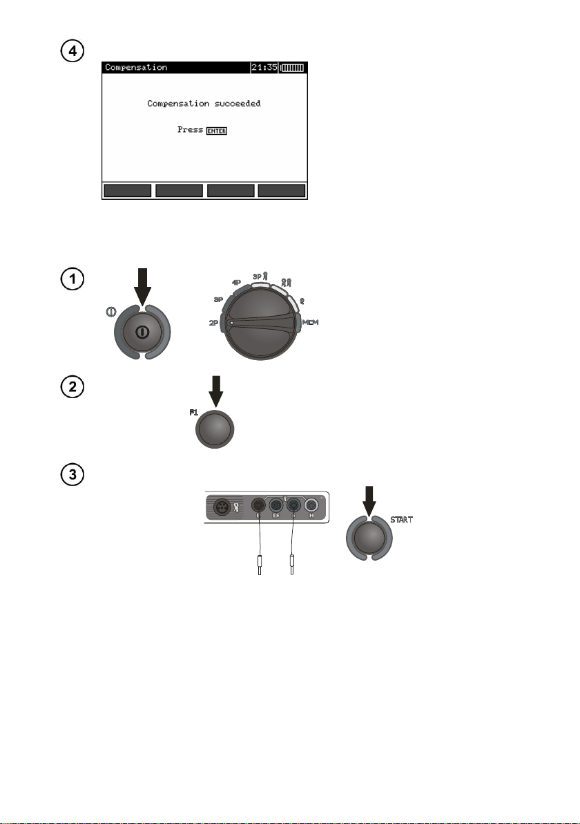
Having read the preliminary infor-
mation ENTER.
Follow the displayed instructions.
MRU-120 –USER MANUAL
8
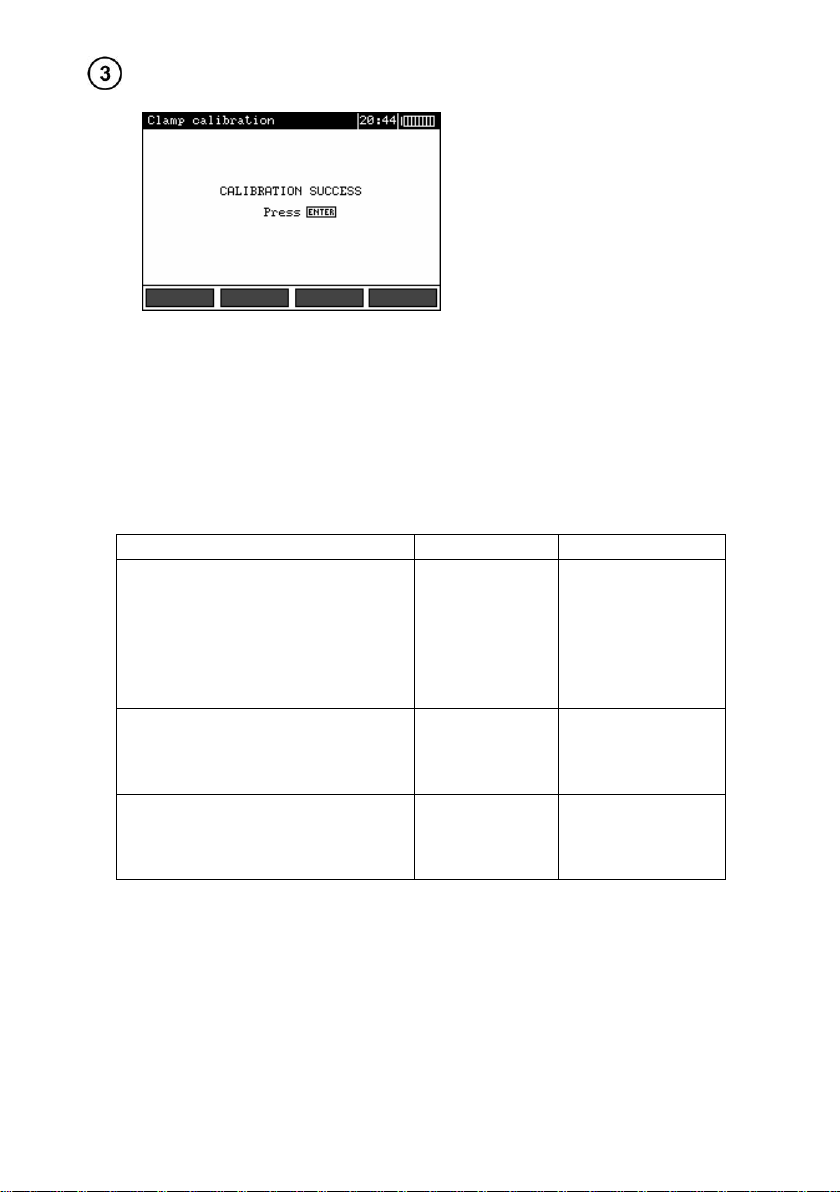
Once the calibration has been successfully concluded,
The following will be displayed.
The meter has determined the correction factor for connected clamp. The factor is saved in the
memory also when the power supply of the meter is off until the following successful calibration of the
clamp has been performed.
Notes:
- Make sure the test lead passes centrally through the clamp.
Additional information displayed by the meter
Message
Cause
Procedure
ERROR: CLAMP NOT CONNECTED
OR NOT PUT ON WIRE
CONNECTED TO H AND E SOCKET!
CALIBRATION ABORTED.
PRESS ENTER
The clamp is not
connected
Check whether the
clamp is connected
to the device or
whether it is placed
upon the test lead
used by the meter
to force the pas-
sage of current.
ERROR: WIRE NOT CONNECTED
TO H AND E TERMINAL!
CALIBRATION ABORTED.
PRESS ENTER
No wire
Revise the connec-
tions
ERROR: CALIBRATION
COEFFICIENT OUT OF RANGE.
CALIBRATION ABORTED.
PRESS ENTER
Incorrect calibra-
tion factor
Check the quality of
the connections
and/or replace the
clamp.

MRU-120 –USER MANUAL
9
2.1.3 Earth resistivity settings
Using buttons , ,
and select the result and the
distance unit and press
ENTER to confirm.
2.2 Meter settings
Using buttons , select
required item. Press ENTER to
confirm.
2.2.1 LCD contrast
Using the buttons and set the contrast value and press ENTER.

MRU-120 –USER MANUAL
10
2.2.2 AUTO-OFF settings
The setting determines the time before the automatic turning-off of the device when it is not in use.
Use buttons and to set the time or AUTO-OFF disable, press ENTER.
2.2.3 Display settings
The setting permits to turn on/off the setting bar display. Use buttons and to set the dis-
play of the setting bar (measurement parameters), press ENTER.
Visible bar
Hidden bar
2.2.4 Date and time
Use buttons and to select
the value to be modified (Day,
month, hour, minute).
Use buttons and to set
the value. Once the date and
time have been set, press
ENTER.
MRU-120 –USER MANUAL
11
2.2.5 Battery discharging
The procedure is fully described in chapter 6.4.
2.2.6 Program update
NOTE!
Before you proceed to programming, charge the accumulators.
During programming do not turn the meter off or
disconnect the transmission cable.
Before you proceed to updating the programme, download from the manufacturer’s web page
(www.sonel.pl) the meter programming software, install it in the computer and connect the meter to
the computer.
Having chosen the Program update in the MENU, proceed in accordance with the instructions
displayed by the programme.
2.3 Language choice
Use buttons and to select **Language choice** in the main MENU and press ENTER.
Use buttons and to select the language and press ENTER.
2.4 Information on the manufacturer
Use buttons and in order to select Product info and press ENTER.
MRU-120 –USER MANUAL
12
3 Measurements
Note:
During measurements the status bar is displayed.
3.1 Measurement of resistance of earth connection and equipotential
bonding (2P)
Note:
The measurement complies with the requirements specified
in the standard EN 61557-4 (U<24 V, I>200 mA for R≤10 Ω).
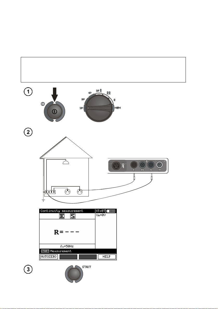
Turn the meter on.
Set the rotational
function selector at 2P.
Connect the object being measured to the terminals Sand Eof the meter.
The meter is ready for measurement.
The auxiliary display shows the value
of the interference voltage and its fre-
quency. The setting bat shows the
mains frequency set in the MENU.
Press START In order for the test to
commence.

MRU-120 –USER MANUAL
13
Read out the result.
The result is displayer for 20 s.
It may be displayed again ENTER is
pressed.
Additional information displayed by the meter
R>20,0kΩ
Measurement range exceeded.
UN>40V! and a con-
tinuous sonic signal
The voltage on the measurement points exceeds 40 V,
the measurement is blocked.
UN>24V!
The voltage on the measurement points exceeds 24 V
but lower than 40 V, the measurement is blocked.
NOISE!
The value of the interfering signal is too high,
the result may be distorted by additional uncertainty.
3.2 Calibration of the test leads
In order to eliminate the influence of the resistance of the test leads over the result of the meas-
urement, it is possible to realise its compensation (auto-zeroing). In order to do so the measurement
function 2P includes the AUTOZERO subfunction.
3.2.1 Auto-zeroing on
Turn the meter on.
Set the rotational
function selector at 2P.
Press F1.
Follow the displayed instructions.
E S
CATI V 300V
MRU-120 –USER MANUAL
14
Once the auto-reset function Has concluded the following will be displayed:
Auto-zeroing is signalled by the legend AUTOZERO on the right-hand side of the display.
3.2.2 Auto-zeroing off
Turn the meter on.
Set the rotational
function selector at 2P.
Press F1.
Separate the test leads. Press START.
S
E
C AT I V 30 0V
Once the auto-zeroing function has been turned off, the legend AUTOZERO will be no long-
er displayed.
Note:
- It is sufficient to realise compensation once for the given test leads. It is also remembered once the
meter has been turned off.

MRU-120 –USER MANUAL
15
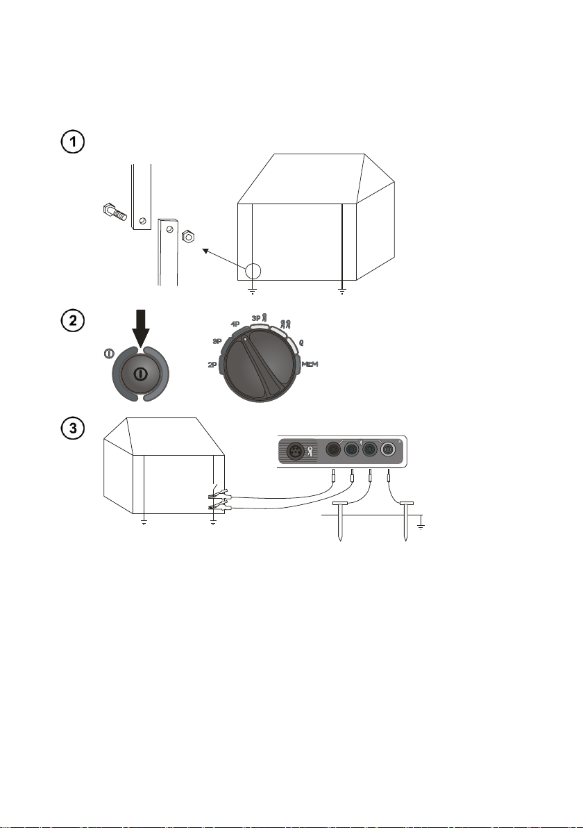
3.3 Earth resistance measurement with 3-pole method (RE3P)
The basic kind of the earth resistance measurement is 3-pole measurement.
Disconnect the tested earth electrode for the object installation.
Turn the meter on.
Set the rotational
function selector at 3P.
E S H
CATIV 300V
Connect the current electrode driver into ground to the Hsocket of the meter.
Connect the voltage electrode driver into ground to the Ssocket of the meter.
Connect the tested earth electrode to the Esocket of the meter.
The tested earth electrode as well as the current electrode and voltage electrode
should be aligned.
The meter is ready for measurement.
The auxiliary display shows the value of
the interference voltage and its fre-
quency. The setting bar shows the
mains frequency set in the MENU.
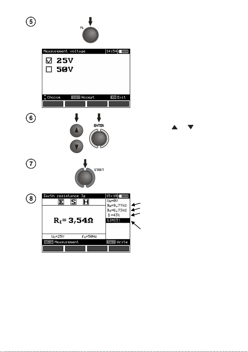
MRU-120 –USER MANUAL
16
Press F1 to order to modify the
measuring voltage.
Use buttons and to set the
measuring voltage and press
ENTER.
Press START In order for the test to
commence measurement.
Read out the result.
Current electrode resistance
Voltage electrode resistance
Additional uncertainty caused by the
resistance of the electrodes
Displayed, when δ>30%
The result is displayer for 20 s.
It may be displayed again ENTER is
pressed.

MRU-120 –USER MANUAL
17
S
Repeat the measurements (see points 3, 7 and 8) moving
the voltage electrode by a couple of meters: approaching it to
and moving it away from the tested earth electrode.
If the REtest results differ more than 3%, then it is necessary
to increase significantly the distance between the current
electrode from the earth electrode in question and repeat the
measurement.
Note:
Earth resistance measurement may be realised if the interference voltage does
not exceed 24 V. The interference voltage is measured up to 100 V. Do not con-
nect the meter to a voltage exceeding 100 V.
- Pay particular attention to the quality of the connection of the tested object with the test leads –
the contact area must be cleaned of paint, rust, etc.
- If the resistance of the auxiliary electrodes is too high, then the measurement of the REearth elec-
trode will be distorted by additional uncertainty. A particularly high measurement uncertainty is gen-
erated if we measure a low value of the earth resistance with electrodes of a weak contact with the
ground (such a situation occurs often if the earth electrode is properly made and the upper layer of
the ground is dry and characterised by a low conductivity). Then the relation between the electrode
resistance and the resistance of the measured earthing is very high, and so is the case of the meas-
urement uncertainty which depends on it. What may be done then is to perform, in accordance with
the formulae specified in point 10.2, calculations, which will permit to evaluate the influence of the
measurement conditions. It is also possible to improve the contact of the electrode with the ground,
for example by means of moistening of the place when the electrode is driven, its driving into the
ground in another place or using a 80-centimetre electrode. Check also the test leads and make sure
the insulation is not damaged and the contacts: test lead –banana plug –electrode are not corroded
or loosened. In most cases the achieved resolution of the measurement is sufficient, but it is neces-
sary to be conscious of the uncertainty the measurement is burdened with.
- If the resistance of Hand Selectrodes or one of them exceeds 19.9 kΩ, an appropriate message is
displayed: "R_H and R_S electrodes resistance are higher than 19.9 kΩ! Measurement impos-
sible!".
- Manufacturer’s calibration doesn’t include the resistance of test leads. Displayed result is sum of
measured object and test leads resistance. However, in the meters up to No. 77, the factory calibra-
tion takes into account the resistance of only 2.2 m leads.
Additional information displayed by the meter
RE>20,0kΩ
Measurement range exceeded.
UN>40V! and a con-
tinuous sonic signal
The voltage on the measurement points exceeds 40 V,
the measurement is blocked.
UN>24V!
The voltage on the measurement points exceeds 24 V
but lower than 40 V, the measurement is blocked.
LIMIT!
The uncertainty of the electrode resistance >30%. (Uncer-
tainties calculated on the basis of the measured values)
NOISE!
The value of the interfering signal is too high,
the result may be distorted by additional uncertainty.
MRU-120 –USER MANUAL
18
3.4 Earth resistance measurement with 4-wire method (RE4P)
The 4-wire method is recommended in the case of measurements of earth resistance of very low
values. It permits to eliminate the influence of the test leads resistance over the result of the meas-
urement. In order to evaluate the resistance of the ground it is recommended to use the dedicated
measurement function (point 3.9).
Disconnect the tested earth electrode for the object installation.
Turn the meter on.
Set the rotational
function selector at 4P.
E S H
E ES S H
CATIV 300V
ES
Connect the current electrode driver into ground to the Hsocket of the meter.
Connect the voltage electrode driver into ground to the Ssocket of the meter.
Connect the tested earth electrode to the Esocket of the meter.
Connect the ES socket to the earth electrode below the E cable.
The tested earth electrode as well as the current electrode and voltage electrode
should be aligned.
This manual suits for next models
1
Table of contents
Other Sonel Measuring Instrument manuals

Sonel
Sonel CMP-1010 User manual

Sonel
Sonel WMGBCMP3kR User manual

Sonel
Sonel MRU-120HD User manual

Sonel
Sonel MRU-30 User manual

Sonel
Sonel CMP-401 User manual

Sonel
Sonel LMW-100 User manual

Sonel
Sonel LMW-100 User manual

Sonel
Sonel MMR-640 User manual

Sonel
Sonel LXP-2 User manual

Sonel
Sonel MPI-535 User manual

Sonel
Sonel CMP-402 User manual

Sonel
Sonel MMR-620 User manual

Sonel
Sonel MMR-630 User manual

Sonel
Sonel KT-800M User manual

Sonel
Sonel MZC-304 User manual

Sonel
Sonel CMP-1015-PV User manual

Sonel
Sonel PQM-702 User manual

Sonel
Sonel MIC-10 User manual

Sonel
Sonel PQM-707 User manual

Sonel
Sonel WMGBMZC304F User manual


