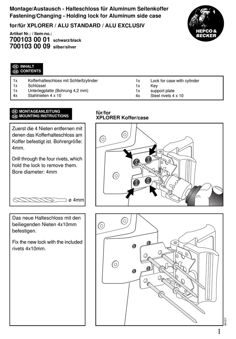
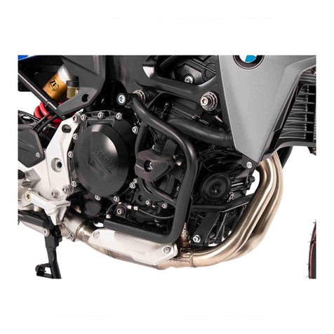
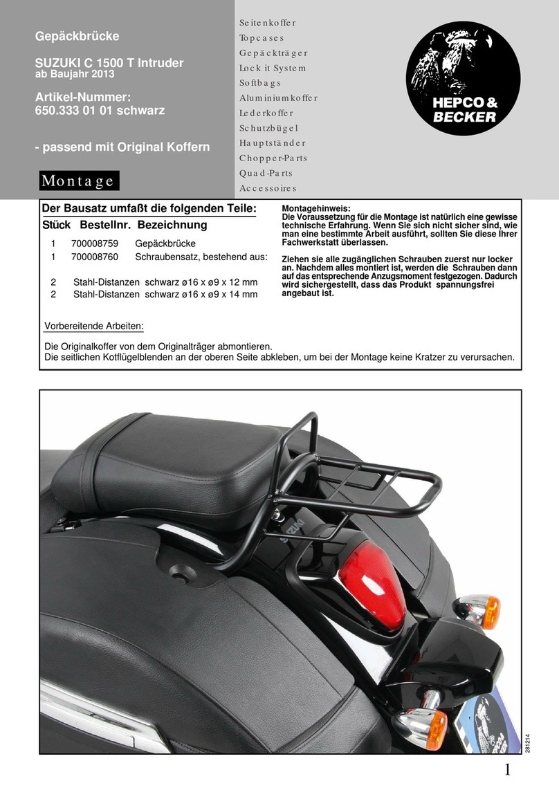
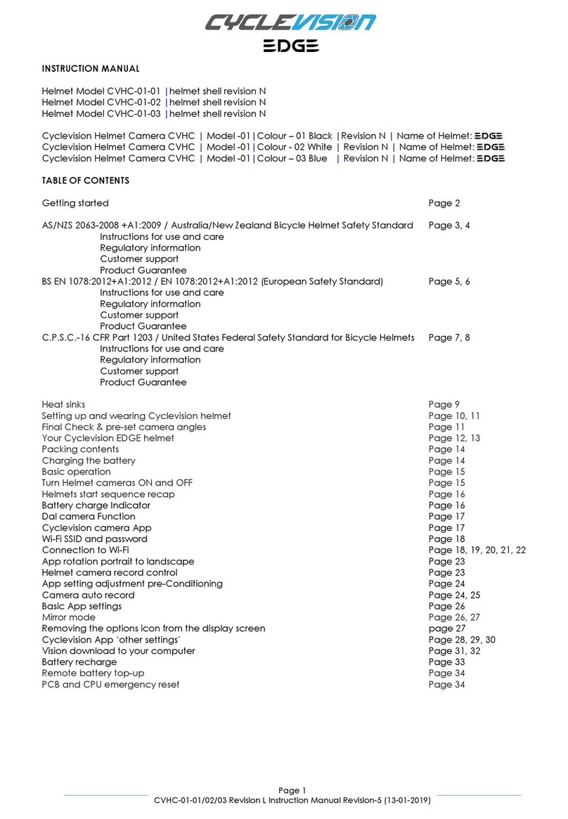
manuals.online logo
Brands
  1. Home
  2. •
  3. Brands
  4. •
  5. hepco & becker
  6. •
  7. Motorcycle Accessories
  8. •
  9. hepco & becker 5017581 00 01 User manual

hepco & becker 5017581 00 01 User manual

1
Motorschutzbügel/ Engine guard
140619/300919/220621/121021/180122/280122/040222/170222/280222/160522/190522/131222
INHALT
CONTENT
1x 700010419 Motorschutzbügel links Edelstahl
1x 700010420 Motorschutzbügel rechts Edelstahl
ODER
1x 700010421 Motorschutzbügel links schwarz
1x 700010422 Motorschutzbügel rechts schwarz
ODER
1x 700010423 Motorschutzbügel links orange
1x 700010424 Motorschutzbügel rechts orange
ODER
1x 700011832 Motorschutzbügel links gelb
1x 700011833 Motorschutzbügel rechts gelb
1x 700010425 Adapter links schwarz
1x 700010426 Adapter rechts schwarz
1x 700010427 Schraubensatz:
1x 700010419 Engine guard left stainless steel
1x 700010420 Engine guard right stainless steel
OR
1x 700010421 Engine guard left black
1x 700010422 Engine guard right black
OR
1x 700010423 Engine guard left orange
1x 700010424 Engine guard right orange
OR
1x 700011832 Engine guard left yellow
1x 700011833 Engine guard right yellow
1x 700010425 Adapter left black
1x 700010426 Adapter right black
1x 700010427 Screw kit:
1x Zylinderschraube ISK M8x50
1x Zylinderschraube ISK M8x90
1x Zylinderschraube ISK M8x70
2x Zylinderschraube ISK M8x40
1x Zylinderschraube ISK M8x35
4x Zylinderschraube ISK M8x20
4x Zylinderschraube ISK M6x25
4x Aludistanz Ø18xØ7x5
2x Aludistanz Ø16xØ9x31
1x Aludistanz Ø30xØ9x36
1x Aludistanz Ø30xØ9x16
2x Aludistanz Ø15xØ9x20
1x Aludistanz Ø15xØ9x10
1x Aludistanz Ø15xØ9x25
4x Karosseriescheibe Ø6,4xØ18
8x U-Scheibe Ø8,4
2x Karosseriescheibe Ø8,4xØ23
1x Allen screw M8x50
1x Allen screw M8x90
1x Allen screw M8x70
2x Allen screw M8x40
1x Allen screw M8x35
4x Allen screw M8x20
4x Allen screw M6x25
4x Alu spacer Ø18xØ7x5
2x Alu spacer Ø16xØ9x31
1x Alu spacer Ø30xØ9x36
1x Alu spacer Ø30xØ9x16
2x Alu spacer Ø15xØ9x20
1x Alu spacer Ø15xØ9x10
1x Alu spacer Ø15xØ9x25
4x Body washer Ø6,4xØ18
8x Washer Ø8,4
2x Body washer Ø8,4xØ23
KTM 890 Adventure / R / Rally
(2021-)
Artikel Nr.: / Item-no.:
5017617 00 01 schwarz/black
5017617 00 06 orange
5017617 00 22
edelstahl/stainless steel
HUSQVARNA Norden 901
(2022-)
Artikel Nr.: / Item-no.:
5017634 00 01 schwarz/black
5017634 00 08 gelb/yellow
5017634 00 22
5017581 00 22
edelstahl/stainless steel
KTM 790 Adventure / R
(2019-)
Artikel Nr.: / Item-no.:
5017581 00 01 schwarz/black
5017581 00 06 orange
2
5017581 00 xx / 5017617 00 xx / 5017634 00 xx
WICHTIG
IMPORTANT
Beachten Sie die in Ihrem Land geltenden Zulassungsbestimmungen.
Für den Bereich der BRD gilt: Ein Eintrag in die Fahrzeugpapiere ist nicht erforderlich.
Die Voraussetzung für die Montage ist natürlich eine gewisse technische Erfahrung. Wenn Sie sich nicht sicher sind,wie
man eine bestimmte Arbeit ausführt, sollten Sie diese Ihrer Fachwerkstatt überlassen.
Ziehen sie alle zugänglichen Schrauben zuerst nur locker an. Nachdem alles montiert ist, werden die Schrauben dann auf
das entsprechende Anzugsmoment festgezogen. Dadurch wird sichergestellt, dass das Produkt spannungsfrei angebaut ist.
Anzugsmomente beachten! Nach der Montage alle Verschraubungen auf festen Sitz kontrollieren!
Of course, the assembly requires a certain technical experience. If you are not sure how to execute a determined action,
you should ask your local distributor to do it. First, tighten all screws only loosely. After mounting all parts, the screws
should be tightened to the torque specified. This guarantees, that the product is mounted without tension. Observe
the tightening torques of the manufacturer! Control all screw connections after the assembling for tightness!
ACHTUNG
CAUTION
Immer nur eine Seite nach der anderen montieren bzw. Originalschrauben demontieren.
Ansonsten besteht die Gefahr, dass sich der Motor absenkt.
Mount one side after the other respectively remove original screws.
Otherwise, there is the risk that the engine block change position.
BENÖTIGTE WERKZEUGE
TOOLS REQUIRED
3
5017581 00 xx / 5017617 00 xx / 5017634 00 xx
MONTAGEANLEITUNG
MOUNTING INSTRUCTIONS
1
1x
1x
2x 1x
1x
Montage des Adapters rechts:
Die Montage erfolgt an den freien Gewinden
am Motorblock hinten: Mit der Zylinderschraube
M8x40 sowie U-Scheibe Ø8,4. Zwischen
Adapter und Motorblock die Aludistanz
Ø15xØ9x20 fügen.
Vorne: Mit der Zylinderschraube M8x50 sowie
U-Scheibe Ø8,4. Zwischen Adapter und
Motorblock die Aludistanz Ø15xØ9x25
fügen. Verkleidung wieder montieren!
Fastening of the adapter right:
The adapter is mounted on the free threads
at the rear of the engine block: With Allen
screws M8x40 and washers Ø8.4. Insert
aluminium spacer Ø15xØ9x20 between the
adapter and the engine block.
Front: With the Allen screw M8x50 and
washers Ø8.4. Join the aluminium spacer
Ø15xØ9x25 between the adapter and the
engine block. Reassemble the cover!
Fahrtrichtung/driving direction
VORBEREITUNG
PREPARING
Vor Beginn der jeweiligen Seite müssen die
beiden Schrauben unterhalb des Kühlers
(Abb.2) sowie die Schraube inkl. Hülse der
Rahmenbefestigung (Abb.3) hinter dem Kühler
entfernt werden, alle Schrauben und Hülsen
entfallen. Die seitliche Verkleidung entfernen,
hierfür die 3 Schrauben entfernen (Abb.2).
Auf der rechten Seite die vordere Schraube im
Motorblock entfernen (Abb.1).
Before starting the respective side, the two
screws underneath the cooler (Fig.2) as
well as the screw incl. sleeve of the frame
fastening (Fig.3) behind the cooler must be
removed, all screws and sleeves are omitted.
Remove the side cover by removing the 3
screws (Fig.2).
Remove the front screw in the engine block
on the right side (Fig.1).
Abb.1/Fig 1
Abb.3/Fig 3
Abb.2/Fig 2
4
5017581 00 xx / 5017617 00 xx / 5017634 00 xx
MONTAGEANLEITUNG
MOUNTING INSTRUCTIONS
4
2x 2x
Montage Motorschutzbügel rechts hinten:
Die Montage erfolgt am Adapter mit
den Zylinderschrauben M8x20 sowie
U-Scheiben Ø8,4.
Fastening of the engine guard right rear:
On the adapter with allen screws
M8x20 and washers Ø8,4.
Fahrtrichtung/driving direction
3
2x 2x 2x
Montage Motorschutzbügel rechts vorne:
Die Montage erfolgt an den nun freien
Gewinden mit den Zylinderschrauben
M6x25 sowie Karosseriescheiben Ø6,4x
Ø18. Zwischen Lasche und Gewinde die
Aludistanzen Ø18xØ7x5 fügen.
Fastening of the engine guard right front:
On the free threads with the allen screws
M6x25
and body washers
Ø6,4xØ18
.
Insert the alu spacers
Ø18xØ7x5
between
the lugs and the threads.
2
1x 1x 1x
Montage Motorschutzbügel rechts oben:
Die Montage erfolgt mit der Zylinderschraube
M8x70 sowie Karosseriescheibe Ø8,4xØ23.
Vorab die Aludistanz Ø16xØ9x31 in die
Gummihülse drücken. Zwischen Lasche und
Gummihülse die Aludistanz Ø30xØ9x16
fügen.
Fastening of the engine guard right top:
With allen screw M8x70 and body washer
Ø8,4xØ23.
First press the alu spacer Ø16xØ9x31 into
the rubber sleeve. Insert the second alu
spacer Ø30xØ9x16 between the
lug and the rubber sleeve.
Fahrtrichtung/driving direction
1x
5
5017581 00 xx / 5017617 00 xx / 5017634 00 xx
MONTAGEANLEITUNG
MOUNTING INSTRUCTIONS
6
1x 1x 1x
Montage Motorschutzbügel links oben:
Die Montage erfolgt mit der Zylinderschraube
M8x90 sowie Karosseriescheibe Ø8,4xØ23.
Vorab die Aludistanz Ø16xØ9x31 in die
Gummihülse drücken.
Zwischen Lasche und Gummihülse die Aludis-
tanz Ø30xØ9x36 fügen.
Fastening of the engine guard left top:
With allen screw M8x90 and body
washer Ø8,4xØ23.
First press the alu spacer Ø16xØ9x31 into
the rubber sleeve.
Insert the second alu spacer Ø30xØ9x36
between the lug and the rubber sleeve.
Fahrtrichtung/driving direction
1x
5
1x
1x 1x 1x
Montage des Adapters links:
Vorderer Verschraubungspunkt:
Die Montage erfolgt am freien Gewinde am
Motorblock mit der Zylinderschraube M8x40
sowie U-Scheibe Ø8,4. Zwischen Adapter und
Motor die Aludistanz Ø15xØ9x20 fügen.
Hinterer Verschraubungspunkt:
Die Montage erfolgt am freien Gewinde am
Motorblock mit der Zylinderschraube M8x35
sowie U-Scheibe Ø8,4. Zwischen Adapter und
Motor die Aludistanz Ø15xØ9x10 fügen.
Verkleidung wieder montieren!
Fastening of the adapter left:
Front bolting point:
At the free thread at the engine block with
allen screw M8x40 and washer Ø8,4.
Between adapter and engine add the alu
spacer Ø15xØ9x20.
Rear bolting point:
At the free thread at the engine block with
allen screw M8x35 and washer Ø8,4.
Between adapter and engine add the alu
spacer Ø15xØ9x10.
Reassemble the side cover!
Fahrtrichtung/driving direction
2x

This manual suits for next models

8

Other hepco & becker Motorcycle Accessories manuals
hepco & becker Krauser 4004.030.131 User manual

hepco & becker

hepco & becker Krauser 4004.030.131 User manual

hepco & becker 6307506 00 01 User manual

hepco & becker

hepco & becker 6307506 00 01 User manual

hepco & becker 502901 00 01 User manual

hepco & becker

hepco & becker 502901 00 01 User manual

hepco & becker Lock-it 5064564 00 01 User manual

hepco & becker

hepco & becker Lock-it 5064564 00 01 User manual

hepco & becker 4212554 00 01 User manual

hepco & becker

hepco & becker 4212554 00 01 User manual

hepco & becker 8107524 00 09 User manual

hepco & becker

hepco & becker 8107524 00 09 User manual

hepco & becker 5014550 00 05 User manual

hepco & becker

hepco & becker 5014550 00 05 User manual

hepco & becker Easyrack 661755 01 01 User manual

hepco & becker

hepco & becker Easyrack 661755 01 01 User manual

hepco & becker 4223999 00 01 User manual

hepco & becker

hepco & becker 4223999 00 01 User manual

hepco & becker 611.793 00 02 Installation guide

hepco & becker

hepco & becker 611.793 00 02 Installation guide

hepco & becker 653554 00 01 User manual

hepco & becker

hepco & becker 653554 00 01 User manual

hepco & becker 6604552 01 01 User manual

hepco & becker

hepco & becker 6604552 01 01 User manual

hepco & becker Locl it 506529 00 01 User manual

hepco & becker

hepco & becker Locl it 506529 00 01 User manual

hepco & becker 651637 00 22-00-40 User manual

hepco & becker

hepco & becker 651637 00 22-00-40 User manual

hepco & becker 4207519-01 User manual

hepco & becker

hepco & becker 4207519-01 User manual

hepco & becker 42152541 00 01 User manual

hepco & becker

hepco & becker 42152541 00 01 User manual

hepco & becker TANKRING LOCK-IT 5064551 00 01 User manual

hepco & becker

hepco & becker TANKRING LOCK-IT 5064551 00 01 User manual

hepco & becker 5016501 00 01 User manual

hepco & becker

hepco & becker 5016501 00 01 User manual

hepco & becker 5017574 00 01 User manual

hepco & becker

hepco & becker 5017574 00 01 User manual

hepco & becker 410999 00 01 User manual

hepco & becker

hepco & becker 410999 00 01 User manual

hepco & becker 6504554 00 01 User manual

hepco & becker

hepco & becker 6504554 00 01 User manual

hepco & becker 501668 00 22 User manual

hepco & becker

hepco & becker 501668 00 22 User manual

hepco & becker 5026508 00 01 User manual

hepco & becker

hepco & becker 5026508 00 01 User manual

hepco & becker SPORTRACK 670.402 Installation guide

hepco & becker

hepco & becker SPORTRACK 670.402 Installation guide

Popular Motorcycle Accessories manuals by other brands

SRC H-ADV150-04-01AL quick start guide

SRC

SRC H-ADV150-04-01AL quick start guide

DMD P1 owner's manual

DMD

DMD P1 owner's manual

GIVI Airflow AF1110 manual

GIVI

GIVI Airflow AF1110 manual

Suzuki 99143-00A1 000 Series installation instructions

Suzuki

Suzuki 99143-00A1 000 Series installation instructions

Cardo Systems FREECOM 4+ Pocket guide

Cardo Systems

Cardo Systems FREECOM 4+ Pocket guide

Shark S 700 user manual

Shark

Shark S 700 user manual

R&G CR0081 Fitting instructions

R&G

R&G CR0081 Fitting instructions

SRC B-TRK502-01-01-SL quick start guide

SRC

SRC B-TRK502-01-01-SL quick start guide

HOMCOM AA0-077 user manual

HOMCOM

HOMCOM AA0-077 user manual

SHOEI JO Instructions for use

SHOEI

SHOEI JO Instructions for use

Wunderkind Custom 106503-F15 Installation and safety

Wunderkind Custom

Wunderkind Custom 106503-F15 Installation and safety

Suzuki 57100-05881 installation instructions

Suzuki

Suzuki 57100-05881 installation instructions

SIKH HELMETS Y-61 quick start guide

SIKH HELMETS

SIKH HELMETS Y-61 quick start guide

Dräger HPS 3500 Instructions for use

Dräger

Dräger HPS 3500 Instructions for use

M-WAVE SKI manual

M-WAVE

M-WAVE SKI manual

Kuryakyn 6212 installation instructions

Kuryakyn

Kuryakyn 6212 installation instructions

Tool it PROMAX LCD 9.13G manual

Tool it

Tool it PROMAX LCD 9.13G manual

Custom Dynamics TruWrapz installation instructions

Custom Dynamics

Custom Dynamics TruWrapz installation instructions

manuals.online logo
manuals.online logoBrands
  • About & Mission
  • Contact us
  • Privacy Policy
  • Terms and Conditions

Copyright 2025 Manuals.Online. All Rights Reserved.