manuals.online logo
Brands
  1. Home
  2. •
  3. Brands
  4. •
  5. hepco & becker
  6. •
  7. Motorcycle Accessories
  8. •
  9. hepco & becker 5054560 00 01 User manual

hepco & becker 5054560 00 01 User manual

1
Hauptständer/ Center stand
YAMAHA MT - 07 (2018-2020)
Artikel Nr.: / Item-no.:
5054560 00 01 schwarz/black
YAMAHA MT - 07 (2014-2017)
Artikel Nr.: / Item-no.:
5054537 00 01 schwarz/black
YAMAHA MT - 07 (2021-)
Artikel Nr.: / Item-no.:
5054571 00 01 schwarz/black
YAMAHA Tracer 7 / GT (2021-)
Artikel Nr.: / Item-no.:
5054568 00 01 schwarz/black
YAMAHA Tracer 700 / GT (2016-2020)
Artikel Nr.: / Item-no.:
5054554 00 01 schwarz/black
051216/151217/280318/211118/260121/010321
INHALT
CONTENT
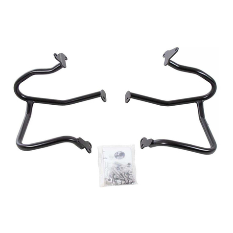
1x 700009487 Hauptständer
1x 700009488 Halter rechts
1x 700009489 Halter links
1x 700009490 Schraubensatz:
1x 700009487 Center stand
1x 700009488 Holder right
1x 700009489 Holder left
1x 700009490 Screw kit:
2x Linsenschraube M10x25
4x Zylinderschraube M10x12
2x Zylinderschraube M10x1,25x45
2x Zylinderschraube M10x1,25x40
2x Aludistanz Ø20xØ11x8,5
2x Aludistanz Ø20xØ11x3
4x U-Scheibe Ø10,5
2x Laufbuchse Stahl Ø28/Ø15x10,5x11
2x Schleifpin SW10x68xM8
1x Federsatz Typ 2
2x Filister head screw M10x25
4x Allen screw M10x12
2x Allen screw M10x1,25x45
2x Allen screw M10x1,25x40
2x Alu spacer Ø20xØ11x8,5
2x Alu spacer Ø20xØ11x3
4x Washer Ø10,5
2x Special steel spacer Ø28/Ø15x10,5x11
2x Grinding pin SW10x68xM8
1x Spring Set type 2
Hepco & Becker GmbH
An der Steinmauer 6
D-66955 Pirmasens
Germany
Tel.: +49 (0)6331 - 1453 - 100
Fax: +49 (0)6331 - 1453 - 120
eMail: vertrieb@hepco-becker.de
www.hepco-becker.de
Weiteres Zubehör auf unserer Homepage. More accessories: see our homepage.
2
5054560 00 01 / 5054537 00 01 / 5054554 00 01 / 5054568 00 01 / 5054571 00 01
WICHTIG
IMPORTANT
Die Schräglagenfreiheit ist eingeschränkt! Eine Seite nach der anderen montieren.
Alle beweglichen Teile einfetten. Schrauben mit Sicherungsmittel sichern
Die Voraussetzung für die Montage ist natürlich eine gewisse technische Erfahrung. Wenn Sie sich nicht sicher sind,wie
man eine bestimmte Arbeit ausführt, sollten Sie diese Ihrer Fachwerkstatt überlassen.
Ziehen sie alle zugänglichen Schrauben zuerst nur locker an. Nachdem alles montiert ist, werden die Schrauben dann auf
das entsprechende Anzugsmoment festgezogen. Dadurch wird sichergestellt, dass das Produkt spannungsfrei angebaut ist.
Anzugsmomente beachten! Nach der Montage alle Verschraubungen auf festen Sitz kontrollieren!
Inclination is limited. Mount one side after the other.
Grease all moving parts. Use liquid threadlocker to secure all screws and nuts.
Of course, the assembly requires a certain technical experience. If you are not sure how to execute a determined action,
you should ask your local distributor to do it. First, tighten all screws only loosely. After mounting all parts, the screws
should be tightened to the torque specified. This guarantees, that the product is mounted without tension. Observe
the tightening torques of the manufacturer! Control all screw connections after the assembling for tightness!
VORBEREITUNG
PREPARING
4x
2x
Die Original Schleifpins der Fußrasten rechts
und links entfernen und die mitgelieferten
Schleifpins SW10 montieren.
Change the original grinding pins at the
footrests left+right with the included longer
grinding pins SW10.
In die beiden Halter jeweils in die äußeren
Gewindebohrungen die Zylinderschrauben
M10x12 eindrehen.
Screw in the allen screws M10x12 into the
outer threaded holes in the holders.
BENÖTIGTE WERKZEUGE
TOOLS REQUIRED
Set Verlängerung/extension Ratsche/Ratchet
3
MONTAGEANLEITUNG
MOUNTING INSTRUCTIONS
1
2
2x
2x
2x
2x
2x
2x
Montage des rechten Halters:
Auf der rechten Seite die beiden Original-
schrauben hinter dem Fußbremshebel
entfernen, diese entfallen. Zur besseren Zu-
gänglichkeit die Fußrastenanlage demontieren.
Die Montage erfolgt an den nun freien Ge-
windebohrungen mit den Zylinderschrauben
M10x1,25x45 sowie U-Scheiben ø10,5.
Zwischen Halter und Rahmen die Aludistan-
zen Ø20xØ11x8,5 fügen.
Montage des linken Halters:
Links die beiden Schrauben des Seitenständers
lösen und diesen demontieren. Die beiden
Originalschrauben darunter entfernen, diese
entfallen.
Die Montage erfolgt an den nun
freien Gewindebohrungen mit den Zylinder-
schrauben M10x1,25x40 sowie U-Scheiben
Ø10,5. Zwischen Halter und Rahmen die
Aludistanzen Ø20xØ11x3 fügen.
Seitenständer wieder montieren.
Fastening of the right holder:
Remove the two original screws behind the
brake pedal, screws are obsolete.For better
accessibility, remove the footrest bracket.
Fastening of the holder with allen screws
M10x1,25x45 and washer Ø10,5 in the
now free threads. Add alu spacers
Ø20xØ11x8,5 between frame and holder.
Fastening of the left holder:
Loosen the two screws of the side stand on
the left side and disassemble it. Remove the
two original screws below, screws are
obsolete. Fastening of the holder with allen
screws M10x1,25x40 and washer Ø10,5
in the now free threads. Add alu spacers
Ø20xØ11x3 between frame and holder.
Mount side stand again.
Fahrtrichtung/driving direction
5054560 00 01 / 5054537 00 01 / 5054554 00 01 / 5054568 00 01 / 5054571 00 01
4
5054560 00 01 / 5054537 00 01 / 5054554 00 01 / 5054568 00 01 / 5054571 00 01
MONTAGEANLEITUNG
MOUNTING INSTRUCTIONS
3
4
1x
Montage des Hauptständers:
Jeweils rechts und links mit den Linsen-
schrauben M10x25 sowie den Laufbuchsen
ø28/ø15x10,5x11 in der mittleren Gewin-
debohrung der bereits montierten Halter
verschrauben.
Schraubensicherung verwenden.
Fastening of the side stand:
Fix it to the holder left and right with filister
head screws M10x25 and the special steel
spacers Ø28/Ø15x10,5x11 in the free
threads in the already mounted holders.
Use liquid threadlocker.
Montage der Feder:
Die Feder Typ 2 am Bolzen des Adapters
und am Bolzen des Hauptständers einhän-
gen.Der Ständer muss sich frei bewegen und
leicht nach oben klappen.
Wir empfehlen für die Montage das als
Zubehör erhältliche Federmontage-Werkzeug
(Art.-Nr.: 700030).
Fastening of the spring:
Mount spring to the existing holders on the
adapter and on the centre stand.
The stand must be freely moving and slightly
tilted upwards.
We recommend our spring-mounting kit
(item.-No.: 700030)
2x 2x
Fahrtrichtung/driving direction
FETT / GREASE
Fahrtrichtung/driving direction
ACHTUNG
CAUTION
Bitte kontrollieren Sie nun die Funktionalität Ihres Hauptständers und überprüfen Sie die Festigkeit aller montierten Teile.
Nehmen Sie das Motorrad vom Hauptständer und kontrollieren Sie den Hauptständer nach der Montage auf das selbst-
ständige Hochklappen in die obere Endlage. Die Kurvenfreiheit kann durch einen Hauptständer eingeschränkt werden.
Please now check the functionality of your center stand and check the strength of all assembled parts. Remove the motor-
cycle from the center stand and check the stand after assembly for automatic folding up to the upper end position. A center
stand may restrict the freedom to turn.

This manual suits for next models

4

Other hepco & becker Motorcycle Accessories manuals

hepco & becker 5036512 00 01 User manual

hepco & becker

hepco & becker 5036512 00 01 User manual

hepco & becker C-Bow 6306513 00 01 User manual

hepco & becker

hepco & becker C-Bow 6306513 00 01 User manual

hepco & becker 501221 00 01 User manual

hepco & becker

hepco & becker 501221 00 01 User manual

hepco & becker 611.793 00 02 Installation guide

hepco & becker

hepco & becker 611.793 00 02 Installation guide

hepco & becker 6704543 00 01 User manual

hepco & becker

hepco & becker 6704543 00 01 User manual

hepco & becker Sportrack 6709524 00 01 User manual

hepco & becker

hepco & becker Sportrack 6709524 00 01 User manual

hepco & becker 6604564 01 01 User manual

hepco & becker

hepco & becker 6604564 01 01 User manual

hepco & becker 6307546 00 01 User manual

hepco & becker

hepco & becker 6307546 00 01 User manual

hepco & becker 650774 01 02 chrom Installation guide

hepco & becker

hepco & becker 650774 01 02 chrom Installation guide

hepco & becker TANKRING LOCK-IT 5064551 00 01 User manual

hepco & becker

hepco & becker TANKRING LOCK-IT 5064551 00 01 User manual

hepco & becker 5017523 00 01 User manual

hepco & becker

hepco & becker 5017523 00 01 User manual

hepco & becker SPORTRACK 6707603 00 01 User manual

hepco & becker

hepco & becker SPORTRACK 6707603 00 01 User manual

hepco & becker 6264556 00 01 User manual

hepco & becker

hepco & becker 6264556 00 01 User manual

hepco & becker 42207568 00 01 User manual

hepco & becker

hepco & becker 42207568 00 01 User manual

hepco & becker 650434 01 01 User manual

hepco & becker

hepco & becker 650434 01 01 User manual

hepco & becker 6703531 00 01 User manual

hepco & becker

hepco & becker 6703531 00 01 User manual

hepco & becker 5012524 00 01 User manual

hepco & becker

hepco & becker 5012524 00 01 User manual

hepco & becker 740003 User manual

hepco & becker

hepco & becker 740003 User manual

hepco & becker 6607530 01 01 User manual

hepco & becker

hepco & becker 6607530 01 01 User manual

hepco & becker 5064564 00 01 User manual

hepco & becker

hepco & becker 5064564 00 01 User manual

hepco & becker Easyrack User manual

hepco & becker

hepco & becker Easyrack User manual
hepco & becker 6614559 01 05 User manual

hepco & becker

hepco & becker 6614559 01 05 User manual

hepco & becker 6607562 01 01 User manual

hepco & becker

hepco & becker 6607562 01 01 User manual

hepco & becker 5012538 00 01 User manual

hepco & becker

hepco & becker 5012538 00 01 User manual

Popular Motorcycle Accessories manuals by other brands

Rivco IC010-BP quick start guide

Rivco

Rivco IC010-BP quick start guide

Schubert F220 manual

Schubert

Schubert F220 manual

Fuelpak SOFTAIL 2012 instructions

Fuelpak

Fuelpak SOFTAIL 2012 instructions

Sena Momentum manual

Sena

Sena Momentum manual

DYNATEK Dyna 4000 Super Pro DP4000-1S User instructions

DYNATEK

DYNATEK Dyna 4000 Super Pro DP4000-1S User instructions

LAZER X6 owner's manual

LAZER

LAZER X6 owner's manual

SRC H-CB500X-14-01-SL manual

SRC

SRC H-CB500X-14-01-SL manual

DYNATEK DDK2-4 installation guide

DYNATEK

DYNATEK DDK2-4 installation guide

Pyle PLMCA60 user manual

Pyle

Pyle PLMCA60 user manual

Skully FENIX AR user manual

Skully

Skully FENIX AR user manual

3M Speedglas 9100 Series quick start guide

3M

3M Speedglas 9100 Series quick start guide

Thunderbike STEEL installation instructions

Thunderbike

Thunderbike STEEL installation instructions

Lincoln Electric VIKING 3350 Series Operator's manual

Lincoln Electric

Lincoln Electric VIKING 3350 Series Operator's manual

VMT F25E Mounting instructions

VMT

VMT F25E Mounting instructions

CATU MO-185 instruction manual

CATU

CATU MO-185 instruction manual

LegUp LandinGear Generation II installation manual

LegUp

LegUp LandinGear Generation II installation manual

Wolfman EX505 Mounting instructions

Wolfman

Wolfman EX505 Mounting instructions

Dakota Digital VHX systems operating manual

Dakota Digital

Dakota Digital VHX systems operating manual

manuals.online logo
manuals.online logoBrands
  • About & Mission
  • Contact us
  • Privacy Policy
  • Terms and Conditions

Copyright 2025 Manuals.Online. All Rights Reserved.