manuals.online logo
Brands
  1. Home
  2. •
  3. Brands
  4. •
  5. HIK VISION
  6. •
  7. Security Camera
  8. •
  9. HIK VISION DS-2CE11H0T-PIRL User manual

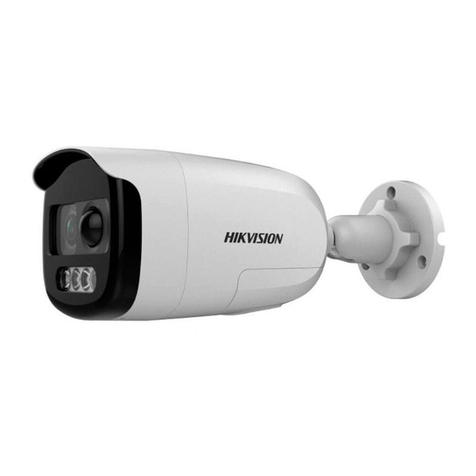
HIK VISION DS-2CE11H0T-PIRL User manual

UM D-2CE11H0T-PIRL  2018 Hikvision USA Inc.
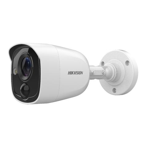
TurboHD
DS-2CE11H0T-PIRL
Bullet Camera
User Manua
Thank you for purchasing our product. If there are any questions, or requests, do
not hesitate to contact the dea er.
This manua may contain severa technica incorrect p aces or printing errors, and
the content is subject to change without notice. Updates wi be added to new
versions of this manua . We wi readi y improve or update the products or
procedures described in the manua .
UM D-2CE11H0T-PIRL  2018 Hikvision USA Inc.
1Regulatory Information
1.1 CC Information
P ease take attention that changes or modification not express y approved by the
party responsib e for comp iance cou d void the user’s authority to operate the
equipment.
CC Compliance: This equipment has been tested and found to comp y with the
imits for a C ass A digita device, pursuant to part 15 of the FCC Ru es. These imits
are designed to provide reasonab e protection against harmfu interference when
the equipment is operated in a commercia environment. This equipment
generates, uses, and can radiate radio frequency energy and, if not insta ed and
used in accordance with the instruction manua , may cause harmfu interference to
radio communications. Operation of this equipment in a residentia area is ike y to
cause harmfu interference in which case the user wi be required to correct the
interference at his own expense.
1.2 CC Conditions
This device comp ies with part 15 of the FCC Ru es. Operation is subject to the
fo owing two conditions:
1. This device may not cause harmfu interference.
2. This device must accept any interference received, inc uding interference that
may cause undesired operation.
1.3 EU Conformity Statement
This product and, if app icab e, the supp ied accessories too are marked
with “CE” and comp y therefore with the app icab e harmonized European
standards isted under the Low Vo tage Directive 2014/35/EU, the EMC Directive
2014/30/EU, the RoHS Directive 2011/65/EU.
2012/19/EU (WEEE Directive): Products marked with this symbo cannot
be disposed of as unsorted municipa waste in the European Union. For
proper recyc ing, return this product to your oca supp ier upon the
purchase of equiva ent new equipment, or dispose of it at designated
co ection points. For more information see: www.recyc ethis.info.
2006/66/EC (Battery Directive): This product contains a battery that
cannot be disposed of as unsorted municipa waste in the European
See the product documentation for specific battery information. The
battery is marked with this symbo , which may inc ude ettering to
indicate cadmium (Cd), ead (Pb), or mercury (Hg). For proper recyc ing, return the
battery to your supp ier or to a designated co ection point. For more information
see: www.recyc ethis.info.
1.4 Industry Canada ICES-003 Compliance
This device meets the CAN ICES-3 (A)/NMB-3(A) standards requirements.
1.5 Warning
This is a c ass A product. In a domestic environment this product may cause radio
interference in which case the user may be required to take adequate measures.
1.6 Safety Instruction
These instructions are intended to ensure that user can use the product correct y to
avoid danger or property oss.
The precaution measure is divided into “Warnings” and “Cautions.”
Warnings: Serious injury or death may occur if any of the warnings are neg ected.
Cautions: Injury or equipment damage may occur if any of the cautions are
neg ected.
UM D-2CE11H0T-PIRL  2018 Hikvision USA Inc.
Warnings
Fo ow
Cautions
Fo ow these
these safeguards to
precautions to prevent
prevent serious injury
potentia injury or
or death.
materia damage.
1.7 Warnings
•In the use of the device, you must be in strict comp iance with the e ectrica
safety regu ations of the nation and region.

•Input vo tage shou d meet both the SELV (Safety Extra Low Vo tage) and the
Limited Power Source with 12 VDC according to the IEC60950-1 standard. Refer
to technica specifications for detai ed information.
•Do not connect mu tip e devices to one power adapter to avoid overheating or
a fire hazard caused by over oad.
•Make sure that the p ug is firm y connected to the power socket.
•Make sure that the device is firm y fixed if wa mounting or cei ing mounting is
adopted.
•If smoke, odor, or noise rise from the device, turn off the power at once and
unp ug the power cord, and then contact the service center.
•Never attempt to disassemb e the camera by unprofessiona persona .

1.8 Cautions
•Do not drop the camera or subject it to physica shock.
•Do not touch sensor modu es with fingers.
•Do not p ace the camera in extreme y hot, co d (the operating temperature sha
be -40° to 60° C), dusty, or damp ocations, and do not expose it to high
e ectromagnetic radiation.
•If c eaning is necessary, use a c ean c oth with a bit of ethano and wipe it
gent y.
•Do not aim the camera at the sun or extra bright p aces.
•The sensor may be burned out by a aser beam, so when any aser equipment is
in use, make sure that the surface of the sensor wi not be exposed to the aser
beam.
•Do not expose the device to high e ectromagnetic radiation or extreme y hot,
co d, dusty, or damp environment.
•To avoid heat accumu ation, good venti ation is required for the operating
environment.

•Keep the camera away from iquid whi e in use for non-waterproof device.

•Whi e in de ivery, the camera sha be packed in its origina packing or packing of
the same texture.

1.9 Mark Description
Tab e 0-1 Mark Description
Mark Description
DC Vo tage
UM D-2CE11H0T-PIRL  2018 Hikvision USA Inc.
2Introduction
2.1 Product eatures
The main features are as fo ows:
•High performance CMOS sensor

•IR cut fi ter with auto switch
•OSD menu with configurab e parameters
•Auto white ba ance
•Interna synchronization
•SMART IR mode
•Visib e a arm
•PIR detection
•3-axis adjustment

2.2 Overview
2.2.1 Camera Overview
Figure 1, Camera Overview
3Installation
Before you start
•
Make sure that the device in the package is in good condition and a the
assemb y parts are inc uded.

•
Make sure that a the re ated equipment is powered off during the
insta ation.

•
Check the specification of the products for the insta ation environment.

•
Check whether the power supp y matches your power output to avoid
damage.

•
Make sure the wa is strong enough to withstand three times the weight
of the camera and the mount.

•
If the wa is cement, insert expansion bo ts before insta ing the camera. If
the wa is wood, use se f-tapping screws to secure the camera.

•
If the product does not function proper y, contact your dea er or the
nearest service center. Do NOT disassemb e the camera for repair or
maintenance yourse f.

3.1 Camera Installation
3.1.1 Ceiling/Wall Mounting without Junction Box
Steps:
1. Paste the dri temp ate (supp ied) to where you want to insta the
camera.
UM D-2CE11H0T-PIRL  2018 Hikvision USA Inc.
2. Dri the screw ho es and the cab e ho e (optiona ) in the
cei ing/wa according to the dri temp ate.
Figure 2, Dri Temp ate
Note:
Dri a cab e ho e when using the cei ing out et to route the cab e.
Figure 3, Fix the Camera to the Cei ing
3. Attach the bracket to the cei ing/wa , and secure the camera with
supp ied screws.
Note:
•
The supp ied screw package contains se f-tapping screws and
expansion bo ts.

•
For cement wa /cei ing, expansion bo ts are required to fix the
camera. For wood wa /cei ing, se f-tapping screws are required.

4. Route the cab es through the cab e ho e or the side opening.
5. Connect the corresponding power cord and video cab e.
6. Power on the camera to check whether the image on the monitor
is at an optimum ang e. If not, adjust the camera according to the
figure be ow to get an optimum ang e.
Figure 4, 3-axis Adjustment
1). Loosen the P screw to adjust the pan position [0° to 360°].
Tighten the screw after comp eting the adjustment.
UM D-2CE11H0T-PIRL  2018 Hikvision USA Inc.
2). Loosen the T screw to adjust the ti t position [0° to 180°].
Tighten the screw after comp eting the adjustment.
3). Loosen the R screw and rotate the camera [0° to 360°].
Tighten the screw after comp eting the adjustment.
3.1.2 Ceiling/Wall Mounting with Junction Box
Before you start:
You need to purchase a junction box separate y.
Steps:
1. Paste the dri temp ate on the cei ing/wa .
2. Dri screw ho es and the cab e ho e in the cei ing/wa according
to the ho es of the dri temp ate.
Figure 5, Dri Temp ate of Junction Box
3. Take apart the junction box and a ign the screw ho es of the bu et
camera with those on the junction box cover.
4. Fix the camera on the junction box’s cover with supp ied screws.
Figure 6, Fix the Camera on the Junction Box Cover
5. Attach the junction box body to the cei ing/wa by a igning the
screw ho es of the junction box.
6. Secure the junction box’s body with supp ied screws on the
cei ing/wa .
UM D-2CE11H0T-PIRL  2018 Hikvision USA Inc.
Figure 7, Fix the Junction Box to the Wa /Cei ing
7. Route the cab es through the bottom cab e ho e or the side cab e
ho e of the junction box.
8. Combine the junction box cover with its body.
Figure 8, Fix the Junction Box Cover back to its Body
9. Repeat step 5 and 6 of 2.1.1 Ceiling/Wall Mounting without
unction Box to comp ete the insta ation.
4Menu Description
Purpose:
Ca the menu by c icking the button on the PTZ Contro interface, or ca
the preset no.95.
Steps:
1. Connect the camera to the TVI DVR and the monitor, as shown be ow.
Figure 9, Connection
2. Power on the ana og camera, TVI DVR, and the monitor to view the image
on the monitor.
3. C ick PTZ Control to enter the PTZ Contro interface.
4. Ca the camera menu by c icking the button or ca the preset no. 95.
UM D-2CE11H0T-PIRL  2018 Hikvision USA Inc.
Figure 10, Main Menu Overview
5. C ick the direction arrow to contro the camera.
1). C ick Up/Down direction button to se ect the item.
2). C ick Iris+ to confirm the se ection.
3). C ick Left/Right direction button to adjust the va ue of the se ected
item.
4.1 VIDEO ORMAT
You can set the video format to 5 MP @ 20 fps, 4 MP @ 25 fps, 4 MP @ 30
fps, 2 MP @ 25 fps, or 2 MP @ 30 fps.
4.2 EXPOSURE
4.2.1 EXPOSURE MODE
You can set the EXPOSURE MODE to GLOBAL, BLC, or DWDR.
•GLOBAL



GLOBAL refers to the norma exposure mode, which adjusts ighting
distribution, variations, and non-standard processing.
•BLC (Backlight Compensation)
BLC (Back ight Compensation) compensates ight to the object in the
front to make it c ear, but this may cause overexposure of the
background where the ight is strong.
UM D-2CE11H0T-PIRL  2018 Hikvision USA Inc.
•DWDR (Digital Wide Dynamic Range)
The digita wide dynamic range he ps the camera provide c ear
images even under back ight circumstances. WDR ba ances the
brightness eve of the who e image and provides c ear images with
detai s.
4.2.2 AGC (Auto Gain Control)
It optimizes the c arity of the image in poor ight conditions. The AGC
eve can be set as HIGH, MEDIUM, or LOW. Se ect O to disab e the
AGC function.
Note:
The noise wi be amp ified when the AGC is on.
4.2.3 DAY/NIGHT
COLOR, B&W (B ack White), and AUTO are se ectab e for DAY and
NIGHT switches.
Note:
Under the LIGHTING mode, the image is in co or a the time, and
there’s no DAY/NIGHT setting in the menu.
•COLOR
The image is in co or in day mode a the time.
•B/W
The image is b ack and white a the time. Turning the IR LIGHT on in
poor ight conditions wi improve the image.
•AUTO
Figure 11, DAY NIGHT
You can turn on/off the IR LIGHT and set the SMART IR va ue in this
menu.
˗IR LIGHT
You can turn on/off the IR LIGHT to meet the circumstances.
˗SMART IR
The Smart IR function adjusts the ight to its most suitab e
intensity and prevents the image from overexposure. The SMART
IR va ue can be adjusted from 0 to 3. The greater the va ue, the
more obvious the effect.
•D-N THRESHOLD (Day to Night Threshold)
Day to Night Thresho d contro s the sensitivity of switching the day
mode to night mode. You can set the va ue from 1 to 9. The arger
the va ue, the more sensitive the camera.
•N-D THRESHOLD (Night to Day Threshold)
Night to Day Thresho d contro s the sensitivity of switching the night
mode to day mode. You can set the va ue from 1 to 9. The arger the
va ue, the more sensitive the camera.
UM D-2CE11H0T-PIRL  2018 Hikvision USA Inc.
4.3 VIDEO SETTINGS
Move the cursor to VIDEO SETTINGS and c ick Iris+ to enter the submenu.
CONTRAST, SHARPNESS, COLOR GAIN, 3 DNR, and MIRROR are adjustab e.
Figure 12, VIDEO SETTING
•WHITE BALANCE
White ba ance, the white rendition function of the camera, adjusts
the co or temperature according to the environment. It can remove
unrea istic co or casts in the image. You can set WHITE BALANCE
mode to AUTO or MANUAL.
˗
AUTO



Under AUTO mode, white ba ance is adjusted automatica y
according to the co or temperature of the scene i umination.
˗MANUAL
You can set the R-GAIN/B-GAIN va ue from 1 to 255 to adjust the
shades of red/b ue co or of the image.
Figure 13, MWB MODE
•BRIGHTNESS
Brightness refers to the brightness of the image. You can set the
brightness va ue from 1 to 9 to darken or brighten the image. The
greater the va ue, the brighter the image.
•CONTRAST
This feature enhances the difference in co or and ight between
parts of an image. You can set the CONTRAST va ue from 1 to 9.
•SHARPNESS
Sharpness determines the amount of detai the imaging system can
reproduce. You can set the SHARPNESS va ue from 1 to 9.
•SATURATION
Adjust this feature to change the saturation of the co or. The va ue
ranges from 1 to 9.
UM D-2CE11H0T-PIRL  2018 Hikvision USA Inc.
•DNR (Digital Noise Reduction)
The DNR function can decrease the noise effect, especia y when
capturing moving images in poor ight conditions, and de ivers more
accurate and sharper images. You can set the DNR va ue from 1 to
9.
•MIRROR
O , H, V, and HV are se ectab e for mirror.
O : The mirror function is disab ed.
H: The image f ips 180° horizonta y.
V: The image f ips 180° vertica y.
HV: The image f ips 180° both horizonta y and vertica y.
4.4 UNCTIONS
•WHITE LIGHT
The embedded white ight source can work as an visib e a arm or ighting.
In the WHITE LIGHT mode, you can set the mode to ALARM, LIGHTING, or
O .
When you set the WHITE LIGHT to ALARM, you can set the Parameters in
the TRIGGER MODE and the ALARM MODE to meet your needs.
˗TRIGGER MODE
>
DVR



Set the TRIGGER MODE to DVR. In this way, the a arm signa is sent
from the DVR and the camera works as the a arm detector in the
process. Besides, the a arm type on y supported by the DVR can a so
trigger the visib e a arm in the camera.
>CAMERA
Set the TRIGGER MODE to CAMERA, the embedded PIR modu e
sends the a arm signa to the visib e a arm in the camera when the
PIR modu e detects the a arm source.
˗ALARM
In the ALARM mode, you can set the ALARM MODE to SOLID or
LASHING.
Figure 14, ALARM MODE
>SOLID
Set the ALARM MODE to SOLID. In this way, the white ight source
turns on when the PIR modu e receives the a arm signa .
In the TIME SETTING you can set the time to 5s, 10s, 15s, 30s, or
60s, which means that the so id mode stays for the set time when
the camera receives one a arm signa .
Note:
The so id mode wi stay for another set time when a second a arm
signa is received, and the rest can be done in the same way.
>LASHING
Set the ALARM MODE to LASHING. In this way, the white ight
source f ashes when the PIR modu e receives the a arm signa .
UM D-2CE11H0T-PIRL  2018 Hikvision USA Inc.
•LIGHTING
Se ect the LIGHTING mode, the embedded white ight source turns on in
poor ight conditions automatica y. You can set the LIGHTING MODE to
SOLID or LASHING.
˗SOLID
The white ight source turns on in poor ighting conditions.
Figure 15, SOLID
˗LASHING
When you set the LIGHTING MODE to LASHING, you can set the
TRIGGER MODE to CAMERA or DVR.
The white ight source f ashes in poor ighting conditions when
receiving the a arm signa .
*
TRIGGER MODE
o
DVR



Set the TRIGGER MODE to DVR. In this way, the a arm signa is
sent from the DVR, and the camera works as an a arm detector
in the process. Besides, the a arm type on y supported by the
DVR can a so trigger the visib e a arm in the camera.
Figure 16, FLASHING
oCAMERA
Set the TRIGGER MODE to CAMERA, the embedded PIR modu e
sends the a arm signa to the visib e a arm in the camera when
the PIR modu e detects the a arm source.
˗O
Se ect O to disab e this function.
•PIR LEVEL
Adjust the sensitivity of the PIR modu e. The higher the va ue, the more
sensitive the PIR modu e.
•ACTORY DE AULT
Reset a the settings to the factory defau ts.
UM D-2CE11H0T-PIRL  2018 Hikvision USA Inc.
•EXIT
Move the cursor to EXIT and c ick Iris+ to exit the menu.
•SAVE & EXIT
Move the cursor to SAVE & EXIT and c ick Iris+ to save the settings and
exit the menu.

Other HIK VISION Security Camera manuals

HIK VISION DS-2CE16D(F)7T-IT3Z User manual

HIK VISION

HIK VISION DS-2CE16D(F)7T-IT3Z User manual

HIK VISION DS-2CE11D8T-PIRL User manual

HIK VISION

HIK VISION DS-2CE11D8T-PIRL User manual

HIK VISION DS-2CE16D8T-AIT3ZE User manual

HIK VISION

HIK VISION DS-2CE16D8T-AIT3ZE User manual

HIK VISION DS-2CE11D0T-PIRL User manual

HIK VISION

HIK VISION DS-2CE11D0T-PIRL User manual

HIK VISION NETWORK CAMERA User manual

HIK VISION

HIK VISION NETWORK CAMERA User manual

HIK VISION THC-B129-P User manual

HIK VISION

HIK VISION THC-B129-P User manual

HIK VISION DS-2DE2C200MWG-E User manual

HIK VISION

HIK VISION DS-2DE2C200MWG-E User manual

HIK VISION HiLook IPC-B149H User manual

HIK VISION

HIK VISION HiLook IPC-B149H User manual

HIK VISION DS-2TD2 Series User manual

HIK VISION

HIK VISION DS-2TD2 Series User manual

HIK VISION DS-2CD4312F-I User guide

HIK VISION

HIK VISION DS-2CD4312F-I User guide

HIK VISION DS-MH2211 User manual

HIK VISION

HIK VISION DS-MH2211 User manual

HIK VISION NETWORK CAMERA User manual

HIK VISION

HIK VISION NETWORK CAMERA User manual

HIK VISION DS-2DF1-57XY User manual

HIK VISION

HIK VISION DS-2DF1-57XY User manual

HIK VISION DS-2CE12KF3T-PIRXO User manual

HIK VISION

HIK VISION DS-2CE12KF3T-PIRXO User manual

HIK VISION DS-2CD51C5G0-IZS User manual

HIK VISION

HIK VISION DS-2CD51C5G0-IZS User manual

HIK VISION DS-2CE12DFT-PIRXOF28 User manual

HIK VISION

HIK VISION DS-2CE12DFT-PIRXOF28 User manual

HIK VISION UD04334B User manual

HIK VISION

HIK VISION UD04334B User manual

HIK VISION DS-2AE7232TI-A User manual

HIK VISION

HIK VISION DS-2AE7232TI-A User manual

HIK VISION DS-2CC11A1P User manual

HIK VISION

HIK VISION DS-2CC11A1P User manual

HIK VISION D8T Series User manual

HIK VISION

HIK VISION D8T Series User manual

HIK VISION PanoVu Series User manual

HIK VISION

HIK VISION PanoVu Series User manual

HIK VISION DS-2CC5173N-VP IR User manual

HIK VISION

HIK VISION DS-2CC5173N-VP IR User manual

HIK VISION DS-2XM6522G0-IM/ND User manual

HIK VISION

HIK VISION DS-2XM6522G0-IM/ND User manual

HIK VISION HWI-D720H-V/-Z User manual

HIK VISION

HIK VISION HWI-D720H-V/-Z User manual

Popular Security Camera manuals by other brands

LG LNV5100 owner's manual

LG

LG LNV5100 owner's manual

Huviron SK-N611 quick guide

Huviron

Huviron SK-N611 quick guide

Bosch NBN-63023-B Quick installation guide

Bosch

Bosch NBN-63023-B Quick installation guide

Smartwares CS89C quick start guide

Smartwares

Smartwares CS89C quick start guide

D-Link DCS-2630L Setting up

D-Link

D-Link DCS-2630L Setting up

ETS AVN806 Operation guide

ETS

ETS AVN806 Operation guide

Digimerge DPV34D instruction manual

Digimerge

Digimerge DPV34D instruction manual

Veho CAVE VHS-002-IPC quick start guide

Veho

Veho CAVE VHS-002-IPC quick start guide

Commax DRC-4FC user manual

Commax

Commax DRC-4FC user manual

Samcon ExCam IPM1145 user manual

Samcon

Samcon ExCam IPM1145 user manual

Idis DirectIP DC-S Series installation manual

Idis

Idis DirectIP DC-S Series installation manual

ALIBI ALI-NS1008HDMI Quick installation guide

ALIBI

ALIBI ALI-NS1008HDMI Quick installation guide

Arlo Pro 4 quick start guide

Arlo

Arlo Pro 4 quick start guide

Novus NVIP-4H-6532M/F user manual

Novus

Novus NVIP-4H-6532M/F user manual

Wiseup T183 user guide

Wiseup

Wiseup T183 user guide

dallmeier MDF4220HD Commissioning

dallmeier

dallmeier MDF4220HD Commissioning

deXlan MPEG4 user manual

deXlan

deXlan MPEG4 user manual

NST HK-CD6IP-6 user manual

NST

NST HK-CD6IP-6 user manual

manuals.online logo
manuals.online logoBrands
  • About & Mission
  • Contact us
  • Privacy Policy
  • Terms and Conditions

Copyright 2025 Manuals.Online. All Rights Reserved.