Hilti TE 706-AVR User manual

TE 706 /
TE 706-AVR
Bedienungsanleitung de
Operating instructions en
Mode d’emploi fr
Istruzioni d’uso it
Gebruiksaanwijzing nl
Manual de instruções pt
Manual de instrucciones es
Brugsanvisning da
Käyttöohje fi
Bruksanvisning no
Bruksanvisning sv
Οδηγιες χρησεως
el
Kasutusjuhend et
Lietoßanas pamåcîba lv
Instrukcija lt

5
1
7
3
4
2
8
9
10
11
6
1

1
2
6
4
5
10
82
3
7
9
1
3
2,4
1
3
2
1
2
1
2 3
4 5
6 7

11
en
It is essential that the operating instructions
are read before the tool is operated for the
first time.
Always keep these operating instructions
together with the tool.
Ensure that the operating instructions are
with the tool when it is given to other
persons.
TE 706/TE 706-AVR breaker
1. General information
1.1 Safety notices and their meaning
-CAUTION-
Draws attention to a potentially dangerous situation that
could lead to minor personal injury or damage to the
equipment or other property.
-NOTE-
Draws attention to instructions and other useful infor-
mation.
1.2 Pictograms
Contents Page
1. General information 11
2. Description 12
3. Tools and accessories 12
4. Technical data 13
5. Safety rules 13
6. Before use 15
7. Operation 15
8. Care and maintenance 16
9. Troubleshooting 17
10. Disposal 18
11. Manufacturer’s warranty – tools 18
12. EC declaration of conformity 19
Operating controls and parts
Chuck
Chisel adjustment and locking switch
On/off switch
Grip
Supply cord
Screw knob
Side handle
Lock symbol
Power level selection switch
Theft protection indicator (option)
Service indicator
These numbers refer to the corresponding illustra-
tions. The illustrations can be found on the fold-out cover
pages. Keep these pages open while studying the oper-
ating instructions.
In these operating instructions, the TE 706 and / or
TE 706-AVR breaker is referred to as “ the power tool”.
Location of identification data on the power tool.
The type designation can be found on the rating plate
and the serial number on the side of the motor housing.
Make a note of this data in your operating instructions
and always refer to it when making an enquiry to your
Hilti representative or service department.
Type:
Serial No.:
Warning signs
Symbols
General
warning Warning:
electricity Warning:
hot surface
Read the
operating
instructions
before use.
Return waste
material for
recycling
Lock-
symbol
Equipped with
theft protection
system

12
en
2. Description
2.1 Use of the power tool as intended
The power tool is designed for medium-duty chiseling
work. It is suitable for breaking/removing and demol-
ishing concrete, masonry, stone or asphalt. It is intended
for use on construction sites of all kinds.
The power tool may be operated only when connected
to a power supply providing a voltage and frequency in
compliance with the information given on its rating plate.
Changes or modifications to the power tool are not per-
missible.
2.2 Important features of the power tool
2.2.1 Active vibration reduction
●The TE 706-AVR is equipped with an active vibration
reduction system which cuts vibration to 40% of that
of the TE 706 (without Active Vibration Reduction).
2.2.2 Theft protection system (option)
●The power tool may be equipped with the optional
theft protection system. If the power tool is equipped
with this feature, it can be activated and made ready
for operation only by way of the corresponding acti-
vation key.
2.2.3 Chuck
●TE-Y (SDSmax) quick-change chuck
2.2.4 Switch
●On/off switch
●3-position power level selection switch (100%, 75%,
50%)
●Chisel adjustment and locking switch (for 24 click-
stop positions per revolution)
3. Tools and accessories
TE 706/TE 706-AVR
TE-Y chuck (SDSmax)
Pointed chisel
Flat chisel
Wide-flat chisel
Hollow chisel
Channel chisel
Mortar chisel
Flexible chisel
Bushing tool
Tamping tool
Earth rod rammer
TPS Theft Protection System with Company
Card, Company Remote and TPS-K activation key
Use the Hilti tools listed above. With these tools you will achieve a higher breaking and material removal
performance and longer service life as the power tool and the insert tool have been optimized as a system.
2.2.5 Grip (with soft synthetic rubber padding)
●Two-way adjustable (pivoting) and vibration-absorb-
ing side handle
●Vibration absorbing grip
2.2.6 Safety features
●Electronic interlock to prevent unintentional restart-
ing after interruption of the power supply (see sec-
tion 9.).
●Casing and grip isolated from interior parts of the tool
to reduce transmission of heat and vibration.
●Automatic electronic overheating and overvoltage cut-
out (see section 9.).
2.2.7 Lubrication
●Permanent lubrication with separate lubrication cham-
bers for the gearing section and hammering mecha-
nism.
2.2.8 Indicator lamps
●Service indicator lamp (red, see section 8.3).
●Theft protection system indicator (available as an
option) (yellow, see section 7.2.1).
2.2.9 Items supplied as standard
●Power tool
●Side handle
●Grease dispenser, 50 ml
●Cleaning cloth
●Operating instructions
●Toolbox complete with overview of the insert tools
(chisels) available.
Width (mm)
– –
26
50–120
28
22–36
38
150
40 x 40
150 x 150
∅15–25
option
Length (mm)
280–700
280–700
280–500
280
280
280
650
250
300
300
Width (in)
– –
3/4″
2″–41/2″
1″
7/8″–11/2″
15/16″
57/8″
57/8″
– –
– –
Length (in)
11″–27″
11″–27″
11″–19″
11″
11″
11″
251/2″
10″
– –
– –

13
en
5. Safety rules
5.1 General safety rules
-WARNING- Read all instructions! Failure to follow all
instructions listed below may result in electric shock,
fire and/or serious injury. The term "power tool" in all of
the warnings listed below refers to your mains operated
(corded) power tool or battery operated (cordless) power
tool.
SAVE THESE INSTRUCTIONS
5.1.1 Work area
a) Keep the work area clean and well lit. Cluttered and
dark areas invite accidents.
b) Do not operate power tools in explosive atmos-
pheres, such as in the presence of flammable liq-
uids, gases or dust. Power tools create sparks which
may ignite the dust or fumes.
c)Keep children and bystanders away while operat-
ing a power tool. Distractions can cause you to lose
control.
5.1.2 Electrical safety
a) Power tool plugs must match the outlet. Never mod-
ify the plug in any way. Do not use any adapter plugs
with earthed (grounded) power tools.
Unmodified plugs and matching outlets will reduce
risk of electric shock.
b) Avoid body contact with earthed or grounded sur-
faces such as pipes, radiators, ranges and refrig-
erators. There is an increased risk of electric shock
if your body is earthed or grounded.
c) Do not expose power tools to rain or wet conditions.
Water entering a power tool will increase the risk of
electric shock.
d) Do not abuse the cord. Never use the cord for car-
rying, pulling or unplugging the power tool. Keep
cord away from heat, oil, sharp edges or moving
parts. Damaged or entangled cords increase the risk
of electric shock.
e) When operating a power tool outdoors, use an exten-
sion cord approved for outdoor use. Use of a cord
suitable for outdoor use reduces the risk of electric
shock.
5.1.3 Personal safety
a) Stay alert, watch what you are doing and use com-
mon sense when operating a power tool. Do not use
a power tool while you are tired or under the influ-
ence of drugs, alcohol or medication. A moment of
inattention while operating power tools may result in
serious personal injury.
4. Technical data
Power tool TE 706/TE 706-AVR
Rated power input
Rated voltage
Rated current
Mains frequency 50–60 Hz
Weight of tool 7.2 kg
Dimensions (L
×
W
×
H) 560
×
125
×
250 mm
Chuck TE-Y (SDSmax)
Hammering speed under load 2760 blows/min
Single impact energy 6–10 joules
Chiseling performance in medium-hard
concrete 750 cm3/min
Double insulated (in accordance with
EN 60745) Protection class II Z
Interference immunity In accordance with EN 55014-2
Radio and television interference suppression In accordance with EN 55014-1
●Typical A-weighted sound power TE 706 101 dB (A)
level: TE 706-AVR 98 dB (A)
●Typical A-weighted sound pressure TE 706 90 dB (A)
level: TE 706-AVR 87 dB (A)
Wear ear protection!
For the given sound power level as per
EN 60745, the tolerance is 3 dB.
●Typical weighted vibration at the grip: TE 706 13 m/s2
TE 706-AVR 5 m/s2
Right of technical changes reserved.
1200 W
100 V
12.3 A
1200 W
110 V
11.1 A
1180 W
120 V
9.9 A
1200 W
220 V
9.0 A
1200 W
230 V
8.7 A
1200 W
240 V
8.6 A

14
b) Use safety equipment. Always wear eye protection.
Safety equipment such as dust mask, non-skid safety
shoes, hard hat, or hearing protection used for appro-
priate conditions will reduce personal injuries.
c) Avoid accidental starting. Ensure the switch is in
the off position before plugging in. Carrying power
tools with your finger on the switch or plugging in
power tools that have the switch on invites accidents.
d) Remove any adjusting key or wrench before turn-
ing the power tool on. A wrench or a key left attached
to a rotating part of the power tool may result in per-
sonal injury.
e) Do not overreach. Keep proper footing and balance
at all times. This enables better control of the power
tool in unexpected situations.
f) Dress properly. Do not wear loose clothing or jew-
ellery. Keep your hair, clothing and gloves away
from moving parts. Loose clothes, jewellery or long
hair can be caught in moving parts.
g) If devices are provided for the connection of dust
extraction and collection facilities, ensure these
are connected and properly used. Use of these devices
can reduce dust related hazards.
5.1.4 Power tool use and care
a) Do not force the power tool. Use the correct power
tool for your application. The correct power tool will
do the job better and safer at the rate for which it was
designed.
b) Do not use the power tool if the switch does not turn
it on and off. Any power tool that cannot be controlled
with the switch is dangerous and must be repaired.
c) Disconnect the plug from the power source before
making any adjustments, changing accessories, or
storing power tools. Such preventive safety mea-
sures reduce the risk of starting the power tool acci-
dentally.
d) Store idle power tools out of the reach of children
and do not allow persons unfamiliar with the power
tool or these instructions to operate the power tool.
Power tools are dangerous in the hands of untrained
users.
e) Maintain power tools. Check for misalignment or
binding of moving parts, breakage of parts and any
other condition that may affect the power tool's oper-
ation. If damaged, have the power tool repaired
before use. Many accidents are caused by poorly
maintained power tools.
f) Keep cutting tools sharp and clean. Properly main-
tained cutting tools with sharp cutting edges are less
likely to bind and are easier to control.
g) Use the power tool, accessories and tool bits etc.,
in accordance with these instructions and in the
manner intended for the particular type of power
tool, taking into account the working conditions and
the work to be performed. Use of the power tool for
operations different from those intended could result
in a hazardous situation.
5.1.5 Service
a) Have your power tool serviced by a qualified repair
person using only genuine replacement parts. This
will ensure that the safety of the power tool is main-
tained.
5.2 Additional safety precautions
5.2.1 Personal safety
a) Wear ear protection. Excessive noise may lead to a
loss of hearing.
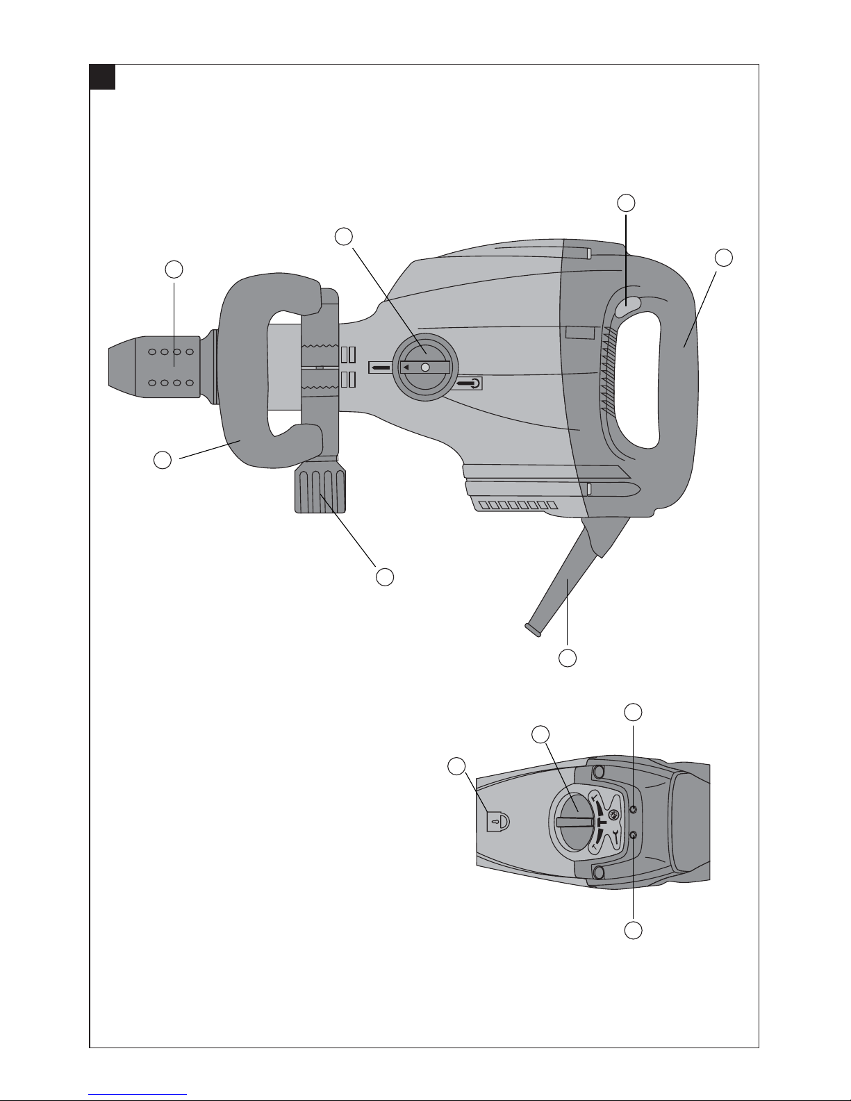
b) Use the auxiliary handle supplied with the tool.
Loss of control of the tool may lead to injury.
c) Breathing protection must be worn when the tool is
used without a dust removal system for work that
creates dust.
d) To avoid tripping and falling when working, always
lead the sypply cord, extension cord and dust extrac-
tion hose away tho the rear.
5.2.2 Electrical safety
a) Before beginning work, check the working area (e.g.
with a metal detector) to ensure that no concealed
electric cables or gas and water pipes are present.
External metal parts of the tool may become live if,
for example, an electric cable is damaged inadvertenly.
This presents a serious risk of electric shock.
b) Check the condition of the supply cord and its plug
connections and have it replaced by a qualified elec-
trician if damage is found. Check the condition of
the extension cord and replace it if damage is found.
Do not touch the supply in the event of it suffering
damage while working. Disconnect the supply cord
plug from the socket. Damaged supply cords and
extension cords present a risk of electric shock.
5.2.3 Work area
a) Ensure that the workplace is well lit.
b) Ensure that the workplace is well ventilated.
Poorly ventilated workplaces may be injurious to the
health due to exposeure to dust.
5.2.4 Personal protective equipment
The user and any other persons in the vicinity must
wear suitable eye protection, a hard hat, ear protection
and protective gloves when the tool is in use. Breath-
ing protection must be worn if no dust removal sys-
tem is used.
The general safety precautions for power tools contain
all product-specific precautions for the power tool
described in these operating instructions. The precau-
tions listed under (5.1.3 c, d, f, g) are not relevant to this
power tool.
en
Wear ear
protection Wear
protective
gloves
Wear
breathing
protection
Wear eye
protection Wear a
hard hat

15
en
6. Before use
Ensure that the tool is not yet connected to the electric
supply.
6.1 Fitting the side handle
1. Position the side handle on the tool.
2. Secure the side handle by tightening the screw knob.
6.2 Use of extension cords
Use only extension cords of a type approved for the
application and with conductors of adequate cross sec-
tion.
Recommended minimum conductor cross section and
max. cable lengths:
Mains voltage Conductor cross section AWG
1.5 mm22.0 mm22.5 mm23.5 mm214 12
100 V – 20 m – 30 m – –
110–120 V 20 m 25 m 30 m – 75 ft 125 ft
220–240 V 50 m – 100 m – – –
Do not use extension cords with 1.25 mm2or 16 AWG
conductor cross sections.
6.3 Use of a generator or transformer
This tool may be powered by a generator or transformer
which fulfils the following conditions:
– AC voltage output, power output at least 2600 W.
– The operating voltage must be within +5% and –15 %
of the rated voltage at all times.
– Frequency range 50–60 Hz, never above 65 Hz.
– Automatic voltage regulation with starting boost.
Never operate other tools or appliances from the gen-
erator or transformer at the same time. Switching other
tools or appliances on and off can cause undervoltage
and/or overvoltage peaks which may cause damage to
the power tool.
7.1.2.2 Locking the insert tool
9. Turn the chisel adjustment and locking switch to the
"Lock chisel" position.
10. Rotate the chisel until it engages (24 click-stop posi-
tions per revolution).
7.1.3 Removing the insert tool
-CAUTION-
– The insert tool may become hot during use. There is
a risk of burning the hands. Wear protective gloves
when changing insert tools.1. Unplug the supply cord
form the power source.
2. Open the chuck by pulling back the chuck release
sleeve.
3. Pull the insert tool out of the chuck.
7.1.4 Setting the chiseling power level
Chiseling power can be set to one of three positions
(50%, 100 % und 75%) by turning the power level selec-
tor switch.
7. Operation
7.1 Preparation for operation
7.1.1 Adjusting the position of the side handle
1. Unplug the supply cord form the power source.
2. Release the screw knob on the side handle.
3. Bring the side handle into the desired position.
4. Secure the side handle in the desired position by tight-
ening the screw knob.
7.1.2 Fitting the insert tool
1. Unplug the supply cord form the power source.
2. Check that the connection end of the insert tool is
clean and lightly greased. Clean it and grease it if
necessary.
3. Check that the sealing lip of the dust shield is clean
and in good condition. Clean the dust shield if nec-
essary or replace it if the sealing lip is damaged. (See
section 8.)
4. Push the insert tool into the chuck and rotate it while
applying slight pressure until it engages in the guide
grooves.
5. Push the insert tool further into the chuck until it is
heard to engage.
6. Check that the insert tool has engaged correctly by
pulling on it.
7.1.2.1 Positioning the insert tool
7. Turn the chisel adjustment and locking switch to the
"Rotate chisel" position.
8. Rotate the chisel to the desired position.

16
7.2 Operation
7.2.1 Activating the power tool (theft protection
system)
(Optional – not available with all versions.)
Further detailed information about activation and use of
this optional feature can be found in the separate oper-
ating instructions for the theft protection system.
1. Plug the supply cord into the power outlet. The yel-
low theft protection indicator lamp blinks. The power
tool is now ready to receive the signal from the acti-
vation key.
2. Hold the activation key close to the lock symbol. The
power tool is activated as soon as the theft protection
indicator lamp no longer lights.
-NOTE-
In the event of interruption of the electric supply to the
power tool, e.g. brief disconnection to move to a differ-
ent workplace, the power tool remains operational for
approx. 20 minutes. After a longer interruption, the power
tool must be reactivated by way of the activation key.
en
8. Care and maintenance
Unplug the supply cord form the power source.
8.1 Care of insert tools
Clean off dirt and dust deposits adhering to the insert
tools and protect them from corrosion by wiping the
insert tools from time to time with an oil-soaked rag.
Hilti polygon chisels require no resharpening.
8.2 Care of the power tool
The outer casing of the tool is made from impact-resis-
tant plastic. Sections of the grip are made from a syn-
thetic rubber material.
Never operate the power tool when the ventilation slots
are blocked. Clean the ventilation slots carefully using
a dry brush. Do not permit foreign objects to enter the
interior of the power tool. Clean the outside of the power
tool at regular intervals using a slightly damp cloth. Do
not use a spray, steam pressure cleaning equipment or
running water for cleaning. This may negatively affect
the electrical safety of the power tool. Always keep the
grip surfaces of the power tool free from oil and grease.
Do not use cleaning agents which contain silicone.
8.3 Service indicator
The power tool is equipped with a service indicator.
8.3.1 The indicator lamp lights red
The power tool has been in use for a predetermined time
and now requires servicing.
After the lamp lights for the first time, the power tool
may continue to be used for approx. 10 days before the
automatic cut-out is activated. Bring the power tool to
a Hilti service center in good time so that the tool is
always ready for use when required.
8.3.2 The indicator lamp blinks red
A fault has occurred.
The power tool has been rendered inoperable. Return
the power tool to a Hilti service center for repair.
8.3.3 Protective cut-out
The power tool is equipped with an overheating pre-
vention cut-out. This cut-out may be activated without
any warning. The cut-out may also be activated (or the
power tool may refuse to start), without the indicator
lighting, if a fault in the electric supply is detected (see
section 9).
8.4 Maintenance
Check all external parts of the tool for damage at regu-
lar intervals and check that all controls operate fault-
lessly. Do not operate the tool if parts are damaged or
when the controls do not function faultlessly. If neces-
sary, your power tool should be repaired at a Hilti repair
center.
Repairs to the electrical section of the tool may be car-
ried out only by trained electrical specialists.
7.2.2 Chiseling
–The power tool and the chiseling operation emit noise.
Excessive noise may damage the hearing. Wear ear
protection.
–Chiseling may cause splintering of the material. Splin-
ters may cause injury to parts of the body and eyes.
Wear eye protection, protective gloves and breath-
ing protection if no dust removal system is used.
-NOTE-
Working at low temperatures:
The hammering mechanism works only when the tool
has reached a minimum operating temperature.
Bring the drill bit into contact with the base material and
allow the tool to run under no load until the minimum
operating temperature is reached. If necessary, repeat
this procedure until the hammering mechanism begins
to operate.
7.2.2.1 Switching on
1. Plug the supply cord into the power outlet.
2. Press the on/off switch.
7.2.2.2 Switching off
1. Press the on/off switch.

en
17
9. Troubleshooting
If the fault cannot be remedied by the measures listed above, the power tool should be checked at a Hilti
service center.
Fault
The power tool doesn't
start.
The power tool doesn't
start and the indicator
lamp blinks yellow.
The power tool doesn't
start and the indicator
lamp blinks red.
The power tool doesn't
start or cuts out during
operation.
No hammering action.
The tool does not achieve
full power.
Possible cause
The electronics are being initialized
(this takes up to approx. 4 seconds
after the supply cord is plugged in)
or the electronic cut-out has been
activated after an interruption in the
electric supply.
There is an interruption in the electric
supply.
The supply cord or plug is defective.
Generator with sleep mode.
The power tool has not been activated
(tools with optional theft protection
system).
A fault has occurred in the tool.
The overheating prevention cut-out
has been activated.
Unstable electric supply (under- or
overvoltage cut-out activated).
The extension cord is too long or has
an inadequate cross section.
The power tool is too cold.
A fault has occurred in the tool.
The power level selector switch is not
in the full power position.
The extension cord is too long or has
an inadequate cross section.
The voltage provided by the electric
supply is too low.
Remedy
Switch the tool off and on again.
Check the electric supply, for example,
by plugging in and starting another
appliance.
Have the supply cord and plug checked
by an electrical specialist and replaced if
necessary.
Apply a load to the generator by connect-
ing another appliance (e.g. a lamp) and
then switch the power tool off and on
again.
Use the activation key to activate the
power tool.
The power tool should be repaired at a
Hilti service center.
Allow the tool to cool down. Clean the
ventilation slots (see section 8.2).
Disconnect other appliances connected
to the same power source or connect the
power tool to a different power source.
Use an extension cord of permissible
length and of adequate cross section
(see 6.2).
Allow the tool to warm up to the minimum
operating temperature (see 7.2.2).
The power tool should be repaired at a
Hilti service center.
Bring the power level selector switch to
the correct position.
Use an extension cord of permissible
length and of adequate cross section
(see 6.2).
Connect the tool to a different power
source.

18
en
11. Manufacturer’s warranty – tools
Hilti warrants that the tool supplied is free of defects
in material and workmanship. This warranty is valid so
long as the tool is operated and handled correctly,
cleaned and serviced properly and in accordance with
the Hilti Operating Instructions, and the technical sys-
tem is maintained. This means that only original Hilti
consumables, components and spare parts may be
used in the tool.
This warranty provides the free-of-charge repair or
replacement of defective parts only over the entire lifes-
pan of the tool. Parts requiring repair or replacement
as a result of normal wear and tear are not covered by
this warranty.
Additional claims are excluded, unless stringent
national rules prohibit such exclusion. In particular,
Hilti is not obligated for direct, indirect, incidental
or consequential damages, losses or expenses in
connection with, or by reason of, the use of, or inabil-
ity to use the tool for any purpose. Implied warranties
of merchantability or fitness for a particular purpose
are specifically excluded.
For repair or replacement, send tool or related parts
immediately upon discovery of the defect to the address
of the local Hilti marketing organization provided.
This constitutes Hilti's entire obligation with regard to
warranty and supersedes all prior or contemporane-
ous comments and oral or written agreements con-
10. Disposal
Most of the materials from which Hilti power tools are manufactured can be recycled. The materials must be cor-
rectly separated before they can be recycled. In many countries, Hilti has already made arrangements for taking
back your old power tools for recycling. Please ask your Hilti customer service department or Hilti representative
for further information.
Only for EU countries
Do not dispose of electric tools together with household waste material!
In observance of European Directive 2002/96/EC on waste electrical and electronic equipment
and its implementation in accordance with national law, electric tools that have reached the
end of their life must be collected separately and returned to an environmentally compatible
recycling facility.

19
en
12. EC declaration of conformity
We declare, on our sole responsibility, that this product
complies with the following standards or standardiza-
tion documents: 89/336/EEC, 98/37/EC, 2000/14/EC,
EN 55014-1, EN 55014-2, EN 60745-1, EN 60745-2-6,
EN 61000-3-2, EN 61000-3-3
We declare, on our sole responsibility, that this product
complies with the following standards or standardiza-
tion documents: 89/336/EEC, 98/37/EC, 2000/14/EC,
EN 55014-1, EN 55014-2, EN 60745-1, EN 60745-2-6,
EN 61000-3-2, EN 61000-3-3
Designation: Breaker
Type: TE 706
Year of design: 2004
Measured sound power level
LWA:100 dB/1pW
Guaranteed sound power level
LWAd:102 dB/1pW
Conformity assessment procedure: 2000/14/EC
Annex VI
European TÜV NORD CERT,
Notified Body: Am TÜV 1, 30519 Hannover,
Germany
European file number: CE 0032 - 310 05 001 6 001
Designation: Breaker
Type: TE 706-AVR
Year of design: 2004
Measured sound power level
LWA:97 dB/1pW
Guaranteed sound power level
LWAd:101 dB/1pW
Conformity assessment procedure: 2000/14/EC
Annex VI
European TÜV NORD CERT,
Notified Body: Am TÜV 1, 30519 Hannover,
Germany
European file number: CE 0032 - 310 05 002 6 001
Hilti Corporation
Peter Cavada Dr. Heinz-Joachim Schneider
Head Process & Quality Management Executive Vice President
Business Area Business Area
Electric Tools & Accessories Electric Tools & Accessories
10/2004 10/2004
Hilti Corporation
Peter Cavada Dr. Heinz-Joachim Schneider
Head Process & Quality Management Executive Vice President
Business Area Business Area
Electric Tools & Accessories Electric Tools & Accessories
10/2004 10/2004

Hilti Corporation
LI-9494 Schaan
Tel.: +423 / 234 2111
Fax: +423 / 234 29 65
www.hilti.com
Hilti = registered trademark of Hilti Corp., Schaan W 3031 0406 10-Pos.1 1 Printed in Liechtenstein © 2006
Right of technical and programme changes reserved S. E. & O. 282211 / D
*282211*
282211
This manual suits for next models
1
Table of contents
Other Hilti Power Tools manuals

Hilti
Hilti TE 1000-AVR User manual

Hilti
Hilti SF 144-A User manual

Hilti
Hilti SD 4500-A22 User manual

Hilti
Hilti DX 9-HSN User manual

Hilti
Hilti DD 160 User manual

Hilti
Hilti TE 700-AVR User manual

Hilti
Hilti TE 500-A36 User manual

Hilti
Hilti WSJ 750-ET User manual

Hilti
Hilti WSC 70-A36 User manual

Hilti
Hilti GX 3 User manual

Hilti
Hilti SJT 6-A22 User manual

Hilti
Hilti DG150 User manual

Hilti
Hilti DX 460 SM User manual

Hilti
Hilti WSJ 750-ET User manual

Hilti
Hilti DX 9-HSN User manual

Hilti
Hilti TE 500-AVR User manual

Hilti
Hilti TE 300-AVR User manual

Hilti
Hilti TE 3000-AVR User manual

Hilti
Hilti NURON TE 6-22 User manual

Hilti
Hilti GX90-WF User manual