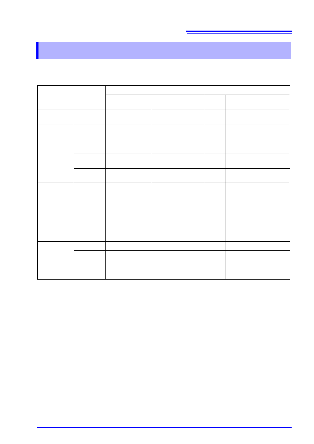
Table of Commands Compatible with the 4288A
4
2. Circuit Compensation :Fully compatible :Partially compatible ×:Incompatible
Setting description
Agilent 4288A HIOKI 3506-10
4288A Command Parameter Compati-
bility Discrepancy
Open Circuit Compensation
ON/ OFF
:CORR:OPEN ON/ OFF/ 1/ 0
Short Circuit Compensation
ON/ OFF
:CORR:SHOR ON/ OFF/ 1/ 0
Load Circuit Compensation
ON/ OFF
:CORR:LOAD ON/ OFF/ 1/ 0
Offset Circuit Compensation
ON/ OFF
:CORR:OFFS ON/ OFF/ 1/ 0
Open Circuit Compensation
Data Parameter Format
:CORR:CKIT:STAN1:
FORM
GB/ CPG
Short Circuit Compensation
Data Parameter Format
:CORR:CKIT:STAN2:
FORM
RX/ LSRS
Standard
Definition for
Load Compen-
sation
Definition
Value
:CORR:CKIT:STAN3 Reference value (1st),
Reference value (2nd)
Reference value (1st):
-999.999 to 999.999
Reference value (2nd):
-99.9999E9 to 99.9999E9
The number of valid set-
ting value digits may de-
crease in accordance with
the number of valid mea-
surement range digits.
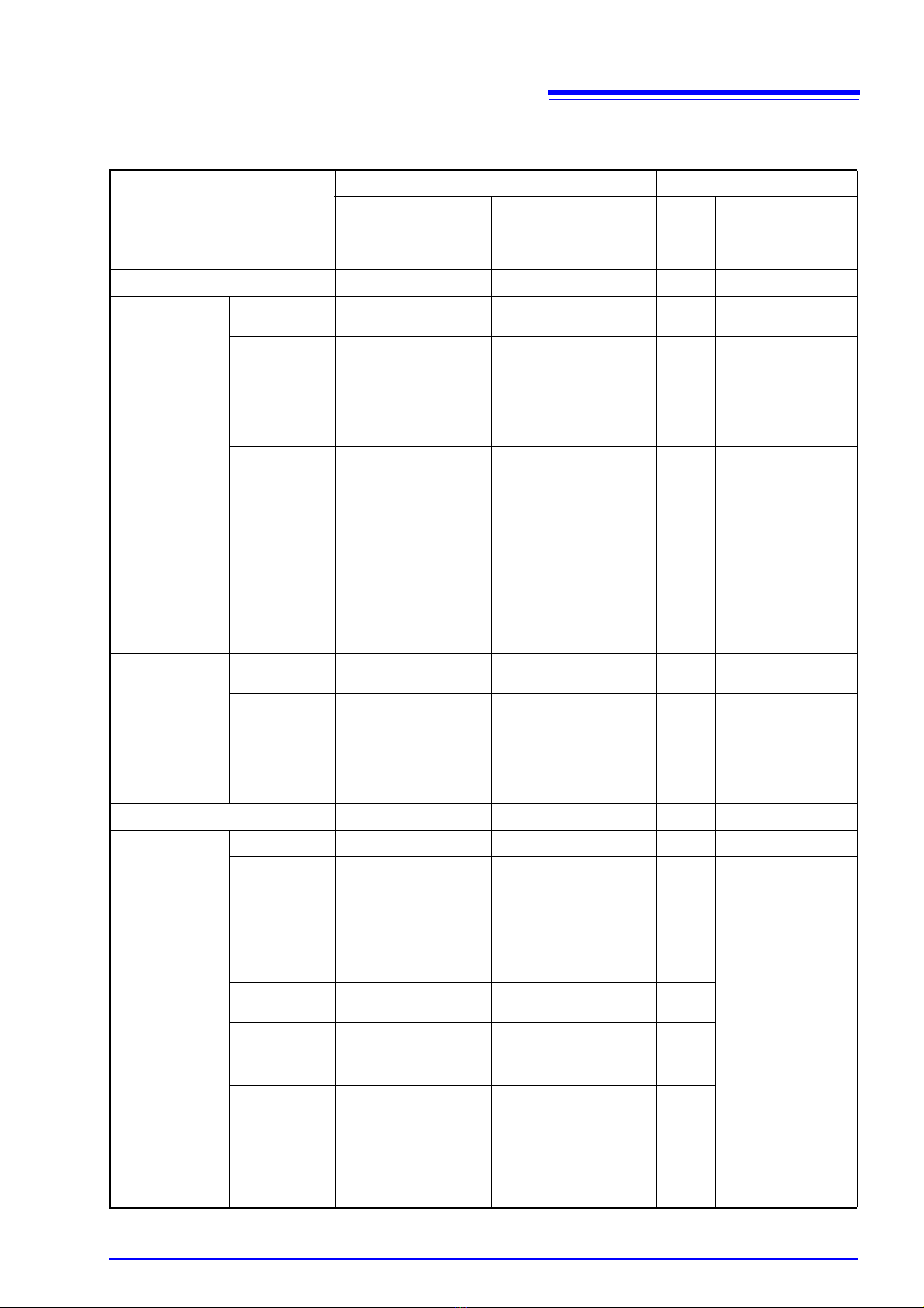
Parameter
Format
:CORR:CKIT:STAN3:
FORM
CPD/ CPQ/ CPG/ CPRP/
CSD/ CSQ/ CSRS Only compatible with CPD/
CSD/ CPQ/ CSQ
Compensa-
tion Data
Measure-
ment
:CORR:COLL STANdard1/ STANdard2/
STANdard3
STAN1:Open Circuit Com-
pensation
STAN2:Short Circuit Com-
pensation
STAN3:Load Circuit Com-
pensation
Setting and
reading
:CORR:DATA STANdard1/STANdard2/
STANdard3,
Compensation value (1st),
Compensation value (2nd)
Compensation value (1st):
-999.999 to 999.999
Compensation value (2nd):
-99.9999E9 to 99.9999E9
The number of valid set-
ting value digits may de-
crease in accordance with
the number of valid mea-
surement range digits.
Offset Compensation Data
Setting
:CORR:OFFS:DATA Compensation value (1st),
Compensation value (2nd)
Compensation value (1st):
-999.999 to 999.999
Compensation value (2nd):
-99.9999E9 to 99.9999E9
The number of valid set-
ting value digits may de-
crease in accordance with
the number of valid mea-
surement range digits.
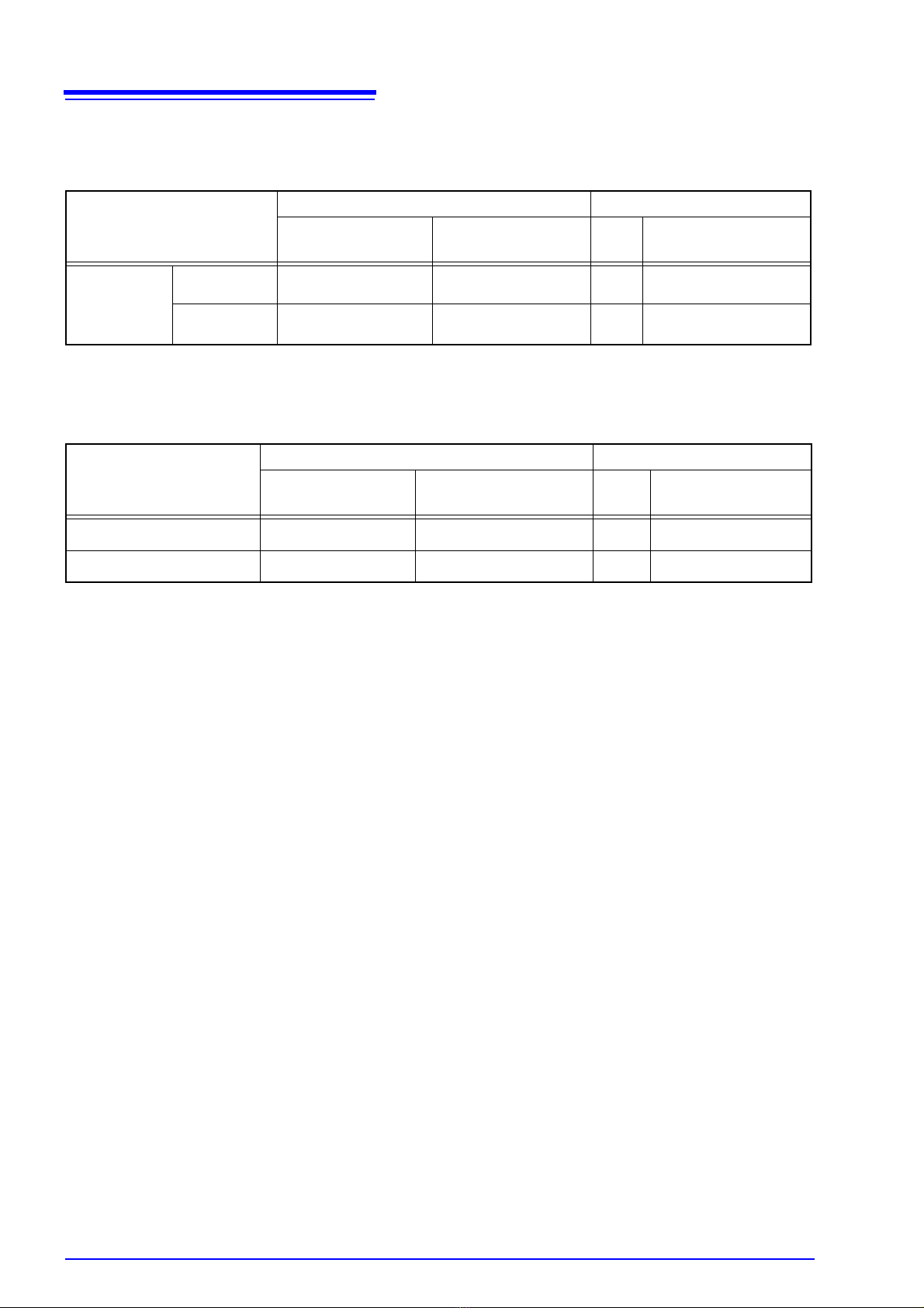
The open circuit compensation and short circuit compensation value is saved at
varying values depending on the measured frequency, signal level, and fre-
quency shift settings.
If these settings are changed and a measurement value has not been taken with
the changed measurement conditions, open circuit compensation and short cir-
cuit compensation will be turned OFF.
However, when the frequency shift or cable length setting is changed, open cir-
cuit compensation and short circuit compensation are set to OFF for all mea-
surement conditions.