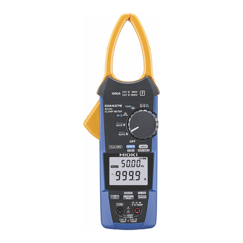
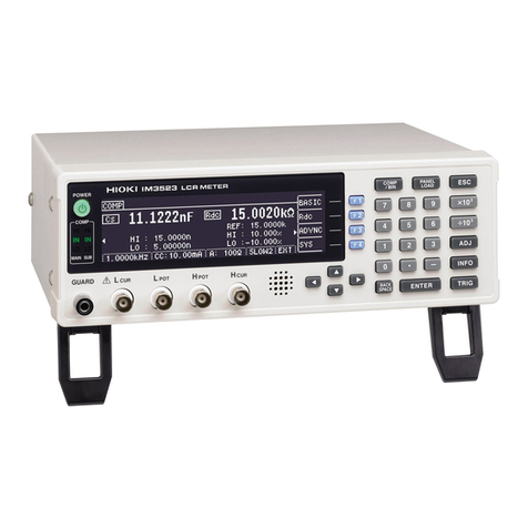
Hioki HiTESTER 3415-02 User manual

INSTRUCTION MANUAL
For...は専用機種。複数の場合は「/」で区切る。
不要の場合はとる。
形名を入力。 複数の場合は「/」で区切る。
3415-02, 3416-02, 3418-01
品名を入力。
TEMPERATURE
HiTESTER


Contents
Introduction i
Safety Notes ii
Inspection iv
Notes on Use v
Chapter 1 Summary 1
1.1 Product Summary 1
1.2 Names and Functions of Parts 3
Chapter 2 Making Measurements 7
2.1 Turning the Power On 7
2.2 Measuring Temperature 7
2.3 Continuous Measurement 12
2.4 How to Specify the Thermal
Emissivity(ε) 12
2.5 Setting the Upper and Lower Alarm
Temperatures 13
2.6 Displaying the Maximum and Minimum
Temperatures 13
2.7 Switching Between Celsius
and Fahrenheit 14
2.8 Switching On the Laser Marker Beem
(3415-02) 14
2.9 Turning the Power Off 14
2.10 Changing the Batteries 15
Chapter 3 Specification 17
3.1 General Specification 3415-02 17
3.2 General Specification 3416-02 19
3.3 General Specification 3418-01 21

Chapter 4 Maintenance and Service 23
4.1 Troubleshooting 25
4.2 Questions and Answers about
Measurement 26

i
―――――――――――――――――――――――――――
Introduction
――――――――――――――――――――――――
Introduction
Thank you for purchasing the HIOKI "3415-
02/3416-02/3418-01 TEMPERATURE
HiTESTER." To obtain maximum
performance from the product, please read
this manual first, and keep it handy for
future reference.

ii
―――――――――――――――――――――――――――
Safety Notes
――――――――――――――――――――――――
WARNING
Mishandling this product during use could result
in injury or death, as well as damage to the
product. Be certain that you understand the
instructions and precautions in the manual before
use. We disclaim any responsibility for accidents
or injuries not resulting directly from product
defects.
In the manual, the symbol indicates
particularly important information that the
user should read before using the
product.
Indicates warnings relating to the laser.
Safety Notes
This manual contains information and
warnings essential for safe operation of the
product and for maintaining it in safe
operating condition. Before using it, be sure
to carefully read the following safety
precautions.
Safety symbols

iii
―――――――――――――――――――――――――――
Safety Notes
――――――――――――――――――――――――
DANGER
Indicates that incorrect operation
presents extreme danger of accident
resulting in death or serious injury to
the user.
WARNING
Indicates that incorrect operation
presents significant danger of accident
resulting in death or serious injury to
the user.
CAUTION
Indicates that incorrect operation
presents possibility of injury to the user
or damage to the equipment.
NOTE
Denotes items of advice related to
performance of the equipment or to its
correct operation.
The following symbols are used in this
Instruction Manual to indicate the relative
importance of cautions and warnings.
・Accuracy
rdg. (displayed or indicated value)
This signifies the value actually being
measured, i.e., the value that is currently
indicated or displayed by the measuring
instrument.

iv
―――――――――――――――――――――――――――
Inspection
――――――――――――――――――――――――
Inspection
・Check before use
Before using the product, inspect it and check
the operation to make sure that the product
was not damaged due to poor storage or
transport conditions. If damage is found,
contact your dealer or HIOKI representative.
When you receive this product, before use,
please check that no abnormality or damage
has occurred during delivery. In particular,
be sure to check the accessories, the liquid
crystaldisplay,thecontrolkeys,andthelens.
In the unlikely event of damage, or if the
product does not function according to
specification, you should immediately contact
the dealer from whom you bought the
product, or the nearest HIOKI service facility.

v
―――――――――――――――――――――――――――
Notes on Use
――――――――――――――――――――――――
DANGER
・Operation of this product according to any
procedure not specified in this manual may
cause explosion due to dangerous laser
radiation.
・The 3415-02 (2-beam laser marker type product)
uses as a light source a semiconducting laser
which emits visible light, and which conforms to
JIS standard class 2 (JIS C6802). (Wavelength
670nm, maximum power output 1 mW)
Since there is considerable danger of this laser
light causing damage to the eyes, be very
careful not to direct this laser light into your
eyes or those of another person.
・Do not look directly into the laser light from the
optical system.
・When measuring the temperature of an object
which has a mirror finish, be careful not to allow
the laser light beam to be reflected off the
surface into your eyes or those of another
person.
・Do not allow the laser light beam to impinge
upon any gas which can explode.
Notes on Use
In order to ensure safe operation and to
obtain maximum performance from the
product, observe the cautions listed below.
vi
―――――――――――――――――――――――――――
Notes on Use
――――――――――――――――――――――――
WARNING
・To avoid electric shock, do not allow the product
to get wet, and do not use it when your hands
are wet.
・If the protective functions of the product are
damaged, either remove it from service or mark
it clearly so that others do not use it
inadvertently.
CAUTION
・Do not use the product near a device that
generates a strong electromagnetic field or
electrostatic charge, as these may cause erroneous
measurements.
・The product should always be operated indoors in a
range from 0℃to 40℃(3415-02), 0℃to 50℃(3416-
02, 3418-01) and 35% to 80% rh or less.
・Do not store or use the product where it could be
exposed to direct sunlight, high temperature or
humidity, or condensation. Under such conditions,
the product may be damaged and insulation may
deteriorate so that it no longer meets specifications.

vii
―――――――――――――――――――――――――――
Notes on Use
――――――――――――――――――――――――
CAUTION
・This product is not designed to be entirely water- or
dust-proof. To avoid damage, do not use it in a wet
or dusty environment.
・Do not use the product where it may be exposed to
corrosive or combustible gases. The product may
be damaged or cause an explosion.
・To avoid damage to the product, protect it from
vibration or shock during transport and handling,
and be especially careful to avoid dropping.
・Do not point the lens at the sun or at any other
source of strong light. If you do, the sensor may be
damaged.
・Do not contact the lens against the object whose
temperature is to be measured, or get it dirty, allow
it to be scratched, or allow any foreign material to
adhere to it. Doing so may cause errors.
NOTE ・Before use, verify that no damage has
occurred due to careless storage or transport,
and check the appearance and operation of
the product.
・When the mark on the display is flashing,
the batteries are low. Fit new batteries.

viii
―――――――――――――――――――――――――――
Notes on Use
――――――――――――――――――――――――
Laser specification
and caution label
Front
Laser caution label
Rear
Warning Labels
Location of labels used in the HIOKI "3415-02
TEMPERATURE HiTESTER" are as follows.

1
―――――――――――――――――――――――――――
Chapter 1 Summary
――――――――――――――――――――――――
Chapter 1
Summary
1.1 Product Summary
1. Theory of Measurement
Every object emits infrared energy in
accordance with its temperature. By
measuring the amount of this radiant energy,
it is possible to determine the temperature of
the emitting object.
2. About infrared
Infrared radiation is a form of light
(electromagnetic radiation), and has the
property that it passes easily through air,
while it is easily absorbed by solid matter.
With an emission thermometer which
operates by detecting infrared radiation,
accurate measurement is possible,
irrespective of the air temperature or the
measurement distance.
3. Emission Thermometer Structure
Infrared radiation which has been emitted
from the object is focused upon an infrared
radiation sensor, via an optical system which
includes a lens which is transparent to

2
―――――――――――――――――――――――――――
Chapter 1 Summary
――――――――――――――――――――――――
infrared radiation, an 8μm cuton filter, etc..
The output signal from the infrared radiation
sensorisinputtoanelectroniccircuitalong
with the output signal from a standard
temperature sensor.
The electronic circuit calculates the object
temperature while applying standard
temperature compensation, thermal
emissivity compensation, etc., and displays
the result.

3
―――――――――――――――――――――――――――
Chapter 1 Summary
――――――――――――――――――――――――
3415-02 2-beam laser
marker type
3418-01 Standard type
3416-02 LED spot
marker type
①Lens
②Laser mark beam
emission openings(3415-02) ③LED mark beam
emission opening
⑦LCD display
④MODE key
⑥MEAS key
⑤Numeric input keys
1.2 Names and Functions of Parts

4
―――――――――――――――――――――――――――
Chapter 1 Summary
――――――――――――――――――――――――
①Lens
Infrared rays from the object whose
temperature is to be measured are received
here.
②Laser marker beam emission openings(3415-02)
The laser marker beams are emitted from
here.
③LED mark beam emission opening(3416-02)
The LED mark beam is emitted from here.
④MODE key
Pressing this key switches the mode around
the cycle ε→ALM↑→↓ALM→MAX→MIN→
HOLD.
・HOLD: After measurement is completed,
the HOLD indication appears, is
illuminated, and the measured value is
held.
・ε: The inherent thermal emissivity of the
object is set using the ▼and ▲keys.
・ALM↑: The upper limit alarm temperature
is set using the ▼and ▲keys.
・↓ALM: The lower limit alarm temperature
is set using the ▼and ▲keys.
・MAX: The maximum temperature during
measurement is displayed.
・MIN: The minimum temperature during
measurement is displayed.

5
―――――――――――――――――――――――――――
Chapter 1 Summary
――――――――――――――――――――――――
⑤Numeric input keys
・▼ key: The numerical value is reduced.
・▲ key: The numerical value is increased.
If either of these numerical value keys is held
down, the numerical value changes rapidly in
the appropriate direction.
⑥MEAS key
When pressed, the power is turned on and
measurement starts. When released,
measurement is terminated.
⑦LCD display
・:Indicates whether the laser marker beam
is on or not. During measurement with the
laser marker beam on, this indication
flashes (3415-02).
・:Shows the amount of battery
capacity remaining. If the battery voltage
drops below the minimum level to
guarantee accuracy, the mark (only)
flashes.
・℃:Turned on when the display is showing
temperature in products of degrees Celsius.
・°
F: Turned on when the display is showing
temperature in products of degrees
Fahrenheit.
・HOLD: Appears when the last measured
temperature value is being held.
・ε: Appears when the thermal emissivity is
being set.

6
―――――――――――――――――――――――――――
Chapter 1 Summary
――――――――――――――――――――――――
・ALM↑: Appears when the upper limit
alarm temperature is being set.
・↓ALM: Appears when the lower limit
alarm temperature is being set.
・MAX: Appears when the maximum
temperature during measurement is being
displayed.
・MIN: Appears when the minimum
temperature during measurement is being
displayed.
・SET: Blinking when a numerical value can
be set.(during setting of ε,ALM↑,and↓
ALM)

7
―――――――――――――――――――――――――――
Chapter 2 Making Measurements
――――――――――――――――――――――――
NOTE
Chapter 2
Making Measurements
2.1 Turning the Power On
2.2 Measuring Temperature
When the power is off, pressing the MEAS
key turns on the power.
ThevaluesandsettingsontheLCDdisplay
return to the state before the power was last
turned off.
・If, from the power off condition, the MEAS
key is held down for more than one second,
measurement starts.
1. Press the MODE key, repeatedly if necessary,
until the (ε) mark lights up.
Refer to the following table and, using the ▼
and ▲keys, set the thermal emissivity for
the object whose temperature is to be
measured.

8
―――――――――――――――――――――――――――
Chapter 2 Making Measurements
――――――――――――――――――――――――
Substance Thermal
emissivity
Substance Thermal
emissivity
Asphalt 0.90 to 0.98 Cloth (black) 0.98
Concrete 0.94 Human skin 0.98
Cement 0.96 Leather 0.75 to 0.80
Sand 0.90 Charcoal
(powder)
0.96
Earth 0.92 to 0.96 Lacquer 0.80 to 0.95
Water 0.92 to 0.96 Lacquer
(matt)
0.97
Ice 0.96 to 0.98 Rubber
(black)
0.94
Snow 0.83 Plastic 0.85 to 0.95
Glass 0.90 to 0.95 Timber 0.90
Ceramic 0.90 to 0.94 Paper 0.70 to 0.94
Marble 0.94 Chromium
oxides
0.81
Plaster 0.80 to 0.90 Copper
oxides
0.78
Mortar 0.89 to 0.91 Iron oxides 0.78 to 0.82
Brick (red) 0.93 to 0.96 Textiles 0.90
NOTE ・Variations in the surface condition and color
of the object whose temperature is to be
measured may cause the thermal emissivity
εto be somewhat different from the values
in the above table. If an accurate
This manual suits for next models
2
Table of contents
Other Hioki Measuring Instrument manuals

Hioki
Hioki 3447-01 User manual

Hioki
Hioki LUX HiTESTER 3423 User manual

Hioki
Hioki PW3198 User manual

Hioki
Hioki PW9100-03 User manual

Hioki
Hioki 3284 HiTester User manual

Hioki
Hioki PQ3198-92 User manual

Hioki
Hioki BT4560 User manual

Hioki
Hioki 9014 User manual

Hioki
Hioki CT6845-05 User manual

Hioki
Hioki DM7275-01 User manual
Popular Measuring Instrument manuals by other brands

CyberOptics
CyberOptics Auto Teaching System ATS quick start guide

HunterLab
HunterLab ColorFlex EZ Tomato quick start guide

Xylem
Xylem wtw Cl 800 DIN operating manual

Burkert
Burkert S030 operating instructions

Campbell
Campbell SkyVUE 8 product manual

Hanna Instruments
Hanna Instruments HI 93720 instruction manual