Hioki 9695-02 User manual

Introduction
Thank you for purchasing the HIOKI 9695-02/03 CLAMP ON SEN-SOR. Toobtain maximum
performance from the product, please read this manual first, and keep it handy for future
reference.
Overview
The 9695-02/03 are voltage-output, clamp-on sensors used for 50 A (9695-02) and 100 A
(9695-03) rated AC measurement.
The 9695-02/03 sensors are designed to measure alternating currents on a hot conductor
without disconnecting it from the power line. Both sensors are easy to operate and suitable
for electric current and power measurement in various fields.
Initial Inspection
When you receive the product, inspect it carefully to ensure that no damage occurred during
shipping. If damage is evident, or if it fails to operate according to the specifications, contact
your dealer or representative.
Maintenance and Service
•To clean the product, wipe it gently with a soft cloth moistened with water or mild detergent. Never
use solvents such as benzene, alco-hol, acetone, ether, ketones, thinners or gasoline, as they
can deform and discolor the case.
• If the product seems to be malfunctioning, contact your dealer or representative. Pack the
product carefully so that itwill notbe damaged during shipment, and include a detailed written
description of the problem. Hioki cannot be responsible for damage that occurs during shipment.
9695-02, 9695-03
CLAMP ON SENSOR
Instruction Manual
July 2015 Revised edition 8 Printed in Japan
9695B980-08 15-07H
Warranty
Warranty malfunctions occurring under conditions of normal use in conformity with the Instruction
Manual and Product Precautionary Markings will be repaired free of charge. This warranty is valid for
a period of one (1) year from the date of purchase. Please contact the distributor from which you
purchased the product for further information on warranty provisions.
www.GlobalTestSupply.com
Find Quality Products Online at: sales@GlobalTestSupply.com

(Accuracy guaranteed for one year at 23°C±5°C(73°F±9°F), 80%RH or less.
Endurance number of the jaw opening and closing part: 10000 times)
f.s. : maximum display value or scale length
rdg.: reading value (The value currently being measured and indicated on the
measuring product)
Follow these precautions to ensure safe operation and to obtain the
full benefits of the various functions.
Measurement categories
This productconforms tothe safety requirements for CAT III measurement
products.
Toensure safe operation of measurement products, IEC 61010 establishes
safety standards for various electrical environments, categorized as CAT II
toCAT IV,and called measurement categories.
CAT II: Primary electrical circuits
in equipment connected to an AC
electrical outlet by a power cord
(portable tools, household appli-
ances, etc.)
CAT IIcoversdirectly measuring
electrical outlet receptacles. CAT
III: Primary electrical cir-cuits
of heavy equipment (fixed
installations) connected directly
to the distribution panel, and
feeders from the distribution panel to outlets.
CAT IV: The circuit from the service drop to the service entrance, and to the
power meter and primary overcurrent protection device (distribution panel).
Using a measurement product in an environment designated with a higher-
numbered category than that for which the product is rated could result in a
severe accident, and must be carefully avoided.
Use of a measurement instrument that is not CAT-rated in CAT II toCATIV
measurement applications could result in a severe accident, and must be care-
fully avoided.
Specifications
Rated primary current 9695-02: 50 A AC, 9695-03: 100 A AC
Output voltage 9695-02: 10 mV AC/A, 9695-03: 1 mV AC/A
Amplitude accuracy
±
0.3% rdg.±0.02%f.s. (f.s.:50 A (
9695-02
)/
100 A (9695-03)
,
45Hz to 66Hz, at jaw center)
Phase accuracy 9695-02: Within
±
2° (45 Hz to 5 kHz)
9695-03: Within
±
1° (45 Hz to 5 kHz)
Amplitude frequency
characteristics Within ±1% at 40 Hz to 5 kHz (deviation from accuracy)
Effect of conductor
position Within ±0.5% (deviation from center)
Effect of external
electromagnetic field 0.1 A equivalent or lower
(in an AC electromagnetic field of 400 A/m)
Maximum permissible
input 60 A continuous (
9695-02)/
130 A continuous (
9695-03
)
(at 45 to 66 Hz, ambient temperature 50
°
C
)
Temperature coefficient 0.02%rdg./
°
C
Dielectric strength
3536
V ACrms for 15 sec (between electric circuit and jaw)
Maximum rated voltage to
earth 300 V ACrms or lower (Insulated conductor)
Operating Temperature
&Humidity 0 to 50
°C (32 to 122°F)
, 80%RH or lower
(non-condensating)
Storage Temperature
&Humidity -10 to 60
°C(14 to 140°F)
, 80%RH or lower
(non-condensating)
Operating Environment Indoors, up to 2000 m (6562-ft.) ASL
Standards applying Safety
EN61010
Measurement Category III, Pollution Degree 2
(Anticipated Transient Overvoltage: 4000 V)
EMC EN61326
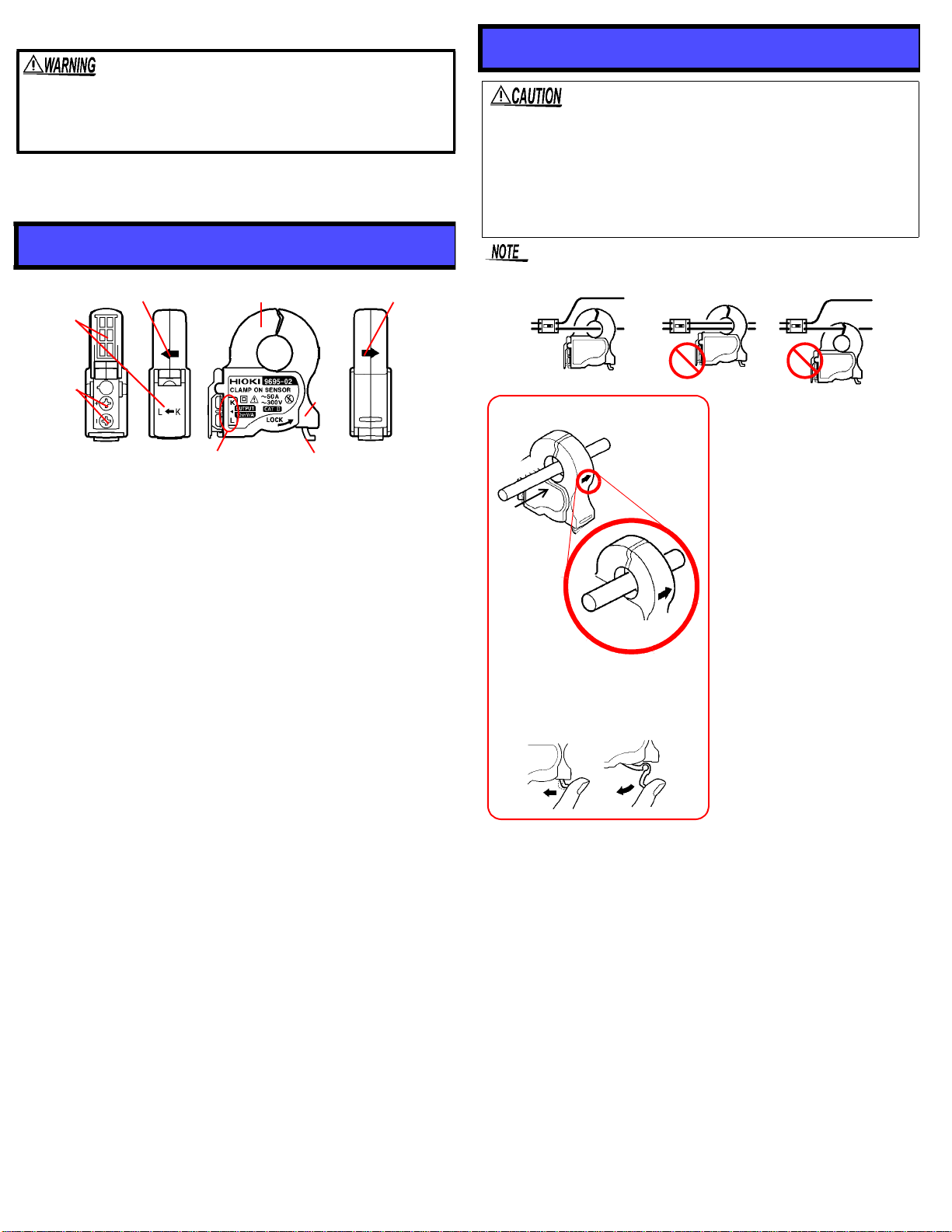
Measurable conductor
diameter 15 mm (0.59”) or less
Output terminals M3 terminal (Maximum outside diameter: 6.5 mm/0.26”, inside
diameter: 3.2 mm/0.13”)
Cable length 3 m or less
Dimensions Approx. 50.5W x 58.0H x 18.7D mm (1.99”W x 2.28”H x
0.74”D) (excluding protrusions)
Mass Approx. 50 g (1.8 oz.)
Accessory Instruction Manual
Option 9219 CONNECTION CABLE, 9238 CLAMP SENSOR CABLE
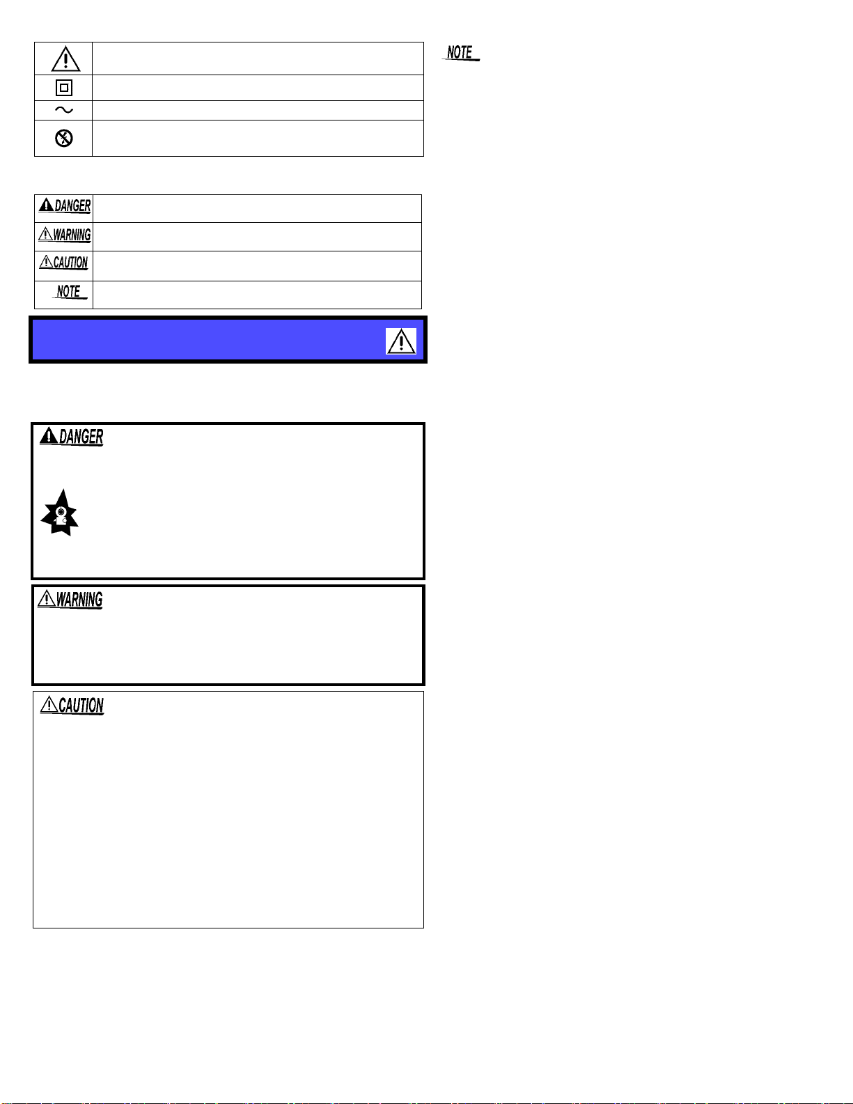
Safety
This product is designed to conform to IEC 61010 Safety Stan-
dards, and has been thoroughly tested for safety prior to ship-
ment. However, mishandling during use could result in injury or
death, as well as damage to the product. Be certain that you
understand the instructions and precautions in the manual
before use. We disclaim any responsibility for accidents or inju-
ries not resulting directly from product defects.
www.GlobalTestSupply.com
Find Quality Products Online at: sales@GlobalTestSupply.com

Safety Symbol
The following symbols in this manual indicate the relative importance
of cautions and warnings.
This manual contains information and warnings essential for safe
operation of the product and for maintaining it in safe operating condi-
tion. Before using the product, be sure to carefully read the following
safety notes.
• Accurate measurement may be impossible in the presence of strong
magnetic fields, such as near transformers and high-current conduc-
tors, or in the presence of strong electromagnetic fields such as near
radio transmitters.
•When connecting the cables to the output terminal, twist the cables
together as close to the terminal as possible to avoid the influence of
an external magnetic field
•Use the 9219 CONNECTION CABLE to connect this product to the
HIOKI clamp wattmeter. (The connector of the 9219 is a
solderless terminal to BNC.)
Indicates cautions and hazards. When the symbol is printed on the
instrument refer to a corresponding topic in the Instruction Manual.
Indicates a double-insulated device.
Indicates AC (Alternating Current).
Wear appropriate protective insulation (insulating rubber gloves
and boots, helmet and etc.) when connecting and disconnecting
from live electric circuits.
Indicates that incorrect operation presents an extreme hazard that
could result in serious injury or death to the user.
Indicates that incorrect operation presents a significant hazard
that could result in serious injury or death to the user.
Indicates that incorrect operation presents a possibility of injury to
the user or damage to the product.
Advisory items related to performance or correct operation of the
product.
Usage Notes
• To avoid short circuits and potentially life-threatening
hazards, never attach the product to a circuit that oper-
ates at more than the 300 V, or over bare conductors.
• This product should only be connected to the sec-
ondary side of a breaker, so the breaker can prevent
an accident if a short circuit occurs. Connections
should never be made to the primary side of a
breaker, because unrestricted current flow could
cause a serious accident if a short circuit occurs.
• To avoid electric shock, do not allow the product to get wet,
and do not use it when your hands are wet.
• To avoid electric shock when measuring live lines, wear
appropriate protective gear, such as insulated rubber gloves,
boots and a safety helmet.
• Note that the product may be damaged if the applied current ex-
ceeds the measurement range.
• Do not store or use the product where it could be exposed to direct
sunlight, high temperature or humidity, or condensation. Under
such conditions, the product may be damaged and insulation may
deteriorate so that it no longer meets specifications.
• Be careful to avoid dropping the clamps or otherwise subjecting
them to mechanical shock, which coulddamage the mating surfac-
es of the core and adversely affect measurement.
• Keep the jaw free from foreign objects, which could interfere with
clamping action.
• Keep the jaw closed when not in use, to avoid accumulating dust
or dirt on the mating jaw, which could interfere with clamp perfor-
mance.
• Do not fix the output terminal screws too tightly. The torque about
0.5N•m is recommended.
www.GlobalTestSupply.com
Find Quality Products Online at: sales@GlobalTestSupply.com

Preliminary Checks
Before using the product the first time, verify that it operates normally
to ensure that the no damage occurred during storage or shipping. If
you find any damage, contact your dealer or representative.
Attach the clamp around only one conductor. Single-phase (2-wire) or
three-phase (3-wire) cables clamped together will not produce any reading.
Before using the product, make sure that no bare
conductors are improperly exposed. Using the product in
such conditions could cause an electric shock, so contact
your dealer or representative for repair.
Parts Names
Measurement Procedures
• Do not disconnect the output cable when the tester connected to
the clamp-on sensor is on or with the sensor clamped on a conduc-
tor to measure. Thisprevents the 9695-02/03 mainunit and sensor
from malfunctioning.
• M3x5 screws and a spring washer assembly should be used for the
9695-02/03 terminals. When using another type of screw (especial-
ly longer ones), be careful with the tightening torque. Tightening a
screw too much may damage the 9695-02/03.
Output
Current direction indicator Current direction indicator
Jaw
Lever
Lock knob
terminals
Cable polarity display
Output
terminal
cover
OK
1. Confirm that the tester con-
nected to the clamp-on sen-
sor is powered off.
2. Open the terminal cover and
connect the cable to the ter-
minal of the 9695-02/03.
Make sure that the polarities
match.
3. Connect the cable to the
input terminal of the tester.
4. Turn on the tester.
5. If the lever is locked, unlock
it.
6. Open the jaw. Orient the cur-
rent direction indicator to the
load side and clamp one con-
ductor at the center of the
jaw.
7. Close the jaw and lock it. Be
sure to lock the clamp core
since it has no spring.
LOAD
SOURCE
Position the clamp with the current
direction indicator pointing toward the
load side. (If installed in the opposite
direction,the phase deviates 180
degrees.)
Current direction
indicator
Clamp the conductor.
Electric
conductor
Unlock the lever
12
When output cover
is opened
www.GlobalTestSupply.com
Find Quality Products Online at: sales@GlobalTestSupply.com
This manual suits for next models
1
Other Hioki Measuring Instrument manuals

Hioki
Hioki CM4002 User manual

Hioki
Hioki PQ3100 User manual

Hioki
Hioki 8715-01 User manual

Hioki
Hioki 3227 User manual

Hioki
Hioki FT3432 User manual

Hioki
Hioki Hioki User manual

Hioki
Hioki HiTester 3443-01 User manual

Hioki
Hioki PW3198 User manual

Hioki
Hioki IM3523 Use and care manual

Hioki
Hioki MEMORY HiCORDER MR8870-20 User manual
Popular Measuring Instrument manuals by other brands

SUTO
SUTO S418-V Instruction and operation manual

Salutron
Salutron D2X user manual

Fluid Components Intl
Fluid Components Intl ST51A Installation, Operation & Maintenance Instruction Manual

Balluff
Balluff BIS M-4008-048-0 ST4 PROFINET Series operating manual

SensorLink
SensorLink True RMS Ampstik 8-020 Operator's manual

Domintell
Domintell Dcare user manual