Hioki 3174 User manual

INSTRUCTION MANUAL
3174
3174-01
AC AUTOMATIC
WITHSTANDING HiTESTER
INSULATION/


Contents
i
Contens
Introduction.................................................................................1
Confirming Package Contents....................................................1
Safety Information......................................................................2
Operating Precautions................................................................4
Chapter 1
Overview ___________________________________ 7
1.1 Product Overview .........................................................7
1.2 Features .......................................................................7
1.3 Names and Functions of Parts .....................................9
1.3.1 3174 (3174-01) ................................................................9
1.3.2 Display ..........................................................................12
1.3.3 Model 9615 H.V.Test Lead ...........................................13
1.4 External Dimensions ..................................................14
1.5 Testing Process .........................................................15
Chapter 2
Testing Arrangements ________________________ 17
2.1 Arrangements Work Flow ...........................................17
2.2 Connecting the Protective Conductor Terminal .........18
2.3 Connecting the Power Cord .......................................19
2.4 Connecting the Test Lead ..........................................20
2.4.1 When using the Contact Check Function ......................21
2.4.2 When not using the Contact Check Function ................23
2.5 Turning the Power On and Off ...................................24
2.6 Pre-test Check ...........................................................26
Chapter 3
Withstand-Voltage Test _______________________ 29
3.1 Setting the Test-Conditions ........................................31
3.1.1 Setting the Test-Voltage Value .....................................32
3.1.2 Setting the Upper (Lower) Limit Value ..........................33
3.1.3 Setting the Test Time Timer ..........................................34
1
2
3
Appendix
Index

Contents
ii
3.1.4 Setting the Ramp-up (Ramp-down) Time Timer ...........35
3.1.5 Setting the Test-Frequency ..........................................36
3.1.6 Setting the Initial voltage for ramp-up ...........................37
3.1.7 Setting the Confirmation Voltage
used for upper and lower-limits for Contact Check .......38
3.2 Starting a Test ........................................................... 40
3.3 Terminate the Test .................................................... 42
3.4 Displaying the Test Result ......................................... 44
3.4.1 "PASS" Determination ..................................................45
3.4.2 "FAIL" Determination ....................................................46
Chapter 4
Insulation-Resistance Test_____________________47
4.1 Setting the Test Conditions ....................................... 49
4.1.1 Setting the Test-Voltage Value .....................................50
4.1.2 Setting the Upper (Lower) Limit Value ..........................51
4.1.3 Setting the Test Time Timer .........................................53
4.1.4 Setting the Delay Time .................................................54
4.1.5 Setting the Confirmation Voltage
used for upper and lower-limits for Contact Check .......55
4.2 Starting a Test ........................................................... 57
4.3 Terminate the Test .................................................... 59
4.4 Displaying the Test Result ......................................... 61
4.4.1 "PASS" Determination ..................................................62
4.4.2 "FAIL" Determination ....................................................63
4.4.3 Influence of capacity on the test result (reference data) 65
Chapter 5
Automatic Test ______________________________69
5.1 Setting the Test Conditions ....................................... 70
5.2 Starting a Test ........................................................... 71
5.3 Terminate the Test .................................................... 73
5.4 Displaying the Test Result ......................................... 75
5.4.1 "PASS" Determination ..................................................76
5.4.2 "FAIL" Determination ....................................................78
Chapter 6
Useful Functions_____________________________79
6.1 Functions for carrying out the tests safely ................. 79
6.1.1 Key-lock Function .........................................................79

Contents
iii
6.1.2 Momentary Out .............................................................80
6.1.3 Double Action ................................................................81
6.1.4 START Protection .........................................................82
6.1.5 Output-Voltage Restricting ............................................83
6.2 Display Hold (Hold Function) .....................................84
6.2.1 PASS Hold ....................................................................85
6.2.2 FAIL Hold ......................................................................86
6.2.3 STOP Hold ....................................................................87
6.3 Evaluate even for forced termination of test ...............88
6.4 Continue testing even after FAIL result is shown
(Continuous Test Mode, Only Withstanding-Test) .....89
6.5 Limiting the FAIL Hold Cancellation (FAIL mode) ......90
6.6 Changing the Output Voltage
during the withstanding test .......................................91
6.7 Insulation-Resistance Test Termination Mode ...........92
6.8 Auto-range for insulation-resistance test ....................95
6.9 Status Out ..................................................................96
Chapter 7
Saving / Loading test conditions ________________ 99
7.1 Saving the Test Conditions ........................................99
7.2 Loading the Test Conditions ....................................102
Chapter 8
External Interface___________________________ 103
8.1 Outline of External I/O ..............................................103
8.1.1 Explanations of signal line ...........................................104
8.1.2 Connecting the External I/O connector .......................106
8.2 Example of Signal Connection .................................107
8.3 Inter-lock Function ....................................................111
8.4 TEST-Signal Output .................................................113
8.5 Selecting test mode and
saved test condition 114
8.6 Timing Chart .............................................................115
8.7 Adjusting the Buzzer sound .....................................119
Chapter 9
RS-232C/GP-IB Interface ____________________ 121
4
5
6
7
8
9
10
11
3
Appendix
Index

Contents
iv
9.1 Specifications .......................................................... 122
9.2 Connection and Setting Procedures ........................ 123
9.2.1 Connecting the Connector ..........................................123
9.2.2 Setting the Communication Conditions .......................125
9.3 Communication Methods ......................................... 127
9.3.1 Message Format .........................................................128
9.3.2 Output Queue and Input Buffer ...................................131
9.3.3 Status Byte Register ...................................................132
9.3.4 Event Registers ..........................................................134
9.3.5 Initialization Items .......................................................137
9.3.6 Local Function ............................................................137
9.3.7 Command Reference List ...........................................138
9.4 Message Reference ................................................ 142
9.4.1 Common Command ....................................................143
9.4.2 Device-Specific Commands ........................................148
9.4.3 Transmission and response formats ...........................181
9.4.4 Sample program Flowchart .........................................182
9.5 Interface Command "START" .................................. 186
Chapter 10
Specifications______________________________187
10.1 Basic Specifications ................................................. 187
10.2 General Specifications ............................................. 193
10.3 H.V.Test Lead (Accessory) Specifications .............. 194
Chapter 11
Maintenance and Service_____________________195
11.1 Troubleshooting ....................................................... 195
11.2 Cleaning .................................................................. 196
11.3 Error Indication ........................................................ 197
11.4 System Reset .......................................................... 198
Appendix _________________________________ A 1
Appendix1 Remote Control Box..........................................A 1
Appendix2 List of Optional Functions .................................A 5
Index__________________________________ Index i

Introduction
1
Thank you for purchasing the HIOKI “Model 3174, 3174-01 AC Automatic Insula-
tion/Withstanding HiTester.” To obtain maximum performance from the instru-
ment, please read this manual first, and keep it handy for future reference.
• When you receive the instrument, inspect it carefully to ensure that no dam-
age occurred during shipping. In particular, check the accessories, panel
switches, and connectors. If damage is evident, or if it fails to operate accord-
ing to the specifications, contact your dealer or Hioki representative.
• When transporting the instrument, use the original packing materials in which
it was shipped, and pack in a double carton. Damage occurring during trans-
portation is not covered by warranty.
* The 3174-01 AC Automatic Insulation/Withstanding HiTester can be used with
GP-IB.
Options 9613 Remote Control Box (Single)
9614 Remote Control Box (Dual)
9615 H.V.Test Lead
9616 Warning Lamp
9267 Safety Test Data Management Software
9637 RS-232C Cable (1.8 m, 9-pin to 9-pin)
9638 RS-232C Cable (1.8 m, 9-pin to 25-pin)
9151-02 GP-IB Connector Cable (2 m)
9151-04 GP-IB Connector Cable (4 m)
Introduction
Confirming Package Contents
Model 3174 (-01) AC Automatic Insula-
tion/Withstanding HiTester
..........................................................1
Model 9615 H.V.Test Lead
.......................... (HIGH/ LOW, 1 each)
Power Cord.......................................1 Slip Prevention Plate.........................1
Instruction Manual..........................1

Safety Information
2
Safety Symbols This manual contains information and warnings essential for safe operation of
the instrument and for maintaining it in safe operating condition. Before using it,
be sure to carefully read the following safety precautions.
The following symbols in this manual indicate the relative importance of cautions
and warnings.
Safety Information
This instrument is designed to comply with IEC 61010 Safety Standards,
and has been thoroughly tested for safety prior to shipment. However, mis-
handling during use could result in injury or death, as well as damage to
the instrument. Using this instrument in ways other than those specified in
this manual may damage functions which guarantees the safety of this
instrument. Be certain that you understand the instructions and precau-
tions in the manual before use. We disclaim any responsibility for acci-
dents or injuries not resulting directly from instrument defects.
In the manual, the symbol indicates particularly important informa-
tion that the user should read before using the instrument.
The symbol printed on the instrument indicates that the user
should refer to a corresponding topic in the manual (marked with the
symbol) before using the relevant function.
Indicates that dangerous voltage may be present at this terminal.
Indicates DC (Direct Current).
Indicates AC (Alternating Current).
Indicates a grounding terminal.
Indicates a protective conductor terminal.
Indicates the ON side of the power switch.
Indicates the OFF side of the power switch.
Indicates that incorrect operation presents an extreme haz-
ard that could result in serious injury or death to the user.
Indicates that incorrect operation presents a significant
hazard that could result in serious injury or death to the
user.
Indicates that incorrect operation presents a possibility of
injury to the user or damage to the instrument.
Indicates advisory items related to performance or correct
operation of the instrument.

Safety Information
3
Other symbols
Accuracy We define measurement tolerances in terms of f.s. (full scale), rdg. (reading) and
dgt. (digit) values, with the following meanings:
f.s. (maximum display value or scale length)
The maximum displayable value or scale length. This is usually the name of the
currently selected range.
rdg. (reading or displayed value)
The value currently being measured and indicated on the measuring instrument.
dgt. (resolution)
The smallest displayable unit on a digital measuring instrument, i.e., the input
value that causes the digital display to show a "1" as the least-significant digit.
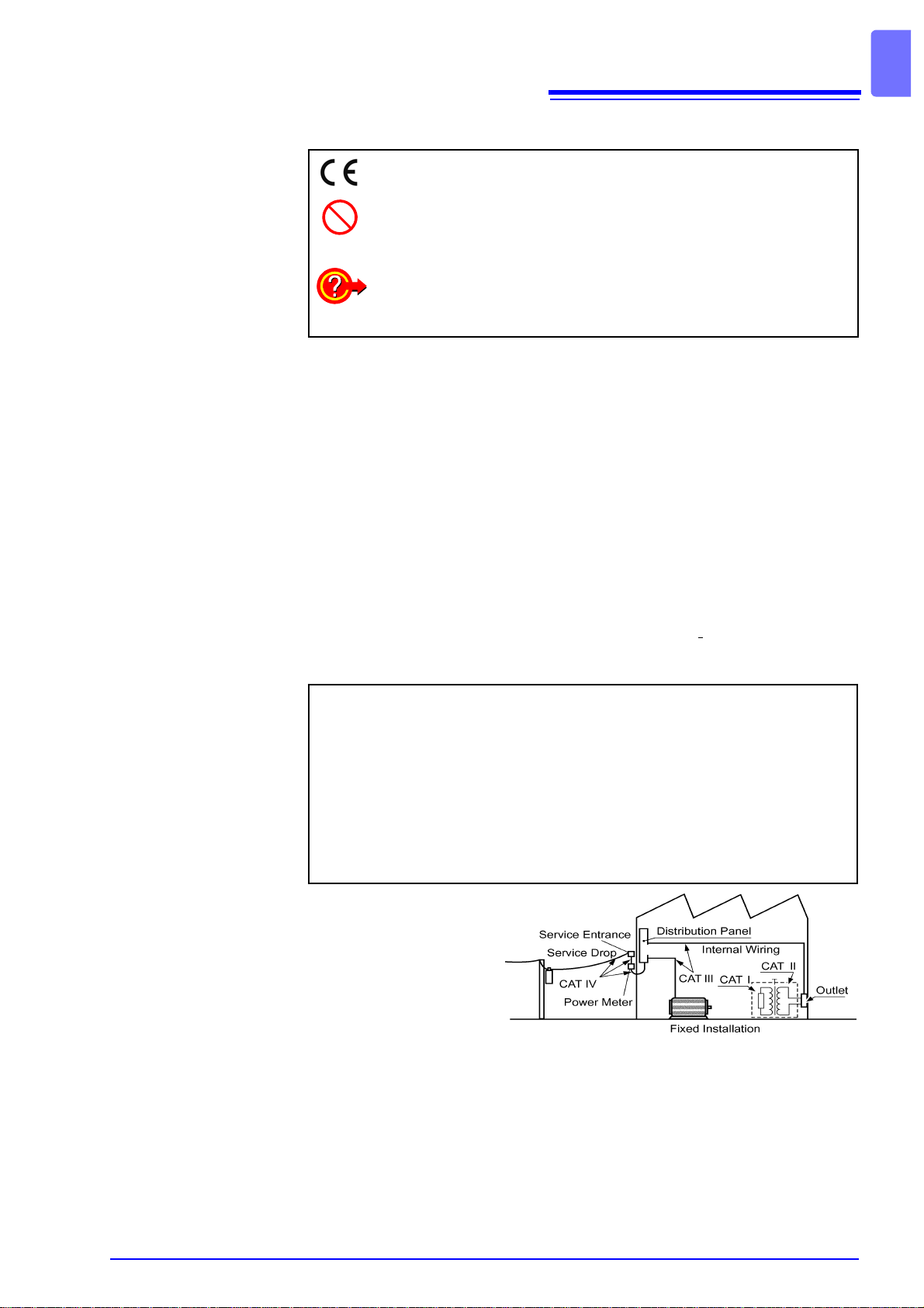
Measurement categories (Overvoltage categories)
This instrument complies with CAT I, CAT II safety requirements.
To ensure safe operation of measurement instrument, IEC 61010 establishes
safety standards for various electrical environments, categorized as CAT I to
CAT IV, and called measurement categories. These are defined as follows.
Higher-numbered catego-
ries correspond to electri-
cal environments with
greater momentary
energy. So a measurement
instrument designed for
CAT III environments can
endure greater momen-
tary energy than a instru-
ment designed for CAT II.
Using a measurement instrument in an environment designated with a higher-
numbered category than that for which the instrument is rated could result in a
severe accident, and must be carefully avoided.
Never use a CAT I measuring instrument in CAT II, III, or IV environments.
The measurement categories comply with the Overvoltage Categories of the
IEC60664 Standards.
This symbol indicates that the product conforms to safety regulations
set out by the EC Directive.
Indicates a prohibited action.
(p. ) Indicates the location of reference information.
Indicates quick references for operation and remedies for trouble-
shooting.
*Indicates that descriptive information is provided below.
CAT I: Secondary electrical circuits connected to an AC electrical outlet
through a transformer or similar instrument.
CAT II: Primary electrical circuits in equipment connected to an AC electrical
outlet by a power cord (portable tools, household appliances, etc.)
CAT III: Primary electrical circuits of heavy equipment (fixed installations)
connected directly to the distribution panel, and feeders from the dis-
tribution panel to outlets.
CAT IV: The circuit from the service drop to the service entrance, and to the
power meter and primary overcurrent protection instrument (distribu-
tion panel).

Operating Precautions
4
Operating temperature and humidity:
0 to 40°C at 80% RH or less (no condensation)
Temperature and humidity range for guaranteed accuracy:
23±5°C, 80%RH or less (no condensation)
after 10 minutes minimum warm-up
Installation • The instrument should be operated only with the bottom side downwards.
• Vents must not be obstructed.
Operating Precautions
Instrument Installation
Avoid the following locations that could cause an accident or damage
to the instrument.
Exposedto directsun-
light
Exposed to high tem-
perature
In the presence of cor-
rosive or explosive
gases
Exposed to liquids
Exposed to high hu-
midity or condensa-
tion
Exposed to strong
electromagnetic fields
Near electromagnetic
radiators
Exposed to high lev-
els of particulate dust Subject to vibration
Ventilation holes Ventilation holes
Spacing of more
than 10 cm Spacing of more
than 10 cm

Operating Precautions
5
Before using the instrument the first time, verify that it operates normally to
ensure that the no damage occurred during storage or shipping. If you find any
damage, contact your dealer or Hioki representative.
Before Use
Before using the instrument, make sure that the insulation on the test
leads is undamaged and that no bare conductors are improperly exposed.
Using the instrument in such conditions could cause an electric shock, so
contact your dealer or Hioki representative for replacements. (Model 9615
H.V.Test Lead)
Handling the Instrument
• To avoid electric shock, do not remove the instrument's case. The inter-
nal components of the instrument carry high voltages and may become
very hot during operation.
• To avoid damage to the instrument, protect it from physical shock when
transporting and handling. Be especially careful to avoid physical shock
from dropping.
Handling the test leads
• For safety reasons, when taking measurements, only use the 9615 H.V. Test
Lead provided with the instrument.
• To avoid breaking the test leads, do not bend or pull them.
Safety Precautions during Testing
To prevent electric shock, when the DANGER lamp is lit or during the test,
never touch the voltage output terminals, test lead, or the tested object.
Tested object

Operating Precautions
6

1.1 Product Overview
7
1
Inaccuracies in measurements have been noted to occur during the withstand-
voltage and insulation-resistance tests because of variations in the test voltage
caused by fluctuations in the voltage supply, breaking of the test leads and
improper connection.
Model 3174, 3174-01 AC Automatic Insulation/Withstanding HiTester is an
affordable insulation/withstanding testing instrument equipped with stable volt-
age supply and contact check functions to prevent a decrease in testing reliabil-
ity caused by these factors.
In addition, to improve the efficiency of the testing process on the production
line, it allows testing settings to be retrieved from both RS-232C (GP-IB) as well
as EXT I/O.
Once test conditions have been pre-set beforehand, withstanding and insulation-
resistance tests which meet industrial standards can be carried out with just the
simple push of a button. Functions such as PASS-FAIL evaluation based on
upper-limit and lower-limit test values, testing time timer, ramp-up/ramp-down
time timer to control voltage fluctuations ensure accurate test results are
obtained.
Once test conditions required for the various industrial standards and device to
be tested have been saved, tests can be carried out smoothly by just switching
to the required test conditions. Up to 8 conditions can be saved for the with-
standing and insulation-resistance tests respectively. In addition, test conditions
for the last test are automatically retrieved when the power is switched on.
Overview Chapter 1
1.1 Product Overview
Front Panel Rear Panel
1.2 Features
Carry out standards-based tests with simple operations
Saving and loading test conditions

1.2 Features
8
Withstanding and insulation-resistance tests can be carried out consecutively
when the respective test conditions have been pre-set. Pressing the W→Ikey
will automatically run the withstanding test followed by the insulation-resistance
test, pressing the I→Wkey will automatically run the insulation-resistance test
followed by the withstanding test.
With the contact check function, the reliability of tests carried out improves with-
out the need to increase testing time (Another set of the 9615 H.V. Test Lead is
necessary)
By showing the real execution value, tests faithful to industrial standards are car-
ried out.
By using PWM switching power supply, the desired voltage supply can be set so
even if the supply voltage fluctuates within ±10% of the preset value, the test
voltage will not be affected. This improves the reliability of the test results.
Under normal conditions, testing immediately stops when the test fails, making it
impossible to determine whether the cause is because of a short circuit or a
value exceeding the threshold value. The Test Continuation Status allows the
test to continue even after a FAIL result is obtained, thus making it possible to
analyze the problem.
This instrument is equipped with EXT I/O as a standard package. This enables
signal transmissions from EXT I/O, start and stop controls of tests and retrievals
of saved test conditions.
This instrument is equipped with RS-232C as a standard package and the 3174-
01 is also equipped with GP-IB as a standard package. By connecting to a com-
puter, they allow for auto testing to be carried out and test results to be read.
Big-sized fluorescent display tubes are used for the display, allowing test condi-
tions and test results to be confirmed easily.
When the optional Remote Control Box is connected to the instrument, test start
or test stop functions can be performed without touching the instrument, thus
making test administrations safer. The 9613 Remote Control Box (Single), 9614
Remote Control Box (Dual) are available.
Automatically carry out consecutive withstanding and insulation-
resistance tests
Contact check function to increase testing reliability
Real execution value shown
Cutting out influence from supply voltage fluctuations
Continuation of testing even after test failure makes analysis of
sample possible (Test Continuation status)
EXT I/O in standard package
RS-232C (Standard Package)/GP-IB Interface (Standard Package
for 3174-01 only)
Easy-to-see big screen
Remote Control Box for safer test administrations (optional)

1.3 Names and Functions of Parts
9
1
Explanations on names and parts of instrument.
1.3 Names and Functions of Parts
1.3.1 3174 (3174-01)
Front Panel
Display
(p. 12) Operation Keys
(p. 10)
POWER Switch
Turns the instrument on and off.
: Power on
: Power off
(The diagram shows a 3174 AC Au-
tomatic Insulation/Withstanding
HiTester.)
Connection terminal for
remote control
Connect the remote con-
trol box (optional)
Pleasecarryoutthetestregularlyon theinstrument
by following the test procedures in "2.6 Pre-test
Check" (p. 26).
See "6.1.3 Double Action" (p. 81)
START Key
Start a test.
(Functions only when the lamp is lit.)
STOP Key
Terminate a test.
HIGH Voltage output terminal
The HIGH terminal is a high-volt-
age terminal for voltage outputs.
LOW Voltage output terminal
The LOW terminal is a low-volt-
age terminal for voltage outputs.
It has the same electric potential
as the unit body.
DANGER lamp
Light blinks to warn of voltage supply.
To prevent electric shock, when the
DANGER lamp is lit, never touch
the voltage output terminals, test
lead, or the tested object.

1.3 Names and Functions of Parts
10
Operation Keys
Moves the flashing cursor to the left.
Moves the flashing cursor to the right.
Raise the selected value with the flashing cursor.
Lower the selected value with the flashing cursor.
Change the ON/OFF for the selected setting with the flashing
cursor. If turned off, the set value is not used in testing.
• The following item can't perform the switching on/off:
Withstand-voltage test:
Test-voltage value, Test-voltage frequency, Upper-limit test
value
Insulation-resistance test:
Test-voltage value, Lower-limit test value
UNLOCK
(LOCAL)
Used to lock the keys.
Only the following keys are available during Key Lock. (p. 79)
UNLOCK key (LOCK + SHIFT key)
START key
STOP key
• In the remote state, this key functions as a LOCAL key.
It cancels the remote state.
Used in combination with other keys.
•SHIFT + key
Displaying the loading screen.(p. 102)
•SHIFT + key
Displaying the saving screen.(p. 99)
•SHIFT + LOCK key
Cancels the key lock.
When GP-IB is used for communication, go to LOCAL state.
•SHIFT + / key
Changing the increment size of setting values.
Performs withstand-voltage tests and settings.
"Chapter 3 Withstand- Voltage Test" (p. 29)
Performs insulation-resistance tests and settings.
"Chapter 4 Insulation- Resistance Test" (p. 47)
Tests for withstand-voltage, then insulation-resistance.
"Chapter 5 Automatic Test" (p. 69)
Tests for insulation-resistance, then withstand-voltage.
"Chapter 5 Automatic Test" (p. 69)

1.3 Names and Functions of Parts
11
1
The diagram shows a 3174-01 (with GP-IB) AC Automatic Insulation/Withstand-
ing HiTester.
Rear Panel
GP-IB connector (3174-01)
Used for remote control with
GP-IB.
EXT I/O connector
For output of 3174 state
and input of start and stop
signals.
RS-232C connector
Used for remote con-
trol with RS-232C.
Power Inlet
Connect the supplied power cord
here
LOW contact check terminal
A low-voltage terminal for contact check.
Protective conductor terminal
Used to earth a protective
ground wire. Be sure to make
grounding connections before
starting a test.
Status Out Relay Terminal
When conditions pre-set in the Status
Out setting are met, the relay connec-
tion gets switched ON.
Buzzer adjustment knob
Used for buzzer sound adjustment.
Two knobs are provided: one for PASS
screening and one for FAIL screening.
LOW voltage output terminal
A low-voltage terminal for voltage
output. Contains the same electrical
potential as this units casing.
HIGH voltage output terminal
A high-voltage terminal for volt-
age output. Connected to the
HIGH terminal on the front panel.
HIGH contact check terminal
A high-voltage terminal for contact check.
Use the Slip Prevention Plate.

1.3 Names and Functions of Parts
12
Test setting conditions and current status of the instrument are shown in the
panel on front of the instrument.
1.3.2 Display
Test type “AC” lights up during withstanding testing.
“DC” lights up during insulation-resistance testing.
Test-voltage value
During testing and READY:
Monitors and indicates the voltage of the output ter-
minal.
During voltage setting:
Indicates the each item set. (output voltage, Con-
tact Check upper (lower)-limit voltage)
Reverse current cannot be detected because monitor
shows voltage and residual voltage.
Upper-limit value icon Lights up when indicating the upper-limit test value.
Lower-limit value icon Lights up when indicating the lower-limit test value.
Upper-limit test value
Lower-limit test value
Indicates the upper-limit test value when the upper-
limit value icon lights up and indicates the lower-limit
test value when the lower-limit value icon lights up.
Also indicates the Contact Check upper-limit voltage
when [Hi] is shown in Test Frequency and Initial
Ramp-up Voltage, and indicates the Contact Check
lower-limit voltage with [Lo].
Test time
Ramp-up time
Ramp-down time
Delay time
Indicates testing time.
Indicates the ramp-up time when [UP] is shown in Test
Frequency and Initial Ramp-up Voltage, and indicates
the ramp-down time together with [dn].
Indicates the delay time together with [dL] during insu-
lation-resistance testing.
Test-frequency
Initial voltage for
ramp-up
Indicates Test Frequency (50 Hz/60 Hz) when [Hz] is
shown. Indicates the Initial Voltage (proportion to Test-
ing Voltage) when Ramp-up Timer is being used
within the range of 0 to 1.0.
Test-voltage value
Upper-limit value icon
Lower-limit value icon
Upper-limit test value
Lower-limit test value
Test time
Ramp-up time
Ramp-down time
Delay time
Test-frequency
Initial voltage for ramp-up
Test type
Indicates the current condition of the instrument
: The instrument is ready for starting a test
.
: The instrument is in the TEST state.
: The tested object passed the test.
: The tested object failed to pass the test.
SAVE: Saving screen
LOAD: Loading screen

1.3 Names and Functions of Parts
13
1
Explanations on names and parts of Test Lead.
1.3.3 Model 9615 H.V.Test Lead
To prevent electric shock, when the DANGER lamp is lit or during the test,
never touch the voltage output terminals, test lead, or the tested object.
There is no insulation/withstand-voltage on the Alligator clip vinyl cover-
ing.
Tested object
9615 H.V.Test Lead
Alligator Clip
Connect to a test point on the test-
ed object.
Alligator Clip
High-voltage output plug
Connect totheHIGHvoltage output
terminal on the instrument.
Low-voltage output plug
Connect to the LOW voltage output
terminal on the instrument.

1.4 External Dimensions
14
Model 3174, 3174-01 AC Automatic Insulation/Withstanding HiTester
1.4 External Dimensions
This manual suits for next models
1
Table of contents
Other Hioki Test Equipment manuals

Hioki
Hioki 3145 User manual

Hioki
Hioki 3665-20 User manual

Hioki
Hioki MEMORY HiCORDER 8855 User manual

Hioki
Hioki 3257-50 User manual

Hioki
Hioki 3802-50 User manual

Hioki
Hioki 3286 User manual

Hioki
Hioki IR4057-50 User manual

Hioki
Hioki IR3455 User manual

Hioki
Hioki BT3554-50 User manual

Hioki
Hioki 3169-20 Instruction manual
Popular Test Equipment manuals by other brands

Fluke
Fluke 5790A Operator's manual

Berkeley Varitronics Systems
Berkeley Varitronics Systems Cicada manual

Colorlight
Colorlight Calibration Pro user manual

Keysight Technologies
Keysight Technologies N5224AU-401 Installation note

Aeroflex
Aeroflex 8800 Series Maintenance manual

Tektronix
Tektronix 454A Operator's handbook