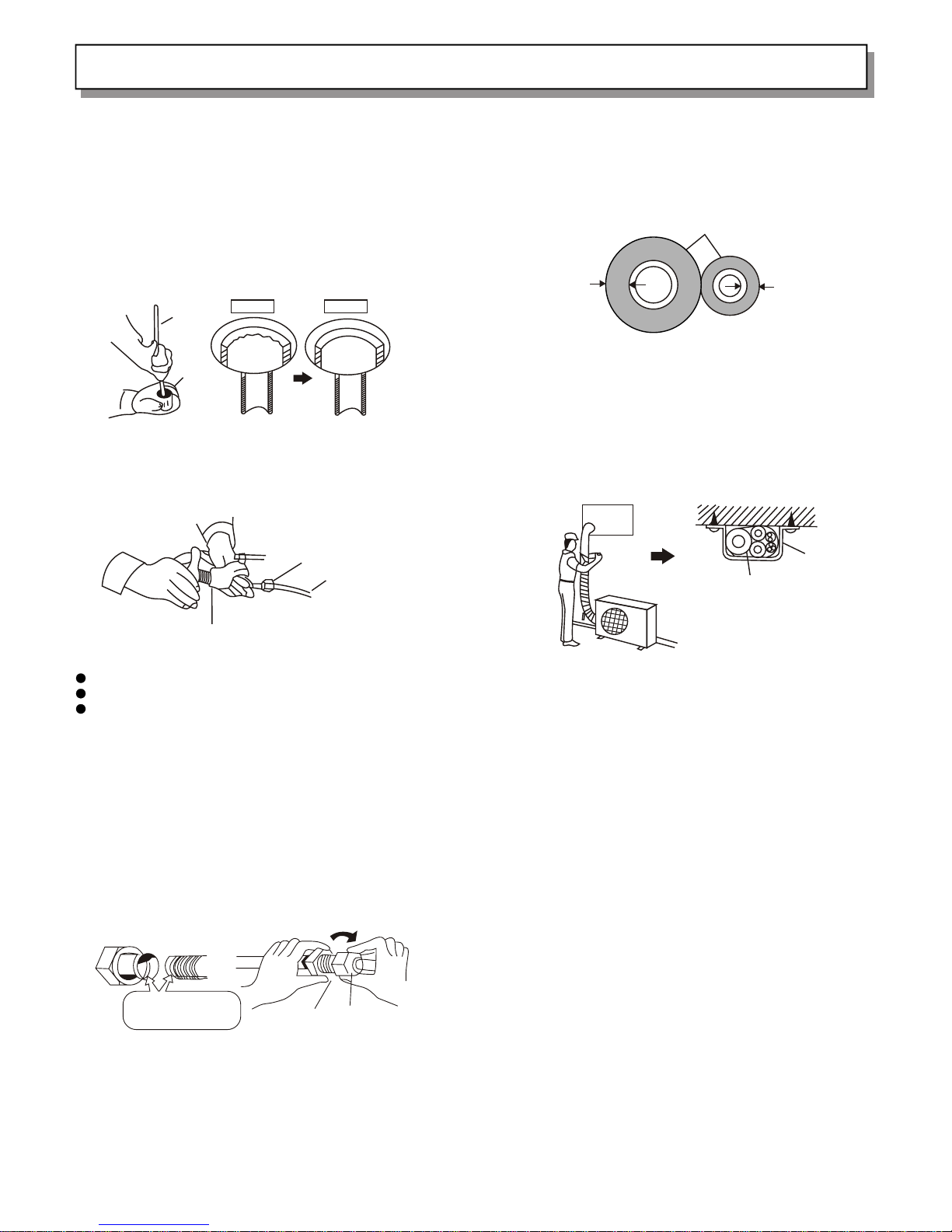
manuals.online logo
Brands
  1. Home
  2. •
  3. Brands
  4. •
  5. Hisense
  6. •
  7. Air Conditioner
  8. •
  9. Hisense KF-1802GWE Parts list manual

Hisense KF-1802GWE Parts list manual

Other Hisense Air Conditioner manuals

Hisense AW0823TW1W Technical specifications

Hisense

Hisense AW0823TW1W Technical specifications

Hisense AMW2-12U4RRA Operating manual

Hisense

Hisense AMW2-12U4RRA Operating manual

Hisense AUD-18UX4SGKL User manual

Hisense

Hisense AUD-18UX4SGKL User manual

Hisense AS-07HR4SYDDEB User manual

Hisense

Hisense AS-07HR4SYDDEB User manual

Hisense AS-36HR4SDKVT User manual

Hisense

Hisense AS-36HR4SDKVT User manual

Hisense AUD-18HX4SUNL1 Operating manual

Hisense

Hisense AUD-18HX4SUNL1 Operating manual

Hisense Hi-FLEXi S Series Instruction Manual

Hisense

Hisense Hi-FLEXi S Series Instruction Manual

Hisense AP1222CW1W Technical manual

Hisense

Hisense AP1222CW1W Technical manual

Hisense AS-09HR4SVCUH User manual

Hisense

Hisense AS-09HR4SVCUH User manual

Hisense AMS-07UR4SNZA3 User manual

Hisense

Hisense AMS-07UR4SNZA3 User manual

Hisense AW-08CW1RVFUE20 User manual

Hisense

Hisense AW-08CW1RVFUE20 User manual

Hisense AVY-07UXJSJA Instruction Manual

Hisense

Hisense AVY-07UXJSJA Instruction Manual

Hisense AW-08TW1RAFUE20 Technical manual

Hisense

Hisense AW-08TW1RAFUE20 Technical manual

Hisense AS-09UR4RYRCA01 Quick reference guide

Hisense

Hisense AS-09UR4RYRCA01 Quick reference guide

Hisense APC09 Technical manual

Hisense

Hisense APC09 Technical manual

Hisense AUV-18HR4SUA User manual

Hisense

Hisense AUV-18HR4SUA User manual

Hisense AKT26UR4RK4 Technical manual

Hisense

Hisense AKT26UR4RK4 Technical manual

Hisense AVWW-28UCSA Instruction Manual

Hisense

Hisense AVWW-28UCSA Instruction Manual

Hisense AW1823TW3W Technical specifications

Hisense

Hisense AW1823TW3W Technical specifications

Hisense AS-07HR4SYDTG User manual

Hisense

Hisense AS-07HR4SYDTG User manual

Hisense AUF-48UR6RTMPA Operating manual

Hisense

Hisense AUF-48UR6RTMPA Operating manual

Hisense AVE-07UX2SAL Instruction Manual

Hisense

Hisense AVE-07UX2SAL Instruction Manual

Hisense AP0819CR1W Technical manual

Hisense

Hisense AP0819CR1W Technical manual

Hisense GBF18H-S User manual

Hisense

Hisense GBF18H-S User manual

Popular Air Conditioner manuals by other brands

Fujitsu ASYG 09 LLCA installation manual

Fujitsu

Fujitsu ASYG 09 LLCA installation manual

York HVHC 07-12DS Installation & owner's manual

York

York HVHC 07-12DS Installation & owner's manual

Carrier Fan Coil 42B Installation, operation and maintenance manual

Carrier

Carrier Fan Coil 42B Installation, operation and maintenance manual

intensity IDUFCI60KC-3 installation manual

intensity

intensity IDUFCI60KC-3 installation manual

Frigidaire FAC064K7A2 Factory parts catalog

Frigidaire

Frigidaire FAC064K7A2 Factory parts catalog

Sanyo KS2432 instruction manual

Sanyo

Sanyo KS2432 instruction manual

LG MultiV Series installation manual

LG

LG MultiV Series installation manual

CLIMAVENETA a-CHD U-2T 606+2209 OPERATING AND INSTALLATION Manual

CLIMAVENETA

CLIMAVENETA a-CHD U-2T 606+2209 OPERATING AND INSTALLATION Manual

Midea EWK06CW5 user manual

Midea

Midea EWK06CW5 user manual

Pioneer FAB Series installation manual

Pioneer

Pioneer FAB Series installation manual

SPT WA-1511S user manual

SPT

SPT WA-1511S user manual

Mitsubishi Electric Mr.Slim MSZ-A24NA operating instructions

Mitsubishi Electric

Mitsubishi Electric Mr.Slim MSZ-A24NA operating instructions

Mitsubishi Electric PUHZ-RP50VHA4 Service manual

Mitsubishi Electric

Mitsubishi Electric PUHZ-RP50VHA4 Service manual

Panasonic CS-S18HKQ Service manual

Panasonic

Panasonic CS-S18HKQ Service manual

Panasonic CS-E15NKE3 operating instructions

Panasonic

Panasonic CS-E15NKE3 operating instructions

Gree GWH18TC-K3DNA1B/I Service manual

Gree

Gree GWH18TC-K3DNA1B/I Service manual

Friedrich ZoneAire Compact P08SA owner's manual

Friedrich

Friedrich ZoneAire Compact P08SA owner's manual

Daikin R32 Split Series installation manual

Daikin

Daikin R32 Split Series installation manual

manuals.online logo
manuals.online logoBrands
  • About & Mission
  • Contact us
  • Privacy Policy
  • Terms and Conditions

Copyright 2025 Manuals.Online. All Rights Reserved.

Features
This air conditioner provides with cooling, and drying functions. Details of the functions
are below; refer to these descriptions when using the air conditioner.
Compact Size
This model is smaller than its
predecessors and yet offers the same
capabilities.
Microprocessor Controlled Operation
The interior compartment of the remote
control u n i t contains several features
to facilitate automatic operation,
clearly displayed for easy use.
Simple One-touch Wireless Remote
Control
The remote control unit has several
fe at ur es to f ac il it at e a ut om at ic
operation.
12-Hour ON or OFF Timer
This timer can b e set to automatically
turn the unit on or off at any time
with in a 12-hour period.
1-Hour OFF Timer
This timer can b e set to automatically
turn off the unit after one hour.
Night Setback
Pressing this SLEEP button changes the
se tti ng o f th e ro o m te mp e ra t ur e
thermostat, allowing you to set the
temperature at whatever level that you
feel comfortable.
Automatic and 3-step Fan Speed
Auto/High/Medium/Low
Air Sweep Control
This function moves a flap up and down
in th e air outlet, directing air i n a
sweeping motion around the room and
providing comfort in every corner.
Automatic Restart Function for Power
Failure
Even when p o w e r failure occurs, preset
programmed operation can b e reactivated
once power resumes.
Anti-Mold Filter
This unit is equipped with an anti-mold
filter that inhibits the growth of mold
and bacteria.
High Power Running
Run with strong power a n d make you feel
comfortable quickly.
RZA-0-1000-961-SM-0
Min. 8mm Thickness
of 8mm
Heat insulation materials
Tapered nuts
Copper tube
Flarer
5.REFRIGERANT TUBE
5.1 Flaring the tube
(1) Cut the tube with a tube cutter to the desired length
(30.50cm is recommended)
(2) Smooth the edge of the copper tube with a reamer or a
file. Hold the pipe vertically with one end downward
to make sure that no copper scraps fall into the
copper tube.
Figure 17a Figure
17b
(3) Put the tube flarer on the copper tube.
(4) Flare the copper tube ( Figure 18)
Figure 18
Note: The flared tube should have:
Smooth internal surface
Smooth edges
Consistent length of the tapered surface
5.2 Connection of the tubes
(1) The sealing tube must be used to prevent dust or
water from getting into the tube.
(2) Before connecting the tube, apply some refrigerant
oil on the surface of the flared tube and connections
to prevent air leakage.( Figure 19)
(3) Align the connecting tube and the flared tube, and
then turn the tapered nut to connect tightly.
(Figure 20)
(4) Fasten the nuts with a spanner.
Copper
tube Before After
Reamer
Application
of refrigerant oil Flared tube
Connecting
tube
5.3 Heat insulation of the refrigerant tube
All refrigerant tubes must be insulated heat with at
least 8mm thick insulation materials. (Figure 21)
5.4 Wrapping the tubes
(1) Tie the two refrigeration tubes (including
electrical wire if permitted as regulated), water
drainage hose with white tape.
(2) Wrap half of the tubes outside the room starting
from the end. (Figure 22)
(3) Fix the wrapped tubes on the wall in clips with a
space of 120cm.
Note: Do not tie the tubes too tight as this may reduce
heat insulation. Separate water drainage hose and
refrigeration tubes to prevent formation of water
droplets.
5.5 Ending of installation
After completion of wrapping and insulation, seal the
hole on the wall with a suitable sealant.
5.6 Discharge gas
Place appliance A and then B. Air purging method is as
follows:
(1) Turn down the nuts on the wide and narrow tubes.
(2) Loose the nut of the flared wide tube one complete
turn with a spanner.
(3) Turn counterclockwise to open the core of the valve
with a socket screw wrench. Some gas will come out
from under the nut of the flared end of the wide tube.
Tighten the nut 10 to 15 seconds later.
(4) Test for leakage at the tube connector with soapy
water or a meter. If there is no leakage, turn
counterclockwise to open the tube core of the valve
on the wide tube with a socket screw wrench.
(5) Tighten the nuts on the wide , narrow tube valves and
the valve cover.
Please contact the technical service for further
information.
Appendix: Installation
25
Figure 20
Figure 21
Clip
Covering tubes with
heat insulation materials
Figure 22
Figure 19
Contents
Alert Symbols
Alert symbol-------------------------------------------------------------------------------
- - - - - - - - - - - - - - - - - - - - - - - - - - - - - - - - - - - - - 1
Caution statements-------------------------------------------------------------------------
- - - - - - - - - - - - - - - - - - - - - - - - - - - - - - - - 2
Composition of the air conditioner----------------------------------------------------------
- - - - - - - - - - - - - - - - - - - - - - - - - - - - - 3
Operation guide----------------------------------------------------------------------------
- - - - - - - - - - - - - - - - - - - - - - - - - - - - - - - - - - 8
Care and cleaning---------------------------------------------------------------------------
- - - - - - - - - - - - - - - - - - - - - - - - - - - - - - - - - 1 6
Tips for energy saving----------------------------------------------------------------------
- - - - - - - - - - - - - - - - - - - - - 1 8
The symbol refers to a hazard or an unsafe practice which can result
in severe personal injury or death.
The symbol refers to a hazard or an unsafe practice which can result
in personal injury or product damage.
!
!
WARNING
CAUTION
1
Pardon not to inform you if the contents of the manual changes.
Caution Statements
We recommend that this air conditioner be installed properly by qualified installation technicians in accordance with
the installation instructions provided with the unit.
Before installation, check if the voltage of the electric supply in your home or office is the same as the voltage
shown on the nameplate.
!
!
!
!
WARNING
WARNING
WARNING
CAUTION
Do not install the air conditioner where there are fumes or flammable gases, or
in an extremely humid space such as a greenhouse.
Do not install the air conditioner where excessively high heat-generating
objects are placed.
All wiring must conform to the local electrical codes.
Each unit must be properly grounded.
Wiring must be done by a qualified electrician.
Consider the capacity of the electric current of your electrical kilowatt-hour
meter wires and socket before installation.
Power for this air-conditioner is supplied by individual electrical wire.
There must be at least one ventilation intake in the area where the outdoor unit
is mounted.
Never use store gasoline or other flammable vapor or liquid near the air
conditioner - it is very dangerous.
The air conditioner has no ventilator for intaking fresh air from outdoors. You
must open the doors or the windows frequently when you use gas or oil heating
appliances in the same room, which consume a lot of oxygen from the air.
Otherwise there is a risk of suffocation in an extreme case.
Do not turn the air conditioner on and off from the power mains switch. Use the
ON/OFF operation button.
Do not stick anything into the air outlet of the outdoor unit. This is dangerous
because the fan is rotating at high speed.
Do not let the children play with the remote control unit.
Do not cool or heat the room too much if babies or invalids are present.
1. Read this manual carefully before using this air conditioner. If you still have any difficulties or problems, consult
your dealer for help.
2. The air conditioner is designed to give you comfortable room conditions. Use this only for its intended purpose as
2
To protect the air conditioner from heavy corrosion, avoid installing the
outdoor unit where salty sea water can splash directly onto it or in
sulphurous air near a spa.
Avoid:
3
Composition of the Air Conditioner
1. Diagram of Structure
Air intake grille
Air outlet
INDOOR UNIT
OUTDOOR UNIT
Remote
control
unit Drain hose
Refrigerant tubes
Air outlet
NOTE This air conditioner consists of an indoor unit and an outdoor unit. You can control the
air conditioner with the remote control unit.
Air from the room is drawn into this section and passes
through air filters which remove dust.
Conditioned air is blown out of the air conditioner through
the air outlet.
The wireless remote control unit controls power ON/OFF,
operation mode selection, temperature, fan speed, timer
setting, and air sweeping.
The indoor and outdoor units are connected by copper
tubes through which refrigerant gas flows.
The outdoor unit contains the compressor, fan motor, heat
exchanger coil, and other electrical components.
Moisture in the room condenses and drains off through this hose.
Air Intake
Air Outlet
Remote Control Unit
Refrigerant Tubes
Outdoor(Condensing) Unit
Drain Hose
4
Composition of the Air Conditioner
2. Introduction of the Indoor Control Unit
INDOOR UNIT
POWER lamp
TIMER lamp
POWER
TIMER
REMOTE CONTROL receiver
This section picks up infrared signals from the remote control unit
(transmitter).
This lamp lights when the air conditioner is in the operation mode.
(But the compressor may not run at this time.)
This lamp lights when the system is being controlled by the timer.
REMOTE CONTROL
receiver
POWER lamp
TIMER lamp
!
IMPORTANT Avoid using radio equipment such as mobile phone near(within 1m)the indoor unit.
Some radio equipment may cause malfunction of the unit.
If the trouble happens, disconnect power and restart the air conditioner after a few
minutes.
5
Composition of the Air Conditioner
3. Introduction of Display
Displayed when one-hour
OFF timer is enable
Displayed when setting timer
Displayed when setting temperature;
Displayed when transmitting data
Displayed when temperature is shown
Displayed when the temperature setting
is at the upper or lower limits
Displayed when sleep mode is running
Displayed when indoor unit sensor is in
use
Symbols
(1) Operation mode
AUTO
COOL
MILD DRY
FAN
(2) Fan speed
Automatic operation
HIGH
MEDIUM
LOW
(3) Set temperature
(4) Timer
12-hour ON Timer
12-hour OFF Timer
1 hour timer
(5)NIGHT SETBACK
(6)Confirmation of transmission
(7)Flap angle indication
(8) Sweep indication
(9) Indoor unit sensor
ON
OFF
1小 时
AUTO
S E T T E M PS E T T E M P
C
HOUR
ON
OFF
AUTO
AUTO
1HOUR
AUTO
AUTO
0
16-30 C
0
When set to 28 C
Current temperature
indication
C
1HOUR
C
SET TEMP
1HOUR
HOUR
ON
OFF
TEMP
ON/OFF1HR
HIGH
POWER
FLAP MODE
FAN SPEED
SLEEP
ON OFF
SET CANCEL
BATTERY A/C SENSOR ACL
Composition of the Air Conditioner
4. Introduction of the Remote Control Unit
6
SENSOR Transmitter
Display
1 HR. TIMER button
HIGH POWER button
FLAP button
TIMER ON/OFF button
TIMER SET/CANCEL button
A/C SENSOR button
TEMP. setting button
ON/OFF button
MODE selector button
FAN SPEED selector button
NIGHT SETBACK button
ACL button
Battery compartment(Pull off the cover to
expose the batteries.)
NOTE The illustration above pictures the remote control unit after the cover has been lowered
and removed.
When you press the buttons on the remote control unit, the mark
appears in
the display to transmit the setting changes to the receiver in the air
c o n d i t i o n e r .
A temperature sensor inside the remote control unit senses the room
temperature.
Information on the operating conditions is displayed while the remote
control unit is switched on. If the unit is turned off, only the mode that
was set previously is still displayed.
For details, see "Night Setback Mode". When you press this button, in the
DRY or COOL mode, the mark appears in the display, the remote
control unit will automatically adjust the set temperature to save energy.
Press the button to increase the set temperature.
Press the button to reduce the set temperature.
Transmitter
SENSOR
Display
SLEEP button
TEMP. setting buttons
ON/OFF operation button
(Cover closed)