1
/
2
INTRODUCTION
1INTRODUCTION
1.1. Preface
■
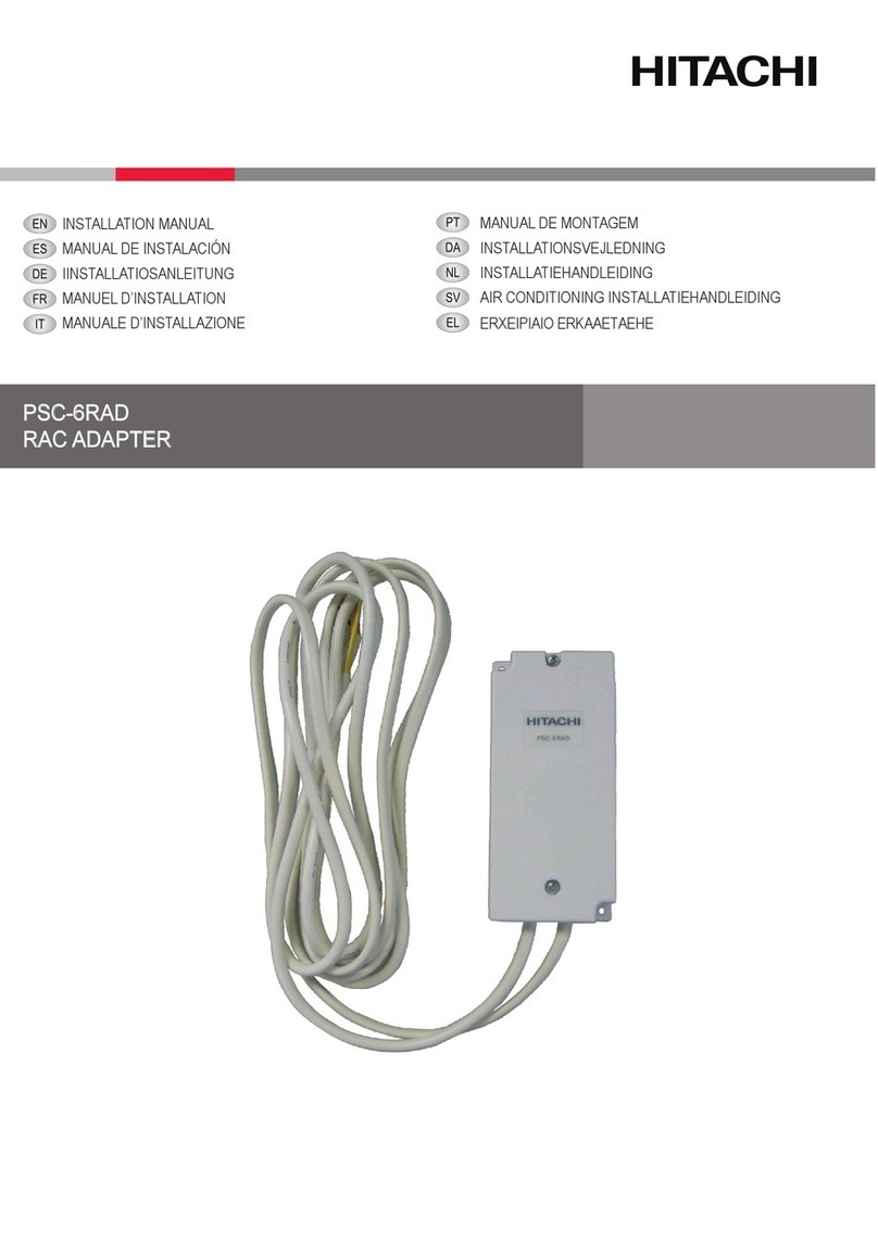
This BMS connection adapter is applied to the packaged air conditioners.
■
Do not place the adapter in a place where flammable gas, or oil mist may stay exit, it
will cause a fire, a fire disaster, deformation of machines, corrosion or breakage.
-
Places where oil mists or steams drifts.
-
Places where sulfide gas form as hot spring drifts.
■
Do not install air conditioner in the following places, it may cause corrosion to the
machine.
-
Places where high in salt contents surrounding as coast regions.
-
Places where with atmosphere of acidity and alkalinity humid place
■
In case of using a medical equipment generating electro-magnetic waves, HARC-BX E
should be installed in an area where free from direct radiation to avoid malfunction of
package air conditioners.
■
In case of using those equipment and radios generating electro-magnetic waves,
HARC-BX E should be placed where a location is at least 3 m away from this
equipment to avoid any radiation transmitting in the air.
■
This interface HARC-BX E must be installed in places free of radio-frequency radiation
because it could cause communications interruptions between the interface and the
upper LON controller.
■
Avoid placing the adapter where exposed to direct sunlight.
1.2. Safety Summary
■
Read and understand this “SAFTETY SUMMARY” before the installation work.
■
The precautions described on this manual are distinguished as “WARNING” and
“CAUTION”. “WARNING” indicates specifically high risk to have serious
consequences caused by the improper installation, which could result in severe
personal injury or death. However, “CAUTION” indicates there is still possibility of risk,
which could result in serious consequences circumstantially. The both precaution signs
contain important description of safety to follow.
■
Conduct test run and check if there are any abnormality after the installation work has
completed.
