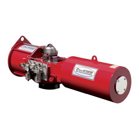
ET Series Heavy-duty Pneumatic Actuators
Installation Operation& Maintenance Manual
Doc No. : HumG-ET-21 E Rev0 Page 10 / 17 Valve Automation Leader, HKC
4. Actuator Disassembly
4.1. General Information
CAUTION:
Turn off all power services before attempting to perform any service on the actuator.
POTENTIAL HIGH PRESSURE VESSEL. Before removing or disassembling your actuator, ensure that the valve or other
actuated devices are isolated and not under pressure.
DANGER:
Before work commences, ensure that explosive and/or noxious gases/liquids are fully vented from the actuator and confirm
the use of appropriate measuring equipment. It is possible that the actuator may contain dangerous gases and/or liquids.
Ensure that all safety measures have been taken to prevent exposure or release of these types of contaminants before
commencing any work. The Actuator Disassembly section has been written to guide through either complete disassembly of
the entire actuator or individual module disassembly as needed (Pneumatic Power Module or Drive module only). Consult
HKC before attempting any potentially dangerous procedures.
Do not remove the Spring Module while the spring is compressed. Follow all instructions written on the warning tag (wired to
the actuator cover)
Where actuators are equipped with a spring cartridge mounted manual override or stroke adjuster, ensure any air or
electrical equipment are moved or isolated and double check that the manual override is set to the auto position.
4.2. Double Acting & Spring Return Actuator Disassembly
4.2.1. Double Acting Actuator Disassembly
CAUTION:
Review the instructions and dangers in section 4.1
For details regarding the '#No' keys, refer to the Bill of Materials in section 2
WARNING:
Ensure that the air supply is isolated and any remaining pressure is vented before disassembly of the actuator.
While removing the yoke shaft pin, care should be taken to avoid dropping it into the cylinder. This may cause damage to
the internal bore coating, and air leakage.
① [Disconnect pneumatic and electric supplies.
② Remove air supply block sets from cylinder unit
③ Remove nuts and washers of the tie rod end from the cylinder unit (No 29,38,39)
④ Remove end cover from the cylinder unit. (No 36)
⑤ Remove cylinder from the body. (No 50)
⑥ Remove rod lock nut and rod washer from piston. (No 33,34)
In case of 635 and over, remove prior to piston guide bar from the piston. (No 28)
⑦ Remove piston from piston rod. (No 27,30)
⑧ Take off rod seal retainer and rod seal from front cover. (No 20,25,23)
⑨ Remove front cover from housing. (No 20, 1)
⑩ Remove position indicator from housing unit, and separate housing cover (No 1, 3, 2)
⑪ Loosen piston rod fixing bolt from slide block and separate piston rod. (No 14, 27)
⑫ Remove guide bar from housing. (No 1,15)
⑬ Pull off yoke and upper bushing from housing. (No 1,6,4,5)
⑭ Pull off lower bushing from housing. (No 1,7,8)
⑮ Remove protection cover from housing which located to opposite side of cylinder. (No 1)
The protection cover is only applied when doesn’t have anything of attachment in opposite side of cylinder.
○
16 Loosen stopper bolts and nuts about 60 mm from housing. (No 1,18,17)
○
17 Disassemble yoke unit
Pull out snap rings (or fixing washers) from both side of slide pin.
Remove slide bearing from the slide pin.
Pull off the slide pin from slide block.
Separate slide block from yoke.--- 18 r0]
4.2.2. Spring Return Actuator Disassembly
CAUTION:
Review the instructions and warnings in section 4.1 before proceeding the disassembly of the Spring Return
type Actuator
DANGER:
Ensure that the air supply is isolated and any remaining pressure is vented before disassembly of the actuator
① Disconnect pneumatic and electric power supplies.
② [Separate between cylinder unit and air supply block (if it were installed).
③ Vent completely remained air from the cylinder.
