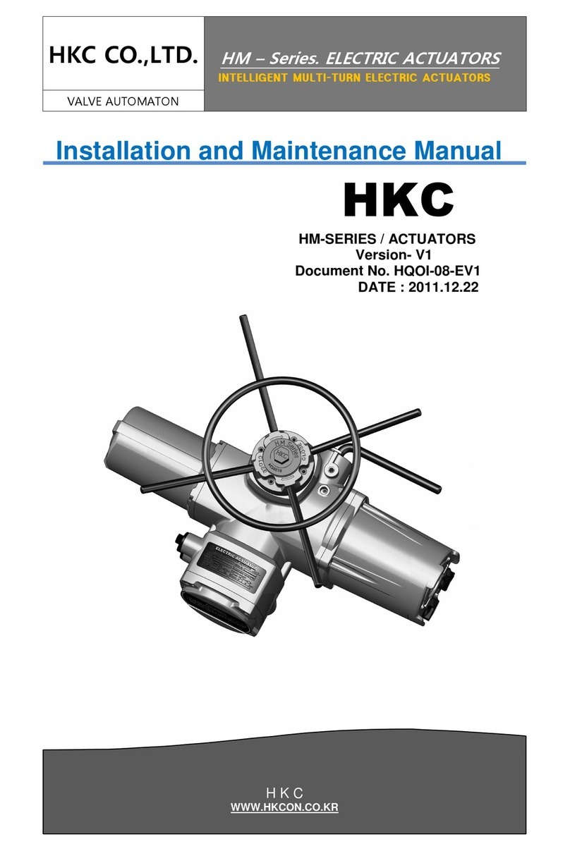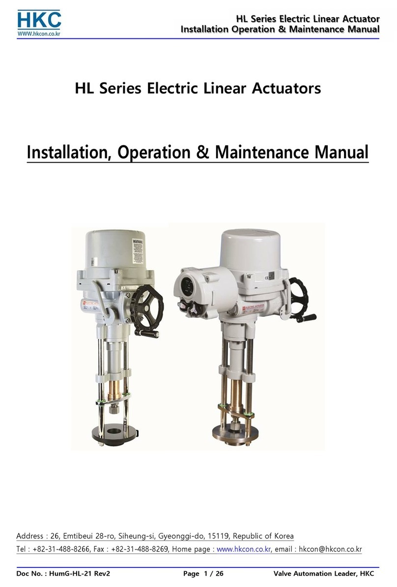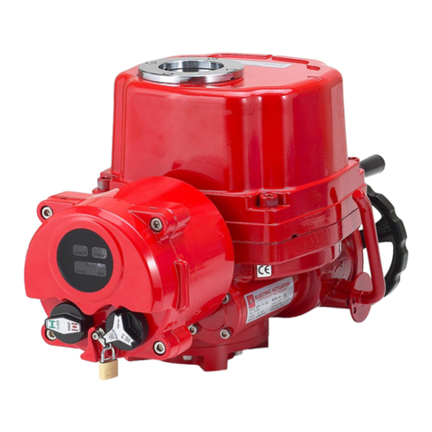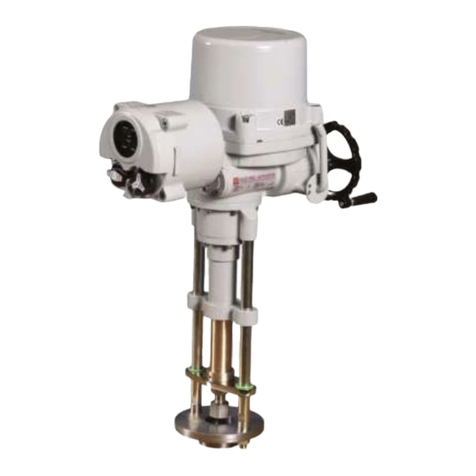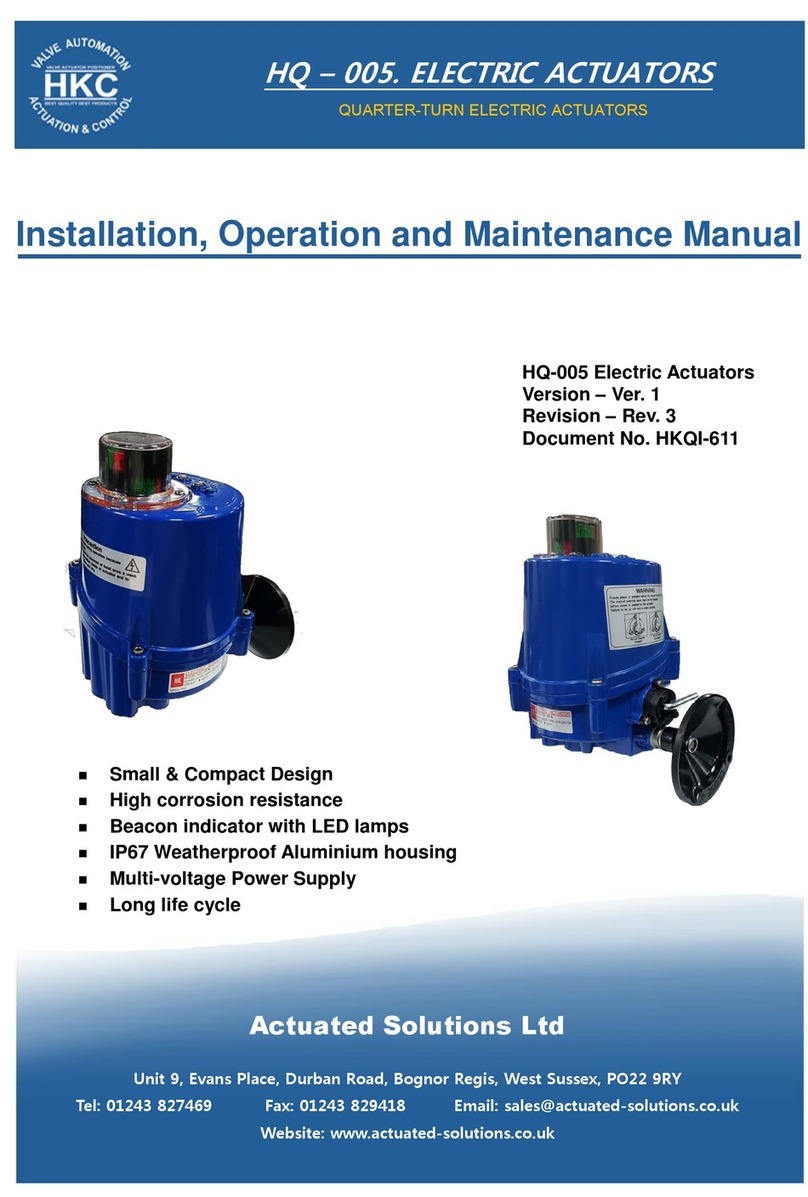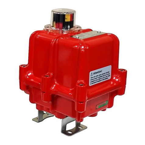
HQ Series Quarter-turn Electric Actuator
Installation Operation& Maintenance Manual
Doc No. : HumG-HQ-21 Rev2 Page 4 / 26 Valve Automation Leader, HKC
2.1.2. Applied Standard
① [IEC60079-0:2011(Ed.6 +IS01, EN60079-0:2012 +A11
② IEC60079-1:2014-06 (Ed.7), EN60079-1:2014
③ IEC60079-31:2013(Ed.2), EN60079-31:2014 ----- 17 Rev0]
2.1.3. Certification
① [IECEx: for HQ-008 ~ HQ-300 with LCU, IECEx DEK 16.0042X
Ex db IIB T4 Gb, Ta -20℃ to +60℃, Ex tb IIIC 135℃ Db
② ATEX: for HQ-008 ~ HQ-300 with LCU, DEKRA 16ATEX0083 X, CE 0344
II 2 G Ex db IIB T4 Gb, Ta -20℃ to +60℃, II 2 D Ex tb IIIC 135℃ Db ----- 18 Rev0]
③ [KCs Ex d IIB T4, -20℃ ~ +60℃:
for HQ-008/010, 제 2020-BO-0016 호, for HQ-015/020, 제 2020-BO-0017 호,
for HQ-030~060, 제 2020-BO-0018 호, for HQ-080~300, 제 2020-BO-0019 호
KCs Ex tD A21 IP6X T135℃, -20℃ ~ +60℃:
for HQ-008/010, 제 2020-BO-0012 호, for HQ-015/020, 제 2020-BO-0013 호,
for HQ-030~060, 제 2020-BO-0014 호, for HQ-080~300, 제 2020-BO-0015 호 – 20 Rev0]
④ CCC: for HQ-008 ~ HQ-300 with LCU, CNEX 2021 3123 0700 0205
Ex d IIB T4 Gb, Ta -20℃ to +60℃, Ex tD A21 IP6X T135℃ ----- 21 Rev2]
[Notes :
Sealing devices must be used and shall be fitted directly at enclosure wall when using conduit.
[Cable glands shall be suitable for the environment and shall be certified as flameproof (Ex db)
and/or dust ignition proof (Ex tb) if used in Zone 1 or Zone 21 application. --- 17 rev 1]
Cable glands and conduit to be installed minimum 6 full threads and the length of thread is
minimum 8mm.
Temperature of cable entry is maximum 100℃. Heat resistance wire is recommended when you
install for flame proof and/or dust ignition proof.
Ex db flame proof and/or dust ignition proof Ex tb certified cable gland shall be used with 100’C
application. --- 17 rev1]
[All information about the material and the allowance of LCU fasteners
Fasteners with yield strength ≥ 210MPa (stainless steel)
Bolts type : M5*0.8, M6*1, M8*1.25, M10*1.5, M12*1.75 (Tolerance Fit 6g) ---17 rev0]
Cable connection : Refers to the Appendix Ⅱ (Wiring Diagram)
For cable entries or conduit entries that are not used, user or installer shall close by certified blanking
elements(stopping plugs) so that the flameproof or dust ignition proof properties of the enclosure
are maintained.
Always ground the enclosure in accordance with local electric codes. The most effective enclosure
grounding method is a direct connection to earth ground with minimal impedance. Methods for
grounding the enclosure include:
Internal ground connection : The internal ground is located in the terminal block #1. Refer to the
enclosed wiring diagram.
External ground connection : The ground lug is located on the center of cable entries.
▶For more information, refer to the Appendix Ⅲ (Grounding) ------- 15 Rev1]
[Stainless steel name plate for the flame proof and dust ignition proof type shall be permanently
attached by rivets or screw on the cover, EAC certified products shall be attached on side of body
using rivets.----- 20 Rev0]
2.2. Initial Inspection
Upon on the receipt of the actuator, the user should inspect the condition of the product and ensure
that product specification stated in the name plate matches with the order sheet.
2.2.1. Remove the packing wrap or wooden box carefully. Inspect the product for any physical damage
that may have occurred during shipment.
2.2.2. Check the product specification with product ordered. If a wrong product has been shipped,
immediately report to our coordinator.
2.3. Storage
Actuators must be stored in a clean, cool and dray area. The unit should be stored with the cover
installed and the cable entry openings sealed. Storage must be off the floor, covered with a sealed dust
protector. When actuators are to be stored outdoor, they must be stored off the ground, high enough to
prevent from being immersed in water or buried in snow.
