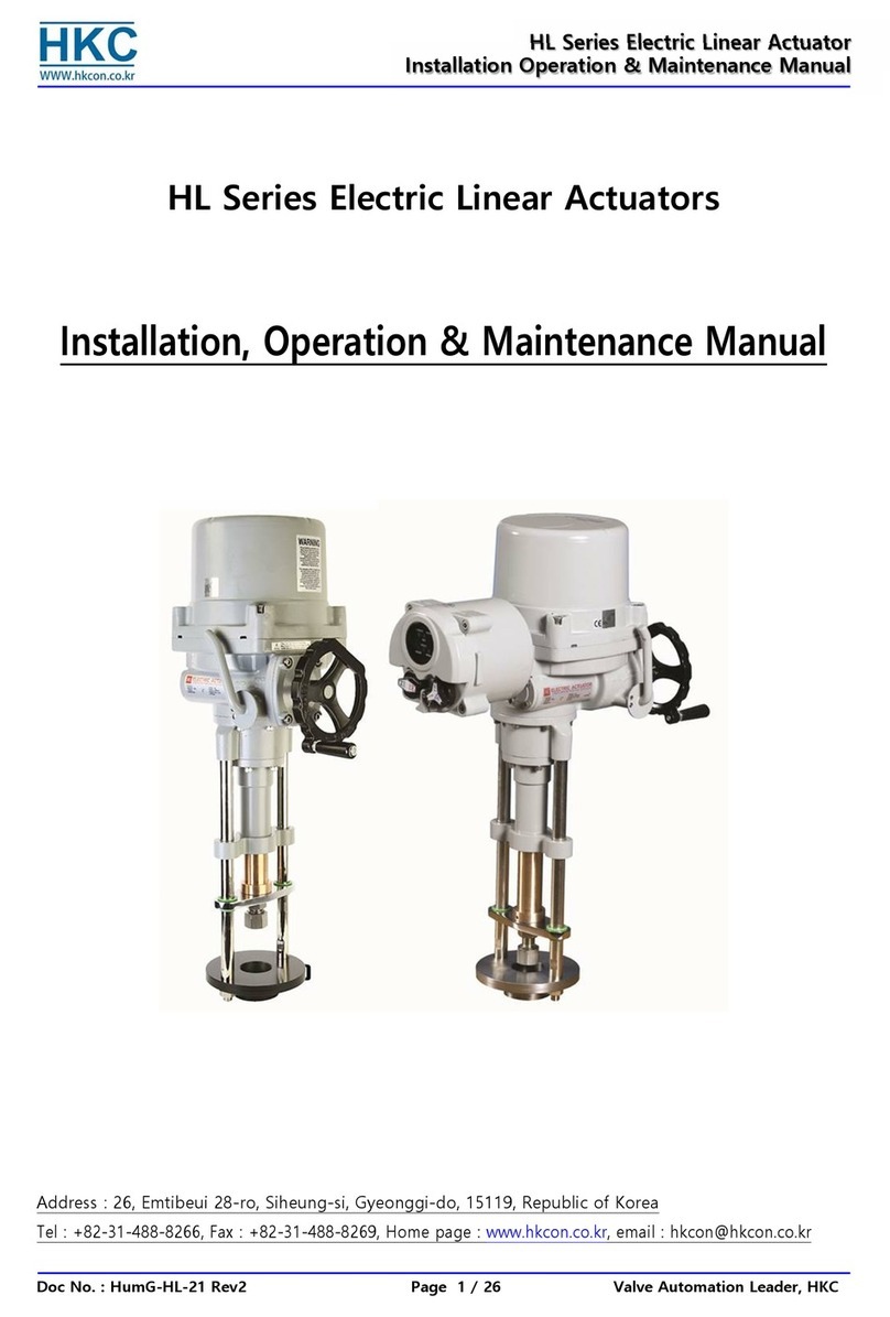
HKC HL Series User manual

H
HL
L-
-S
Se
er
ri
ie
es
s
E
El
le
ec
ct
tr
ri
ic
c
A
Ac
ct
tu
ua
at
to
or
r
I
In
ns
st
ta
al
ll
la
at
ti
io
on
n
a
an
nd
d
O
Op
pe
er
ra
at
ti
io
on
n
M
Ma
an
nu
ua
al
l
H
HK
KC
C
1
Installation & Operation Manual
Doc.No:HKQI-610
Items listed herein were designed , manufactured , delivered in
Electric Actuator HL Series
accordance with contract specifications and quality control system
Edition: 01.2010
Linear Electric Actuator
Installation & Operation Manual
HL Series
Model: HL5KN,7KN,10KN,12KN,15KN,18KN,20KN,25KN
HKC Co., Ltd.
(5Ra - 503, Seonggok-dong), 155, Byeolmang-ro, Danwon-gu, Ansan-si, Gyeonggi-do, Republic of Korea(425-836)

H
HL
L-
-S
Se
er
ri
ie
es
s
E
El
le
ec
ct
tr
ri
ic
c
A
Ac
ct
tu
ua
at
to
or
r
I
In
ns
st
ta
al
ll
la
at
ti
io
on
n
a
an
nd
d
O
Op
pe
er
ra
at
ti
io
on
n
M
Ma
an
nu
ua
al
l
H
HK
KC
C
2
Contents
1. Introduction
1.1 Purpose 5
1.2 Safety Notices 5
2. Product Identification
2.1 Product Identification 5
2.1.1 Marking 5
2.1.2 Certification 6
2.2 Initial Inspection 7
2.3 Storage 7
3. General Information and Features
3.1 General
3.1.1 Performance 8
3.1.2 HL standard technical data 8
3.1.3 HL technical data 9
3.1.4 Duty cycle 9
3.1.5 Heater 9
3.1.6 Hand wheel and declutching 10
3.1.7 Lubrication 10
3.2 External parts for standard models
3.2.1 HL-5,7,10,12,15,18,20,25KN 10
3.3 Internal parts for standard models 11
4. Installation instruction
4.1 Pre-installation for use in general service 12
/ potentially explosive atmosphere
4.2 Actuator mounting 12
4.2.1 Actuator mounting details 13
4.2.2 Preparing assembly 14
4.3 Limit switch setting 15
4.4 Force switch setting 16
4.5 Position feedback potentiometer 16
4.5.1 Calibration potentiometer 17
4.6 Proportional Control Unit –PCU (option) 18
4.6.1.Check point before using actuator
4.6.2.General 19
4.6.3.Standard specification 19
4.6.4 Function of PCU and how to set and to use it 20

H
HL
L-
-S
Se
er
ri
ie
es
s
E
El
le
ec
ct
tr
ri
ic
c
A
Ac
ct
tu
ua
at
to
or
r
I
In
ns
st
ta
al
ll
la
at
ti
io
on
n
a
an
nd
d
O
Op
pe
er
ra
at
ti
io
on
n
M
Ma
an
nu
ua
al
l
H
HK
KC
C
3
Select Input signal
Set DIP switch for fail position
Delay time
Resolution Adjustment
Manual operation
Special setting for full open and close
Auto-setting
Split range (CH1)
Reversal acting switch (CH2)
Select output signal
4.6.5 Check operation of PCU
4.6.6 Layout of PCU 24
4.6.7 Layout of PCU Card
4.7 Position feedback potentiometer-CPT 26
4.7.1 Standard features
4.7.2 Calibration zero span
5. Operation instruction
5.1 Electrical connections and preliminary test 27
5.2 Wiring diameters for standard models 28
5.2.1 On/off type
5.2.2 PCU type 29
6. Maintenance
6.1 Maintenance 30
6.2 Tools 31
7 Dimensions for actuator
7.1 5KN,7KN(ON/OFF type) 32
7.2 5KN,7KN(Control type) 33
7.3 10KN,12KN,15KN(ON/OFF type) 34
7.4 10KN,12KN,15KN (Control type) 35
7.5 18KN,20KN,25KN(ON/OFF type) 36
7.6 18KN,20KN,25KN (Control type) 37
8. Trouble shooting 38
9. Installation and maintenance tips 39
10.Grounding
Appendix Ⅰ: HL series coding system 40
HL-5KN abcdefg 41
HL-7KN abcdefg 42
HL-10KN abcdefg 43
HL-12KN abcdefg 44

H
HL
L-
-S
Se
er
ri
ie
es
s
E
El
le
ec
ct
tr
ri
ic
c
A
Ac
ct
tu
ua
at
to
or
r
I
In
ns
st
ta
al
ll
la
at
ti
io
on
n
a
an
nd
d
O
Op
pe
er
ra
at
ti
io
on
n
M
Ma
an
nu
ua
al
l
H
HK
KC
C
4
HL-15KN abcdefg 45
HL-18KN abcdefg 46
HL-20KN abcdefg 47
HL-25KN abcdefg 48
Explosion proof type actuator 49

H
HL
L-
-S
Se
er
ri
ie
es
s
E
El
le
ec
ct
tr
ri
ic
c
A
Ac
ct
tu
ua
at
to
or
r
I
In
ns
st
ta
al
ll
la
at
ti
io
on
n
a
an
nd
d
O
Op
pe
er
ra
at
ti
io
on
n
M
Ma
an
nu
ua
al
l
H
HK
KC
C
5
1 Introduction
1.1 Purpose
This Installation and operating manual explains how to install, operate and maintain HL electric actuators.
1.2 Safety Notices
Safety notices in this manual detail precautions the user must take to reduce the risk of personal injury and damage to the
equipment. User must read these instructions before installation, operating, or maintenance.
DANGER : Refers to personal safety. Alerts the user to danger or harm.
The hazard or unsafe practice will result in severe injury or death.
WARNING : Refers to personal safety. Alerts the user to potential danger.
Failure to follow warning notices could result in personal injury or death.
CAUTION : Directs the user’s attention to general precautions that, if not followed,
could result in personal injury and/or equipment damage.
Note : Highlights information critical to the user’s understanding of the actuator’s installation and operation.
2 Product Identification
2.1 Product Identification
The actuator name plate is located on the side of the opposite the conduit entry. The name plate contains the following
2.1.1 Marking
a) General
HL logo(trade mark)
Electrical power supply
Model
Type
Rated current
Operating time(seconds)
Serial No.
Option

H
HL
L-
-S
Se
er
ri
ie
es
s
E
El
le
ec
ct
tr
ri
ic
c
A
Ac
ct
tu
ua
at
to
or
r
I
In
ns
st
ta
al
ll
la
at
ti
io
on
n
a
an
nd
d
O
Op
pe
er
ra
at
ti
io
on
n
M
Ma
an
nu
ua
al
l
H
HK
KC
C
6
Name of manufacturer and country shall not be printed based on OEM.
b) Explosion proof
HKC logo
Model
Motor spec.
Electrical power supply
Ambient temperature
KTL cert. No.
Serial No.
Manufacturer’s address
Warning
Applied standards : EN50014 / EN50018
2.1.2 Certification (pended)
a) KTL (Korea Testing Laboratory)
HL-5KN
Cert.No. : 1454-051
IP68
Applied Standard : KS C IEC 60529(2002) & IEC 60529(2001)
HL-7KN
Cert.No. : 1454-165
IP68
Applied Standard : KS C IEC 60529(2002) & IEC 60529(2001)
HL-10KN
Cert.No. : 1454-255
IP68
Applied Standard : KS C IEC 60529(2002) & IEC 60529(2001)
HL-12KN
Cert.No. : 1471-272
IP68
Applied Standard : KS C IEC 60529(2002) & IEC 60529(2001)
HL-15KN
Cert.No. : 1454-051
IP68
Applied Standard : KS C IEC 60529(2002) & IEC 60529(2001)
HL-18KN
Cert.No. : 1454-165
IP68
Applied Standard : KS C IEC 60529(2002) & IEC 60529(2001)
ELECTRIC ACTUATOR
L I N E A R M O T I O N E L E C T R I C A C T UAT O R
POWER:
STROKE: Max mm
FORCE: N
SERIAL NO:
MODEL:HL-
RATED CURRENT: A
OPERATION TIME: mm/SEC
OPTION::

H
HL
L-
-S
Se
er
ri
ie
es
s
E
El
le
ec
ct
tr
ri
ic
c
A
Ac
ct
tu
ua
at
to
or
r
I
In
ns
st
ta
al
ll
la
at
ti
io
on
n
a
an
nd
d
O
Op
pe
er
ra
at
ti
io
on
n
M
Ma
an
nu
ua
al
l
H
HK
KC
C
7
HL-20KN
Cert.No. : 1454-255
IP68
Applied Standard : KS C IEC 60529(2002) & IEC 60529(2001)
HL-25KN
Cert.No. : 1471-272
IP68
Applied Standard : KS C IEC 60529(2002) & IEC 60529(2001)
NOTE :
Sealing devices must be used and shall be fitted directly at enclosure wall when using conduit.
Cable glands shall be suitable for the environment and shall be certified as flameproof if used in Zone 1
application.
Cable glands and conduit to be installed minimum 6 full threads and the length of thread is minimum 8mm.
Temperature of cable entry is maximum 100℃. Heat resistance wire is recommended when you install.
Cable connection : Refers to theAppendix Ⅱ(Wiring Diagram)
For cable entries or conduit entries that are not used, user or installer shall close by certified blanking
elements(stopping plugs) so that the flameproof properties of the enclosure are maintained.
Always ground the enclosure in accordance with local electric codes. The most effective enclosure
grounding method is a direct connection to earth ground with minimal impedance. Methods for grounding
the enclosure include:
Internal ground connection : The internal ground is located in the terminal block #1. Refers to the enclosed
wiring diagram.
External ground connection : The ground lug is located on the centre of cable
entries.
▶More information, refers to the Appendix Ⅲ(Grounding)
2.2 Initial inspection
When the user receipt the actuator, inspect the condition of the product and ensure the name plate comparing with order
sheet.
Remove packing wrap or wooden box carefully. Inspect the product for any physical damage that may have
occurred during shipment.
Check the product specification with product ordered. If a wrong product have been shipped, immediately
report to our coordinator.
2.3 Storage
Actuators must be stored in a clean, cool and dry area. The unit shall be stored with the cover installed and the conduit
openings sealed. Storage must be off the floor, covered with a sealed dust protector.
When actuators be stored outdoor, they must be stored off the ground, high enough to prevent being immersed in water
or buried in snow.
3 General Information and Features
3.1 General
HKC HL series electric actuators are designed for the operation of industrial valves, e.g. globe valves and gate valves.
Actuator force ranges from 5000n to 25,000Nm, currently eleven models are available:
HL-5KN, 7KN, 10KN, 12KN, 15 KN, 18KN, 20KN, 25KN
H
HL
L-
-S
Se
er
ri
ie
es
s
E
El
le
ec
ct
tr
ri
ic
c
A
Ac
ct
tu
ua
at
to
or
r
I
In
ns
st
ta
al
ll
la
at
ti
io
on
n
a
an
nd
d
O
Op
pe
er
ra
at
ti
io
on
n
M
Ma
an
nu
ua
al
l
H
HK
KC
C
8
3.1.1 Performance
Type
Max.
output
force
Operating
time(mm/s
ec.)
Max.
Stroke
Duty
cycle
Rated current(A) 50/60Hz
Number
of
handle
turn
Weig
ht
IEC34-1
1 Phase
3 Phase
k N
50/60HZ
mm
S4(%)
110 V
220 V
220 V
380 V
440 V
460 V
N
kg
HL-5KN
5
0.44/0.53
60
50
0.96/0.97
0.47/0.46
N/A
0.42/0.33
0.57/0.43
N/A
227
11
HL-7KN
7
0.44/0.53
60
50
0.96/0.97
0.47/0.46
N/A
0.42/0.33
0.57/0.43
N/A
227
11
HL-10KN
10
0.69/0.82
70
50
1.51/1.62
0.72/0.84
0.69/0.50
0.35/0.27
0.55/0.34
0.23/0.19
184
21
HL-12KN
12
0.69/0.82
70
50
1.51/1.62
0.72/0.84
0.69/0.50
0.35/0.27
0.55/0.34
0.23/0.19
184
21
HL-15KN
15
0.69/0.82
80
50
1.51/1.62
0.72/0.84
0.69/0.50
0.35/0.27
0.55/0.34
0.23/0.19
210
21
HL-18KN
18
0.69/0.83
100
50
1.37/1.67
0.68/0.81
0.49/0.41
0.33/0.27
0.43/0.30
0.27/0.24
260
33
HL-20KN
20
0.69/0.83
100
50
4.27/3.56
1.37/1.27
0.86/0.72
0.51/0.42
0.66/0.46
0.44/0.32
260
33
HL-25KN
25
0.69/0.83
100
50
4.27/3.56
1.37/1.27
0.86/0.72
0.51/0.42
0.66/0.46
0.44/0.32
260
33
3.1.2 HL Standard Technical Data (optional)
Enclosure Rated Weatherproof IP67, NEMA 4 & 6
Enclosure High grade aluminium alloy, corrosion coated
Power Supply 110 / 220 VAC 1 Ph, 220 / 380 / 440 / 460 VAC 3 Ph, 24 VDC 50/60Hz
Duty type 1) S4 50% / S2 30min (IEC 60034)
Motor reversible motor
Limit Switches 2 x open/close SPDT, 250 VAC 16A rating
Auxiliary Limit Switches 2 x open/close SPDT, 250 VAC 16A rating (except HL5~15KN)
Force Switches Open/close SPDT, 250VAC 10A
Stall Protection Built –in thermal protection
Travel Angle 90 degree +/- 10%
Indicator Continuous position indicator
Manual Override Declutchable manual override
Self Locking By means of TM Screw(KSB0227)
Space Heater 2W ceramic housed
Conduit Entries 2 x PF3/4” , M20 or G 3/4 for EXA
Lubrication Grease moly EP
Ambient Temperature -20 deg C ~ + 80 dec C (except on CPT & PCU board )
External Coating Dry powder polyester
3.1.3 HL Option Technical Data (optional)
EXA Explosion proof enclosure (EEx d II B T4 IP67)
WTA Watertight enclosure (IP68 10m / 72hr)
PIU Potentiometer unit (0~1KΩ)
PCU Proportional control unit (input,output 0~10 VDC, 4~20mA DC)
SICU Semi-Integral control unit(LCU+IMS+phase protect indicator)
ICU Intelligent Digital control unit(LCU+IMS+auto phase discriminator)
CPT Current position transmitter(output 4~20mA DC)
ALS Additional limit switches (SPDT X 2EA 250 VAC 16A Rating)
FPA1 Fire proofing actuator 1050° ± 5° / 50min
FPA2 Fire proofing actuator 250° ± 5° / 150min
Note : 1)based on 20°C ambient temperature
See Appendix Ⅰ.

H
HL
L-
-S
Se
er
ri
ie
es
s
E
El
le
ec
ct
tr
ri
ic
c
A
Ac
ct
tu
ua
at
to
or
r
I
In
ns
st
ta
al
ll
la
at
ti
io
on
n
a
an
nd
d
O
Op
pe
er
ra
at
ti
io
on
n
M
Ma
an
nu
ua
al
l
H
HK
KC
C
9
3.1.4 Duty Cycle *1
Duty cycle rated IEC60034 –S4 50% / S2 30min
Exceeding the actuator’s rated duty cycle may cause thermal overload.
Note *1
Type of duty according to VDE 0530 / IEC 60034-1
3.1.5 Heater
Condensation in the actuator is possible due to wide fluctuation of the ambient temperature. The heater integrated in the
control unit prevents this in general.
2W, Ceramic housing with thermostat to prevent over heating with 60℃set temperature
Heating element Self-regulating
Voltage ranges 110 V 2W 12KΩJ
(based on control power) 220 V 2W 30KΩJ
24 VDC 2W 470ΩJ
3.1.6 Hand wheel and Declutching
HL actuators are provided a declutchable manual override system.
In order to manually operate the actuator, pull the manual override
engagement lever towards the hand wheel until it remains in position.
Turn the hand wheel until the valve reaches the required position
Turn clockwise to close(down) and counter-clockwise to open(up)
open(up)
close(down)
AUTO HAND
Note ;
The override engagement lever returns automatically to auto position when the actuator is
operated electrically.
Short –time duty S2
Intermittent duty S4
The operation time at a constant load is short,
so that thermal equilibrium is not reached. The
pause is long enough for the machine to cool
down to ambient temperature. The duration of
the short –time operation is limited to 15min
(10min, 30min)
The duty is a sequence of identical cycles
which consist of starting time, operation time
with constant load and rest period. The rest
period allows the machine to cool down so
that thermal equilibrium is not reached. The
relative on-time at S4-25% or S4-50% is
limited to 25% and 50% respectively.

H
HL
L-
-S
Se
er
ri
ie
es
s
E
El
le
ec
ct
tr
ri
ic
c
A
Ac
ct
tu
ua
at
to
or
r
I
In
ns
st
ta
al
ll
la
at
ti
io
on
n
a
an
nd
d
O
Op
pe
er
ra
at
ti
io
on
n
M
Ma
an
nu
ua
al
l
H
HK
KC
C
10
3.1.7 Lubrication
HL is a totally enclosed unit with a permanently lubricated gear train (Moly EP Grease). Once installed lubrication should
not be required. However, periodic preventative maintenance will extend the operating life of the actuator.
3.2 External Parts for Standard Models
3.2.1 HL 5,7,10,12,15,18,20,25KN
①
④
⑤
②⑥
③
⑦
⑧
⑨
⑩
⑪
OPTION: LCU UNIT
⑫⑬
OPTION: Driving rod rubber
⑭
External Parts
HL SERIES
1
Top Cover
2
Body
3
Auto & manual Lever
4
Cover bolt
5
Conduit Entries (PF 3/4”)x2
6
Hand wheel
7
Upper Base
8
Bridge Base
9
Guide rod
10
Rod Holder
11
Driving rod
12
Locking plate
13
Union joint & nut
14
Guide rod nut

H
HL
L-
-S
Se
er
ri
ie
es
s
E
El
le
ec
ct
tr
ri
ic
c
A
Ac
ct
tu
ua
at
to
or
r
I
In
ns
st
ta
al
ll
la
at
ti
io
on
n
a
an
nd
d
O
Op
pe
er
ra
at
ti
io
on
n
M
Ma
an
nu
ua
al
l
H
HK
KC
C
11
3.3 Internal Parts for Standard Models
⑥
⑦
⑧
①
②
③
④
⑤
⑨
⑩
Internal Parts
HL SERIES
1
Motor
2
Potentiometer
3
Terminal
4
Open force switch
(RED Color)
5
Close force switch
(BLUE Color)
6
Close limit switch
7
Open limit switch
8
Capacitor
9
PCU Board
10
Heater

H
HL
L-
-S
Se
er
ri
ie
es
s
E
El
le
ec
ct
tr
ri
ic
c
A
Ac
ct
tu
ua
at
to
or
r
I
In
ns
st
ta
al
ll
la
at
ti
io
on
n
a
an
nd
d
O
Op
pe
er
ra
at
ti
io
on
n
M
Ma
an
nu
ua
al
l
H
HK
KC
C
12
4 Installation Instruction
4.1 Pre-Installation for
use in general service
Verify the actuators nameplate to insure correct model number, force, operating speed, voltage and enclosure type before
installation or use.
It is important to verify that the output force of the actuator is appropriate for the force requirements of the valve and that
the actuator duty cycle is appropriate of the intended application.
use in potentially explosive atmosphere
Model HL - . . . 1 . 0 . . . 0 1)
Type of enclosure II 2G EEx d IIB T4
Ambient temperature -20 deg C ~ + 80 dec C
Installation, commissioning, maintenance, repairs and modification work must only be performed by qualified personnel
with extensive knowledge on how to work on explosion-proof electrical equipment.
Note : 1) Further information should be use of the HL electric actuator catalogue.
Refers to the Cl.2.2 this manual.
Warning :
Read this installation and maintenance manual carefully and completely before attempting to install,
operate, or troubleshoot the HKC actuator.
4.2 Actuator Mounting
Note :
Prior to mounting the part-turn actuator must be checked for any damage.
Damaged parts must be replaced by original spare parts.
Mounting is most easily done with the valve shaft pointing vertically upward. But mounting is also possible in any other
position.
The actuator may be mounted in any position
The HL- Series actuators are supplied with a Union joint & nut.
The actuator Union joint is removable for ease of machining.
Caution ;
Do not attempt to work on your HKC actuator without first shutting off incoming power.
Do not attach ropes or hooks to the hand wheel for the purpose of lifting by hoist.

H
HL
L-
-S
Se
er
ri
ie
es
s
E
El
le
ec
ct
tr
ri
ic
c
A
Ac
ct
tu
ua
at
to
or
r
I
In
ns
st
ta
al
ll
la
at
ti
io
on
n
a
an
nd
d
O
Op
pe
er
ra
at
ti
io
on
n
M
Ma
an
nu
ua
al
l
H
HK
KC
C
13
4.2.1 Actuator Mounting Details
If the linear actuator and the valve are supplied separately you will have to mount the linear actuator on the valve.
Union nut
Joint ring
Guide rod nut(2ea)

H
HL
L-
-S
Se
er
ri
ie
es
s
E
El
le
ec
ct
tr
ri
ic
c
A
Ac
ct
tu
ua
at
to
or
r
I
In
ns
st
ta
al
ll
la
at
ti
io
on
n
a
an
nd
d
O
Op
pe
er
ra
at
ti
io
on
n
M
Ma
an
nu
ua
al
l
H
HK
KC
C
14
4.2.2 Preparing assembly
Warning : A non-attached valve causes damage!
If you operate the linear actuator without valve, the spindle nut may fall off due to the missing stop.
ATTENTION • Always operate the linear actuator with a valve attached.
Allow for about 200 mm space above the cover at the site of installation. Check the working environment before
assembling and commissioning the linear actuator. Ensure that the valve is correctly fitted. For details please see
assembly instructions for valve. Determine the assembly position of the linear actuator. Do not arrange linear actuators
in a hanging position.
A
B
Assembly positions for linear actuator and valve

H
HL
L-
-S
Se
er
ri
ie
es
s
E
El
le
ec
ct
tr
ri
ic
c
A
Ac
ct
tu
ua
at
to
or
r
I
In
ns
st
ta
al
ll
la
at
ti
io
on
n
a
an
nd
d
O
Op
pe
er
ra
at
ti
io
on
n
M
Ma
an
nu
ua
al
l
H
HK
KC
C
15
4.3 Limit Switch Setting
Rotate the actuator hand wheel manually to closed position
Using a hex wrench, loosen the set screw in the CLOSE limit switch cam
Rotate the CLOSE cam towards CW limit switch lever until the switch ‘clicks’ (Fig 1)
Tighten the set screw with hex wrench
Rotate the actuator hand wheel manually to open position
Using a hex wrench, loosen the set screw in the OPEN limit switch cam
Rotate the OPEN can towards CCW limit switch lever until the switch ‘clicks’ (Fig 2)
Tighten set screw with hex wrench
Danger :
HAZARDOUS VOLTAGE. Make sure all power is disconnected before making the setting.
Fig.1 Close Cam Setting
Close limit switch
Close limit switch cam (clockwise)
2mm hexagon socket screw key
Fig.2 Open Cam Setting
2mm hexagon socket screw key
Open limit switch
Open limit switch cam (counterclockwise)

H
HL
L-
-S
Se
er
ri
ie
es
s
E
El
le
ec
ct
tr
ri
ic
c
A
Ac
ct
tu
ua
at
to
or
r
I
In
ns
st
ta
al
ll
la
at
ti
io
on
n
a
an
nd
d
O
Op
pe
er
ra
at
ti
io
on
n
M
Ma
an
nu
ua
al
l
H
HK
KC
C
16
4.4 Force Switch Setting
Force spring which detects the variation of force during operation is installed for preventing damage of valve and actuator
under overload condition. Once actuator is under overload, force switch is tripped and actuator stoped immediately.
The force switches are set by manufacturer on the production site basically.
Re-setting be necessary, please contact the HKC service or representative before setting.
Caution ;
Do not reset force switch to a setting higher than the maximum recommended by the manufacturer.
Open force switch & cam(RED Color)
Close force switch & cam (BLUE Color)
4.5 Position Feedback Potentiometer (Optional)
4.5.1 Calibration Potentiometer
The potentiometer has been calibrated at the factory. However, if re-calibration is required, proceed as follows:
Apply power (or use manual override) to drive the actuator to its true closed position (clockwise rotation).
Connect an ohmmeter to P1 (red) and P3 ( black ) resistance should be approximately 1000ohms
Put actuator full close(down) position.
Loosen the point shaft gear and connect the ohmmeter to P1 (red) and P2 (white) and gently rotate until a reading
of 80-120Ωis achieved (100 ohms preferred).
{Full close range: 0~100ΩFull open range:700~900Ω}
While maintaining this reading tighten the point gear set screw with an hex wrench(HL5,7KN).
Engage potentiometer spring between gear and pointer shaft (refer diagram B)

H
HL
L-
-S
Se
er
ri
ie
es
s
E
El
le
ec
ct
tr
ri
ic
c
A
Ac
ct
tu
ua
at
to
or
r
I
In
ns
st
ta
al
ll
la
at
ti
io
on
n
a
an
nd
d
O
Op
pe
er
ra
at
ti
io
on
n
M
Ma
an
nu
ua
al
l
H
HK
KC
C
17
HL 10,12,15,18,20,25KN
Open(up)100% →1kΩClose(down) 0% →0Ω
HL 5,7KN
:Close(down) 0% →0Ω
:Open(up)100% →1kΩ
*Tighten the point gear set screw with an hex wrench.(HL5,7KN)

H
HL
L-
-S
Se
er
ri
ie
es
s
E
El
le
ec
ct
tr
ri
ic
c
A
Ac
ct
tu
ua
at
to
or
r
I
In
ns
st
ta
al
ll
la
at
ti
io
on
n
a
an
nd
d
O
Op
pe
er
ra
at
ti
io
on
n
M
Ma
an
nu
ua
al
l
H
HK
KC
C
18
Fix potentiometer by placing spring as per diagram A (HL 10,12,15,18,20,25KN)
Diagram B (HL 5,7KN)

H
HL
L-
-S
Se
er
ri
ie
es
s
E
El
le
ec
ct
tr
ri
ic
c
A
Ac
ct
tu
ua
at
to
or
r
I
In
ns
st
ta
al
ll
la
at
ti
io
on
n
a
an
nd
d
O
Op
pe
er
ra
at
ti
io
on
n
M
Ma
an
nu
ua
al
l
H
HK
KC
C
19
4.6 Proportional Control Unit –PCU (option)
*Thanks for purchasing our Hl series electric actuator.
Before installing or operating actuator, please read to this manual to know thoroughly
how to install or operator. The contents in this manual is subject to change due to the quality improvement without
individual notice.
4.6.1 Check point before using actuator
1)Check if specification (Model No, Main Power, Control Power, Options) of delivered actuator meets your
requirement or not.
2) Check the application such as valve, Damper & etc.
3) Check if mounting of actuator on application is correct
and tight enough.
4) Check if settings of actuator such as limit switch, stopper bolts, indicator is correct or not.
5) Check if electric wiring is correct or not.
6) In case of 3 phase motor, check rotating direction.
☞Check rotating direction of actuator Open actuator about 50% by manual, supply power to
actuator for 2~3 second. Push close button and check if actuator move close direction or not.
If yes, it is O.K, but reverse, stop to supply power to actuator and change the 2 power lines each
other among 3 lines.
7)Generally all function of PCU is set by factory before delivery and no need to set the functions again.
Only in case that customer wants to adjust the limit switches, to set the function of PUC is required.
Setting is so simple and customer just pushes the AUTO SETTING button after putting actuator about
50% open (or close) position. PCU automatically accomplishes to set all the functions by itself.
8)Disassembly, modification without factory’s consent may affect the performance of the actuator.

H
HL
L-
-S
Se
er
ri
ie
es
s
E
El
le
ec
ct
tr
ri
ic
c
A
Ac
ct
tu
ua
at
to
or
r
I
In
ns
st
ta
al
ll
la
at
ti
io
on
n
a
an
nd
d
O
Op
pe
er
ra
at
ti
io
on
n
M
Ma
an
nu
ua
al
l
H
HK
KC
C
20
4.6.2 General performance
PCU is the local actuator controller, using 12bit A/D converter and 8 bits Microprocessor, which operate actuator to open
and close according to the input signal from main controller. After operating actuator, detect the current position of actuator
and transmit feedback output signal about current position to the main controller.
4.6.3 Standard specification
Model: PCU REV 3.1
Model: 85V~280VAC ±10% 50/60Hz 4VA Max (NEW Wide range of voltage)
Input signal: 4~20mA DC, 2~10VDC, 0~5VDC, 0~10VDC, 1~5VDC Input resistance: 250 Ohm,
Feedback signal: 100 ~10Kohm Exaction: 2.3VDC
Output signal: 4~20mA DC, 2~10VDC, 0~5VDC, 0~10VDC, 1~5VDC
Load resistance: 750Ohm Max.
Control output : Relay contact 250VAC 10A Max (Inductive load)
Number of output contact: 2 ea (Open and close contact)
Delay time adjustment: 0 ~7.5 sec (1Step 0.5sec 0‾15Step)
Dead band adjustment: 0.1 ~ 4.5%
Resolution: Min. 1/1000
Position conversation accuracy : ±0.5 ~ ±1.5%(Depends on installation)
Ambient temperature: -10oC ~ +70oC
Ambient humidity: 90% RH Max (Non-condensate)
Dielectric strength: 1500V AC 1Min (Input to output, Power to Ground)
Insulation resistance: Min. 500VDC 30Mohm
Vibration & Shock (X, Y, Z): 6g based on RMF, Frequency: 0.2 ~ 34Hz, 30Min
LED signal
LED
SIGNAL
View A
Blue on
Power on(AUTO)
Blue Flicker
AUTO SETTING
Green on
Close
Red on
Open
Yellow on
Manual OPN.by card
Yellow Flicker
Fault in either Wrong
input wiring, Wrong
PIU setting No input
signal,
Other manuals for HL Series
1
This manual suits for next models
8
Table of contents
Other HKC Controllers manuals

HKC
HKC HQ-005 RBP Instruction manual

HKC
HKC HQ Series Instruction manual

HKC
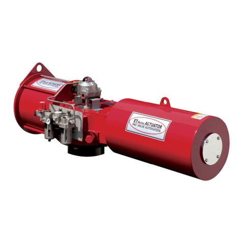
HKC ET Series Instruction manual

HKC
HKC HP Series Instruction manual

HKC
HKC HQ Series Instruction manual

HKC
HKC HL Series Instruction manual

HKC
HKC HQ-005 User manual

HKC
HKC ET Series Instruction manual

HKC
HKC HQ-004 Instruction manual

HKC
HKC HQ-006 Instruction manual