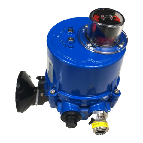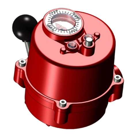
HQ-006 Quarter-turn Electric Actuator
Installation Operation& Maintenance Manual
Doc No. : HumA-HQ006-21 Rev1 Page 2 / 22 Valve Automation Leader, HKC
Contents
1. Introduction ................................................................................................................. 3
1.1. Purpose ............................................................................................................................................... 3
1.2. Safety Notices .................................................................................................................................... 3
2. Product Identification ................................................................................................. 3
2.1. Product Identification ...................................................................................................................... 3
2.2. Initial Inspection ............................................................................................................................... 3
2.3. Storage ................................................................................................................................................ 4
3. General Information and Features ............................................................................ 4
3.1. General Information ......................................................................................................................... 4
3.2. External Parts for Standard Models .............................................................................................. 5
3.3. Internal Parts for Standard Models............................................................................................... 5
4. Installation ................................................................................................................... 6
4.1. Pre-installation .................................................................................................................................. 6
4.2. Actuator Mounting ........................................................................................................................... 6
4.3. Limit Switch Setting ......................................................................................................................... 7
4.4. Setting Potentiometer (Replacement and Setting) .................................................................... 8
4.5. Current Position Transmitter – CPT (Optional) ........................................................................... 8
4.6. Proportional Control Unit ............................................................................................................. 10
4.7. AC/DC Multi-Board ......................................................................................................................... 16
5. Operation ................................................................................................................... 16
5.1. Electrical Connections and Preliminary Test.............................................................................. 16
5.2. Wiring Diagrams for Standard Models ...................................................................................... 18
5.2.1. HQ-006 On/Off type ......................................................................................................... 18
5.2.2. HQ-006 PCU type .............................................................................................................. 18
6. Maintenance .............................................................................................................. 19
6.1. Maintenance .................................................................................................................................... 19
6.2. Tools .................................................................................................................................................. 19
7. Trouble Shooting ....................................................................................................... 19
7.1. The actuator does not respond ................................................................................................... 20
7.2. The actuator is supplied with power but does not operate .................................................. 20
7.3. Actuator runs erratically ................................................................................................................ 20
7.4. Optional Equipment(s) ................................................................................................................... 20
8. Dimensions ................................................................................................................ 21
