Hobo RX User manual

HOBO® RX Wireless Sensor Network
RXW Davis® 0.01" or 0.2 mm Rain Gauge Sensor (RXW-RGx-xxx) Manual
22244-2
This sensor measures rainfall and is designed to work with the HOBO RX Wireless Sensor
Network in which data is transmitted wirelessly from the sensor mote across the network to
the RX3000 station and then uploaded to HOBOlink® web-based software. With HOBOlink, you
can monitor sensor readings, view graphs, set up alarms, download data, and more.
Specifications
Sensor
Measurement Range 0 to 10.2 cm (0 to 4 in.) per hour, maximum 4,000 tips per logging interval
Accuracy ±4.0%, ±1 rainfall count between 0.2 and 50.0 mm (0.01 and 2.0 in.) per
hour; ±5.0%, ±1 rainfall count between 50.0 and 100.0 mm (2.0 and 4.0 in.)
per hour
Resolution 0.01 in. (RXW-RGE-xxx) or 0.2 mm (RXW-RGF-xxx)
Calibration Requires annual calibration; can be field calibrated
W
ireless Mote
O
perating Temperature
Range
Mote: -25° to 60°C (-13° to 140°F) with rechargeable batteries
-40 to 70°C (-40 to 158°F) with lithium batteries
Radio Power 12.6 mW (+11 dBm) non-adjustable
Transmission Range At least 304.8 m (1,000 ft) line of sight at 1.8 m (6 ft) from the ground,
457.2 m (1,500 ft) typical
Wireless Data Standard IEEE 802.15.4
Radio Operating
Frequencies
RXW-RGE-900 and RXW-RGF-900: 904–924 MHz
RXW-RGE-868 and RXW-RGF-868: 866.5 MHz
RXW-RGE-922 and RXW-RGF-922: 916–924 MHz
Modulation Employed OQPSK (Offset Quadrature Phase Shift Keying)
Data Rate Up to 250 kbps, non-adjustable
Duty Cycle <1%
Maximum Number of
Motes
50 motes per one RX Wireless Sensor Network
Battery Type/
Power Source
Two AA 1.2V rechargeable NiMH batteries, powered by built-in solar panel or
two AA 1.5 V lithium batteries for operating conditions of -40 to 70°C (-40 to
158°F)
Battery Life With NiMH batteries: Typical 3–5 years when operated in the temperature
range -20° to 40°C (-4°F to 104°F) and positioned toward the sun (see
Deployment and Mounting), operation outside this range will reduce the
battery service life
With lithium batteries: 1 year, typical use
Dimensions Sensor: 16.5 cm opening diameter (6.5 in.) x 24 cm (9.5 in.) high; 214 cm
2
(33.2 in.
2
) collection area
Cable length: 2 m (6.6 ft)
Mote: 16.2 x 8.59 x 4.14 cm (6.38 x 3.38 x 1.63 inches)
Weight Sensor and cable: 1.2 kg (2.7 lbs)
Mote: 223 g (7.87 oz)
Materials Sensor: UV-stabilized ABS plastic housing; tipping bucket mechanism with
magnetic reed switch pivots on metal shaft
Mote: PCPBT, silicone rubber seal
Environmental Rating Sensor: Weatherproof
Mote: IP67
C
ompliance Marks RXW-RGE-900 and RXW-RGF-900: See last page
RXW-RGE-868 and RXW-RGF-868: The CE Marking identifies this
product as complying with all relevant directives in the European
Union (EU).
RXW-RGE-922 and RXW-RGF-922: See last page
RXW Davis 0.01" or
0.2 mm Rain Gauge
Sensor
Models:
•RXW-RGE-900 and
RXW-RGF-900 (US)
•RXW-RGE-868 and
RXW-RGF-868 (Europe)
•RXW-RGE-922 and
RXW-RGF-922
(Australia/NZ)
Items Included:
•Cable ties
Items required:
•Electrical tape or weather-
resistant cable ties
If mounting on pole or mast:
•7/16 inch combination
wrench
If mounting on flat surface:
•Drill with 5 mm (3/16 inch)
drill bit
•Adjustable wrench
Accessories:
•Guy wire kit (M-GWA)
•1.5 meter mast (M-MPB)
•Mast level (M-MLA)

Rain Gauge Smart Sensor (S-RGC-M002 & S-RGD-M002) Manual
1-800-LOGGERS 2 www.onsetcomp.com
Mote Components and Operation
Sensor Mote Closed, Front Sensor Mote Closed, Back
Sensor Mote Opened
Mounting Tab: Use the tabs at the top and bottom of the mote
to mount it (see Deploying and Mounting).
Solar Panel: Position the solar panel towards the sun to charge
the mote batteries (see Deploying and Mounting).
Sensor Cable: This is the cable that connects the mote to the
sensor.
Eyelet: Use this eyelet to attach a 3/16 inch padlock to the
mote for security.
Latch: Use the two latches to open and close the mote door.
Ground Wire Port: Use this port to connect a ground wire (see
Deploying and Mounting).
Antenna: This is the built-in antenna for the radio
communications across the RX Wireless Sensor Network.
Solar Panel Cable: This cable connects the built-in solar panel
to the mote circuitry.
LEDs: The blue LED to the left of the LCD screen blinks at 4
seconds during normal operation. It blinks more frequently
when initially joining a network. If the mote is not currently
part of a network, the blue LED will be off. If the LED is on and
not blinking, there is a problem with the mote. Contact
Technical Support at www.onsetcomp.com/support/contact.
The yellow-green LED to the upper right of the batteries only
blinks during the process of joining a network.
Battery Holder: The location where the rechargeable AA
batteries are installed as shown (see Battery Information).
USB Port: Use this port to connect to the mote to a computer
via USB cable if you need to update the firmware (see Updating
Mote Firmware).
Button: Push this button for 1 second to illuminate the LCD or 3
seconds for the mote to search for an RX Wireless Sensor
Network to join (see Adding the Mote to the RX Wireless Sensor
Network).
LCD Screen: The mote is equipped with an LCD screen that
displays details about the current status. This example shows all
symbols illuminated on the LCD screen followed by definitions
of each symbol in the table.
LCD Symbol Description
The battery indicator shows the approximate
battery charge remaining.
This is a signal strength indicator. The more bars,
the stronger the signal between motes. This icon
will blink when you press the button on the mote
to search for a network to join (see Adding the
Mote to the RX Wireless Sensor Network for
details).
This indicates that the mote is not part of a
network. See Adding the Mote to the RX Wireless
Sensor Network for details on how to add a mote
to the network.
Sensor Components and Operation
Rain enters the collector cone, passes through a debris-filtering
screen, and collects in one chamber of the tipping mechanism.
The tipping spoon tips when it has collected an amount of
water equal to the increment in which the sensor measures
(0.2 mm or 0.01 inch). As the spoon tips, it causes a switch
closure and brings the second tipping spoon chamber into
position. The rain water drains out through the screened drains
in the base of the collector.
The sensor includes the components shown on the following
diagrams. The sensor includes a hardware kit with the items
most commonly needed for installation. The items you use
from the kit depend on where you install the sensor. You may
need to adapt or purchase additional hardware to fit your
individual requirements.
These are the internal components on the base.
Solar Panel Latch
Button
USB Port
Battery Holder
LCD Screen
Mounting
Tab
Eyelet
Solar Panel Cable
LED
Antenna
LED
Ground Wire
Port
Sensor Cable

Rain Gauge Smart Sensor (S-RGC-M002 & S-RGD-M002) Manual
1-800-LOGGERS 3 www.onsetcomp.com
Adding the Mote to the RX Wireless Sensor
Network
The mote must join an RX Wireless Sensor Network before it
can begin measuring rainfall and transmitting data. This
requires accessing the RX3000 Station and the mote at the
same time so it is recommended that you complete these steps
before deploying the mote.
Important: If you have not configured the RX3000 Station with
the RXW Manager, follow the instructions in the RX3000 Quick
Start before continuing.
To add a mote to the RX Wireless Sensor Network:
1. If the LCD is blank on the RX3000 station, press any button
to wake it up.
2. Press the Select button once (which shows the number of
smart sensors installed) and then press it again once if the
HOBO RXW Manager is installed in the left slot (module 1)
or twice if it is installed on the right slot (module 2).
3. Press the Search button (the magnifying glass). The
magnifying glass icon will blink while the RX3000 is in search
mode.
4. Open the mote door and install the batteries if you have not
already done so.
5. Press the button on the mote for 3 seconds. The signal
strength icon will flash and then cycle.
6. Watch the LCD on the mote. The signal strength icon and
the LEDs will quickly blink while the mote searches for the
wireless network. Once it has found the network, the icon
will stop blinking and the signal strength bars will slowly
cycle from left to right. As the mote completes its
registration process with the network, the “x” icon to the
right of the signal strength icon will flash and the yellow-
green LED will stop blinking. Once the registration is
complete, the signal strength bars will stop cycling and
remain solid and the channel count on the RX3000 LCD will
be updated. This process may take up to five minutes. Note:
The channel count on the LCD will increase by 2: one for
rainfall and one for the mote battery.
7. Press the Search button (the magnifying glass) on the
RX3000 Station to stop searching for motes.
Measurements will be recorded at the logging interval specified
in HOBOlink, transmitted to the RX3000 Station, and uploaded
to HOBOlink at the next connection interval (readout). Use
HOBOlink to monitor mote status and health. If a mote is
temporarily offline, any logged data is saved until it is back
online. In addition, if a mote is offline for 30 minutes, the
RX3000 Station will automatically connect to HOBOlink and
report the mote as missing. Once the mote is back online, any
logged data will be uploaded the next time the RX3000 station
connects to HOBOlink.
See the HOBOlink Help for details on how to change the logging
and connection intervals, view data, check mote status, add the
mote to a map, and more.
Deployment and Mounting
Mounting and Positioning the Mote
•Use cable ties to mount the mote via the holes on the
mounting tabs.
•Avoid mounting the mote near metal, which can cause
interference with the signal.
Press this button to view the module
where the RXW Manager is installed
Press this button so the station is ready
to have motes join the network
Press this button for 3
seconds for the mote to
join the network
Press this button again to
stop searching for motes

Rain Gauge Smart Sensor (S-RGC-M002 & S-RGD-M002) Manual
1-800-LOGGERS 4 www.onsetcomp.com
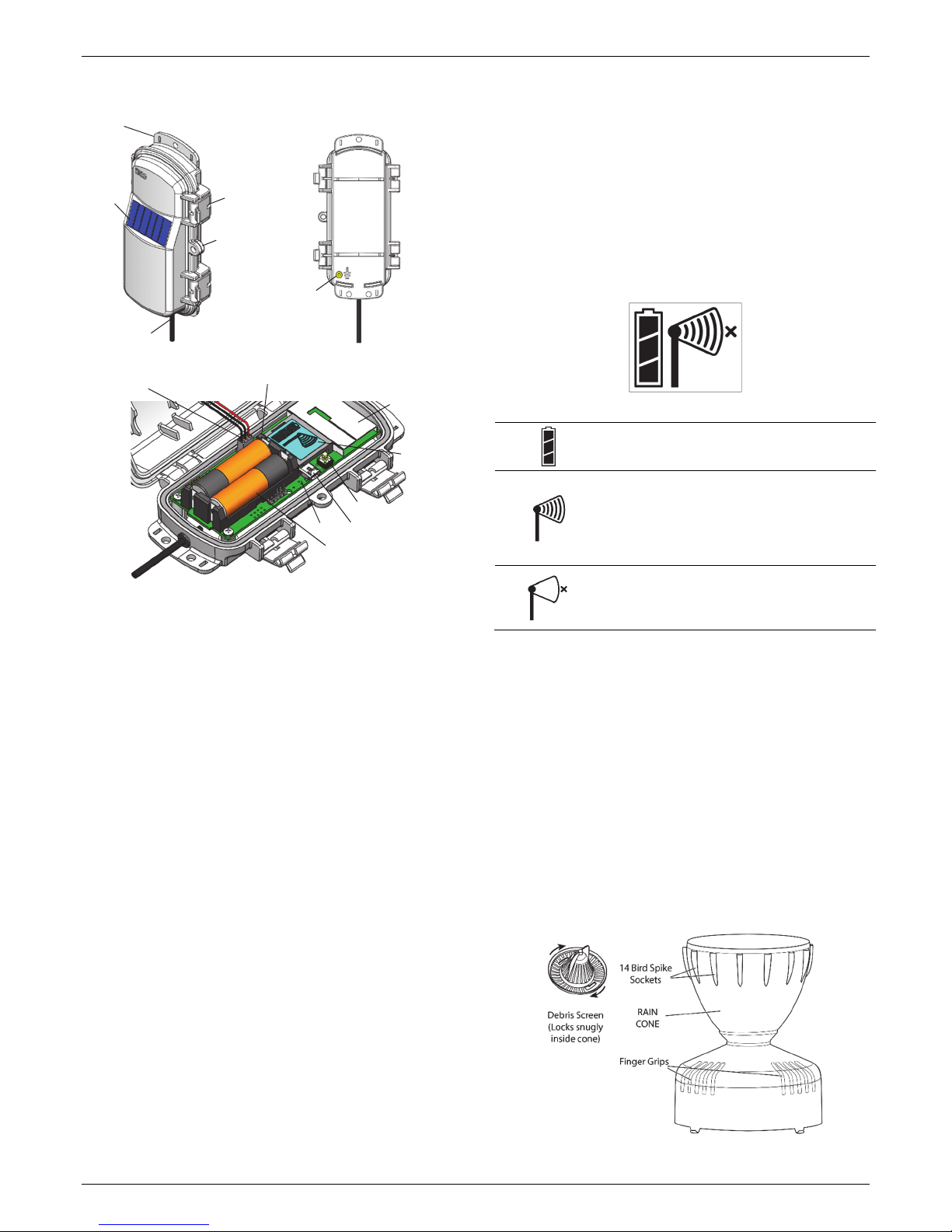
•Position the mote towards the sun, making sure the solar
panel is oriented so that it receives optimal sunlight
throughout each season. It may be necessary to
periodically adjust the mote position as the path of the
sunlight changes throughout the year or if tree and leaf
growth alters the amount of sunlight reaching the solar
panel.
•Make sure the mote door is closed, with both latches fully
locked to ensure a watertight seal.
•Consider using a 3/16 inch padlock to restrict access to the
mote. With the mote door closed, hook a padlock through
the eyelet on the right side of the door and lock it.
•To maximize the communication between motes, place
the mote within 304.8–457.2 m (1,000–1,500 feet) and full
line of sight with the next mote in the network and at least
1.8 m (6 feet) from the ground.
•If there is an obstruction between two sensor motes or
between the sensor mote and the RXW Manager, then use
an RXW Repeater (RXW-RPTR-xxx) mounted higher than
the two motes. For example, if there is a hill or mountain
between the sensor mote and the RXW Manager, place a
repeater at the top of the hill between the sensor mote
and the RXW Manager.
•There should not be more than five motes in any direction
from a repeater or the RXW Manager. Data logged by a
wireless sensor must travel or “hop” across the wireless
network from one mote to the next until it ultimately
reaches the RXW Manager at the RX3000 station. To make
sure the data can successfully travel across the network,
the sensor mote should not be more than five hops away
from a repeater or manager.
•The RX Wireless Sensor Network can support a maximum
of 50 motes.
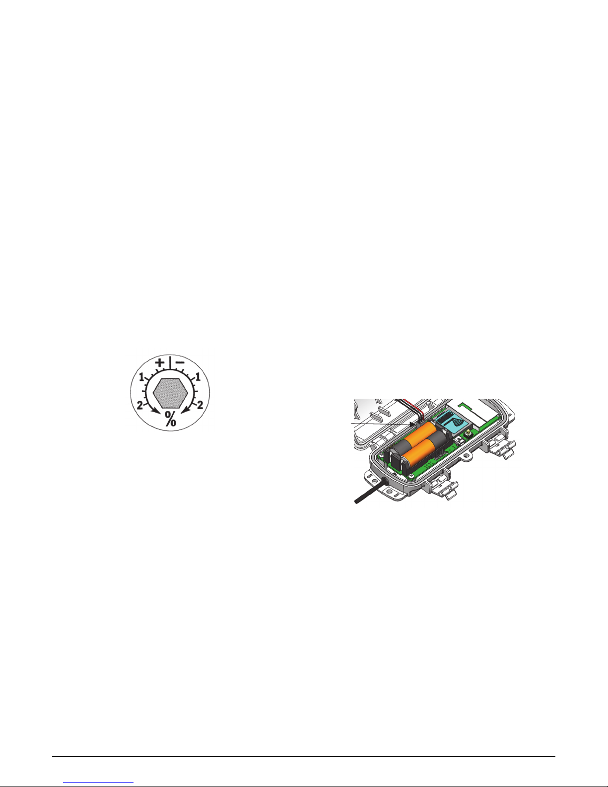
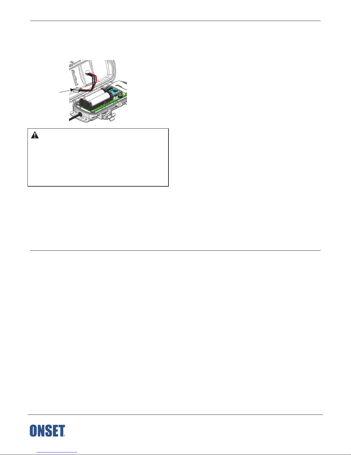
•Use a #4-40 screw to attach a ground wire to the port on
the back of the mote if you are deploying the mote in a
location where lightning is a concern.
•Make sure the mote remains in a vertical position once it
is placed in its deployment location for optimal network
communications.
Sensor Mounting Guidelines
Use the following guidelines to determine the best location for
installing the sensor.
•You must mount the rain gauge sensor so that it is level. As
built-in bubble level is attached to the base to simplify this
process.
•Be sure there is an unobstructed path for water runoff
from the drain screens.
•The sensor contains a magnet-operated switch that may
not operate correctly if you mount the rain gauge on or
near any object that is attracted to a magnet.
•Exposure to winds can reduce the measured rainfall
amounts. Mount the sensor where there are no
obstructions of rainfall at low angles (such as trees,
houses, fences) and as low as possible out of the wind.
•If installing the sensor on a sheet metal roof, insulate the
unit by making a platform out of wood. Mount the base of
the rain gauge at least 4 cm (1 inch) away from any steel
or iron surface and make sure the reed switch is at least 4
cm (1 inch) away from any steel or iron objects (e.g. nails).
•For the most accurate rainfall measurements, it is
recommended that you mount the sensor upslope, about
3 meters (10 feet) away from the tripod, on a 1.5 meter
high mounting pole (M-MPB). Alternatively, you can
mount the sensor on the tripod mast.
•Tall objects can interfere with accurate rain measurements.
It is recommended that you place the rain bucket away
from the obstruction by a distance greater than three times
the height of the obstruction. If that is not possible, raise
the rain bucket as high as possible to avoid shedding.
•Avoid splashing and puddles. Be sure the gauge is high
enough above any surface that rain will not splash into the
top of the collector.
•Vibration can significantly degrade accuracy of the tipping
bucket mechanism. In windy locations make sure that the
bucket will be vibration-free. Consider using guy wires to
secure a pole or tower-mounted bucket.
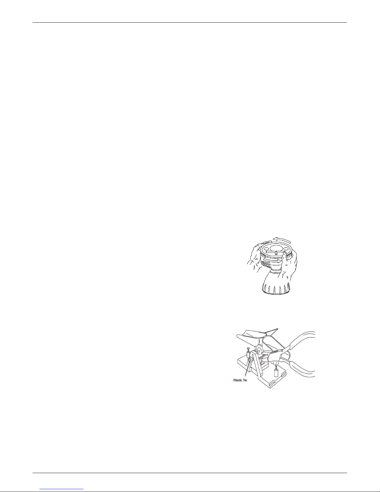
Preparing the Sensor for Mounting
1. Remove the cone from the base by turning over the bucket.
Rotate the base counterclockwise until the latches on the
cone line up with the latch openings in the base, then lift
the base off the cone.
2. The tipping bucket on the base has been secured to avoid
possible damage to the assembly. Carefully cut and remove
the cable tie to release the bucket assembly.
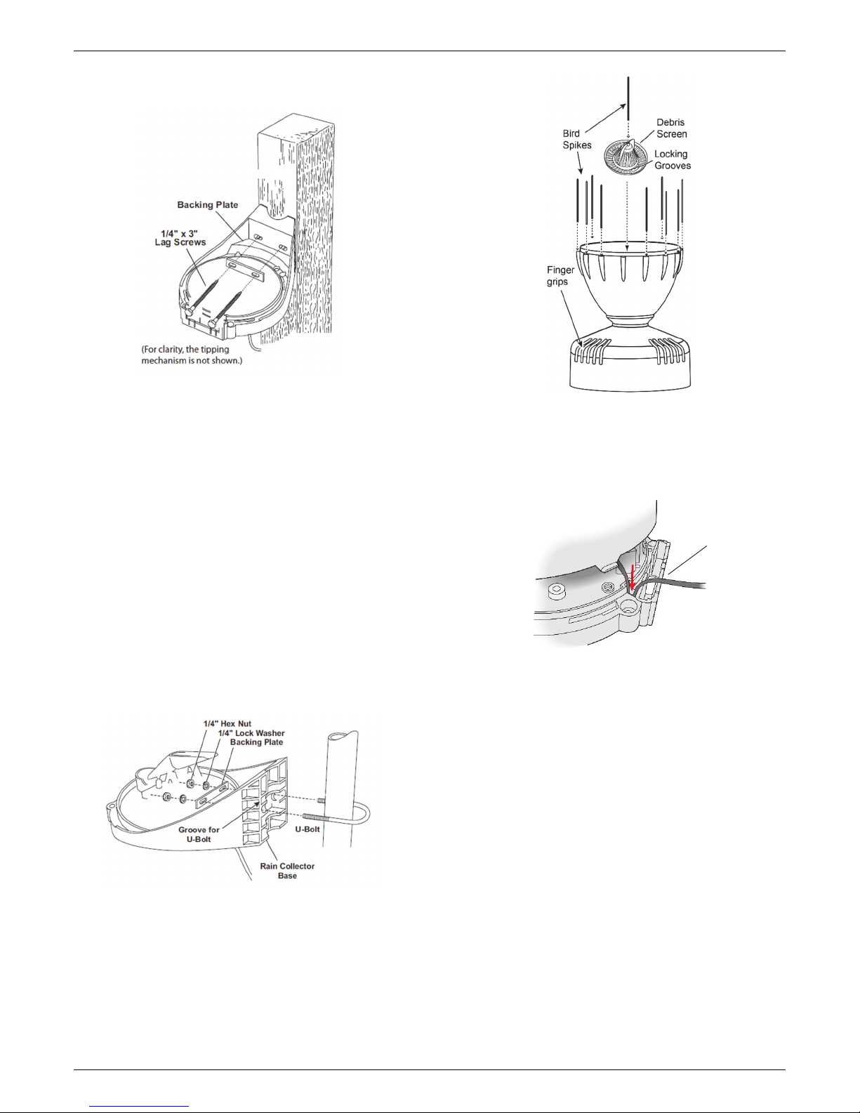
Mounting the Sensor on a Wooden Post or Flat Surface
1. With a 5 mm (3/16 inch) drill bit, drill two holes
approximately 54 mm (2-1/8 inches) apart. Use the metal
backing plate as a guide when marking the holes and a
carpenter’s level to ensure the holes are level.
2. Insert the 1/4 inch x 3 inch lag screws through the metal
backing plate and the holes in the mounting base into the
post. Make sure the base is level by checking the built-in
bubble level.

Rain Gauge Smart Sensor (S-RGC-M002 & S-RGD-M002) Manual
1-800-LOGGERS 5 www.onsetcomp.com
3. Tighten the lag screws using an adjustable wrench or 7/16
inch wrench.
Mounting the Sensor on a Pole or Mast
With the supplied U-bolt, the rain collector can be mounted on
a pole having an outside diameter ranging from 32 to 44 mm
(1-1/4 to 1-3/4 inch). A larger U-bolt (not supplied) can be used
to mount to a pole with a maximum outside diameter of 64 mm
(2-1/2 inch).
To mount on a smaller pole, obtain a U-bolt that fits the base
openings but has a shorter threaded section. If the included U-
bolt is used with a smaller pole, the bolt will interfere with the
rain collector cone.
Use the built-in bubble level to ensure the sensor is level.
1. While holding the mounting base against the pole, place the
two ends of a U-bolt around the pole and through the two
holes in the base.
2. Slide the metal backing plate over the bolt ends as they
stick out toward the rain collector cone. Secure the backing
plate with a washer, a lock washer, and a hex nut on each of
the bolt ends. Adjust the height of the rain collector, then
tighten the nuts.
Completing the Sensor Installation
1. To use bird spikes, insert one spike into each socket around
the rim of the cone. The sockets are tapered; push firmly or
tap lightly with a hammer for a more secure fit. Be careful;
bird spikes may be sharp. Note: If you choose not to install
the bird spikes, we recommend that you keep the packet of
spikes in case birds become a problem in the future.
2. Place the cone back onto the base by putting the latches on
the cone into the latch openings in the base and rotating
the cone clockwise until the latches “lock” into place. As
you reattach the cone, make sure to run the cable through
the cable slot in the base or the cone will not fit snugly
against the base.
3. Place the debris screen, pointed end up, into the cone. The
screen prevents large bits of debris from blocking the funnel
hole. If bird nesting is a problem, you can place a spike in
the hole on top of the debris screen. Note that using a bird
spike in the debris screen may make the screen more likely
to be blown over or out in a high wind gust.
4. To prevent fraying or cutting the cable where it is exposed
to weather, secure it so it does not whip about in the wind.
Use electrical tape or weather resistant cable ties to secure
the cable. Place tape or ties approximately every 1 to 1.6 m
(3 to 5 ft). Do not use metal staples to secure cables as they
can cut the cables. Make sure there are drip loops on both
sides of the sensor housing, which must also be mounted
horizontally as described under Sensor Mounting
Guidelines.
Maintenance
For greatest accuracy, you should thoroughly clean the sensor
at least once or twice a year.
1. Separate the cone from the base.
2. Use a soft damp cloth to clean pollen, dirt, and other debris
from the cone, cone screens, and bucket.
Place cable
in groove to
ensure the
cone is
properly
aligned with
the base

Rain Gauge Smart Sensor (S-RGC-M002 & S-RGD-M002) Manual
1-800-LOGGERS 6 www.onsetcomp.com
3. Use a pipe cleaner to clear the funnel hole in the cone and
the drain screens in the base. When all parts are clean, rinse
with clear water.
4. Reattach the cone and replace the screen.
The mote is designed for outdoor use, but should be inspected
periodically. When inspecting the mote, do the following:
•Verify the mote is free of visible damage or cracks.
•Make sure the mote is clean. Wipe off any dust or grime
with a damp cloth.
•Wipe off any water before opening the mote.
•Make sure the interior seal is intact and the latches are
fully locked when the mote door is closed.
Field Calibration
The sensor is calibrated at the factory so the spoons tip (and
record rainfall) for each 0.2 mm or 0.01 inch of rain. To adjust
the calibration slightly, use a 5 mm (3/16 inch) wrench to rotate
the adjustment screws located underneath the tipping spoons
(see diagram in Sensor Components and Operation). Do not
touch the reed switch.
The adjustment guide embossed in the platform shows how far
you must rotate both screws in turn to effect a 1% and a 2%
change.
Moving the screws in the positive (+) direction causes the
spoons to tip more times (i.e. give a larger count) for a given
amount of water. Modify both adjustment screws by the same
amount.
To check the accuracy of the sensor, compare it with a tube
type rain gauge. Use a rain gauge with an aperture of at least
10.2 cm (4 inches). Any smaller and the readings obtained may
not be accurate. Place the tube type rain gauge directly next to
the sensor. Compare the totals on three storms to determine
whether your rain collector needs calibration and by how
much. Adjust the screws to fine-tune the reading for the next
three storms if necessary.
Updating Mote Firmware
If a new firmware version is available for the mote, use
HOBOlink to download the file to your computer. Connect the
mote to the computer with a USB cable (open the mote door
and use the USB port to the right of the LCD). The mote appears
as a new storage device in the computer’s file storage manager.
Copy the downloaded firmware file to the new storage device
(the mote). After the file is copied, eject the storage device
from the computer and disconnect the cable from the mote.
The file will be installed automatically on the mote. Note to
Mac® users: A message may appear indicating the disk has not
ejected properly. The mote is operational and you can ignore
the message.
Battery Information
The mote uses two 1.2 V rechargeable NiMH batteries, charged
by the built-in solar panel. The quality and quantity of solar
light can affect whether the battery is sufficiently charged to
last through the night and cloudy periods. Make sure the mote
is placed in a location that will receive several hours of sunlight
each day. If the mote does not receive enough sunlight to
recharge the batteries, the battery life is estimated at 3–4
months. When batteries are regularly recharged, expected
battery life is estimated at 3–5 years. Battery life varies based
on the ambient temperature where the mote is deployed, the
logging interval, the number of tripped alarms, and other
factors. Deployments in extremely cold or hot temperatures
can impact battery life. Estimates are not guaranteed due to
uncertainties in initial battery conditions and operating
environment.
Mote operation will stop when battery voltage drops to 1.8 V.
Mote operation will return if the battery recharges to 2.3 V. If
the batteries are unable to be recharged, replace them with
fresh rechargeable batteries.
To replace rechargeable batteries:
1. Open the mote door.
2. Remove the old batteries and install the new ones
observing polarity.
3. Make sure the solar panel cable is plugged in.
You can use two 1.5 V lithium batteries (HWSB-LI) for operation
at the extreme ends of the mote operating range. Lithium
battery life is an estimated at 1 year, but varies based on the
ambient temperature where the mote is deployed, the logging
interval, the number of tripped alarms, and other factors.
Estimates are not guaranteed due to uncertainties in initial
battery conditions and operating environment. When using
lithium batteries, you must disconnect the solar panel cable
because the batteries will not be recharged.
To install lithium batteries:
1. Open the mote door.
2. Remove any old batteries and install the new ones
observing polarity.
3. Push in the side tab of the solar panel cable connector and
pull the connector out of the cable port.
Make sure
solar panel
cable is
installed
when using
rechargeable
batteries

RXW Davis 0.01" or 0.2 mm Rain Gauge Sensor (RXW-RGx-xxx) Manual
1-800-LOGGERS (564-4377) • 508-759-9500
www.onsetcomp.com/support/contact
© 2018 Onset Computer Corporation. All rights reserved. Onset, HOBO, and HOBOlink are registered
trademarks of Onset Computer Corporation. Some material reprinted with permission from Davis Instruments
Corporation. Davis is a registered trademark of Davis Instruments Corporation. Mac is a registered trademark
of Apple Inc. All other trademarks are the property of their respective companies.
22244-2
4. Place the connector in the slot on the inside of the mote
door. Make sure the solar panel cables are tucked inside the
door so that they do not interfere with the interior seal
when the mote is closed.
WARNING: Do not cut open, incinerate, heat above 85°C
(185°F), or recharge the batteries. The batteries may explode if
the logger is exposed to extreme heat or conditions that could
damage or destroy the battery cases. Do not mix battery types,
either by chemistry or age; batteries may rupture or explode.
Do not dispose of the logger or batteries in fire. Do not expose
the contents of the batteries to water. Dispose of the batteries
according to local regulations.
Federal Communication Commission Interference Statement
This equipment has been tested and found to comply with the limits for a Class B digital device, pursuant to Part 15 of the FCC Rules. These limits are designed to provide
reasonable protection against harmful interference in a residential installation. This equipment generates uses and can radiate radio frequency energy and, if not installed and
used in accordance with the instructions, may cause harmful interference to radio communications. However, there is no guarantee that interference will not occur in a
particular installation. If this equipment does cause harmful interference to radio or television reception, which can be determined by turning the equipment off and on, the user
is encouraged to try to correct the interference by one of the following measures:
•Reorient or relocate the receiving antenna
•Increase the separation between the equipment and receiver
•Connect the equipment into an outlet on a circuit different from that to which the receiver is connected
•Consult the dealer or an experienced radio/TV technician for help
This device complies with Part 15 of the FCC Rules. Operation is subject to the following two conditions: (1) This device may not cause harmful interference, and (2) this device
must accept any interference received, including interference that may cause undesired operation.
FCC Caution: Any changes or modifications not expressly approved by the party responsible for compliance could void the user's authority to operate this equipment.
Industry Canada Statements
This device complies with Industry Canada license-exempt RSS standard(s). Operation is subject to the following two conditions: (1) this device may not cause interference, and
(2) this device must accept any interference, including interference that may cause undesired operation of the device.
Avis de conformité pour l’Industrie Canada
Le présent appareil est conforme aux CNR d'Industrie Canada applicables aux appareils radio exempts de licence. L'exploitation est autorisée aux deux conditions suivantes : (1)
l'appareil ne doit pas produire de brouillage, et (2) l'appareil doit accepter tout brouillage radioélectrique subi, même si le brouillage est susceptible d'en compromettre le
fonctionnement.
To comply with FCC and Industry Canada RF radiation exposure limits for general population, the logger must be installed to provide a separation distance of at least 20cm from
all persons and must not be co-located or operating in conjunction with any other antenna or transmitter.
Store the solar
panel connector
here when using
lithium batteries
This manual suits for next models
9
Table of contents
Other Hobo Accessories manuals

Hobo
Hobo S-LIA-M003 User manual

Hobo
Hobo RXW-SPER Series User manual

Hobo
Hobo S-LIA-M003 User manual

Hobo
Hobo WELL-CAP-02 User manual

Hobo
Hobo RXW TEROS-12 User manual

Hobo
Hobo S-WCG-M003 User manual

Hobo
Hobo RXW-THC Series User manual

Hobo
Hobo S-RGx-M002 User manual

Hobo
Hobo RXW-UC Series User manual

Hobo
Hobo RXW-WCF Series User manual

Hobo
Hobo Davis S-RGE-M002 User manual

Hobo
Hobo RXW 10HS User manual

Hobo
Hobo RXW-THC-B Series User manual

Hobo
Hobo HOBOnet RXW-THC-B Series User manual

Hobo
Hobo RX3000 Series User manual

Hobo
Hobo S-LWA-M003 User manual

Hobo
Hobo RXW series User manual

Hobo
Hobo RXW-GP3 Series User manual

Hobo
Hobo S-LIA-M003 User manual