Hobo RXW-WCF Series User manual

HOBO® RX Wireless Sensor Network
RXW Davis® Wind Speed and Direction Sensor (RXW-WCF-xxx) Manual
22245-2
This sensor measures wind speed and direction and is designed to work with the HOBO RX
Wireless Sensor Network in which data is transmitted wirelessly from the sensor mote across
the network to the RX3000 station and then uploaded to HOBOlink® web-based software. With
HOBOlink, you can monitor sensor readings, view graphs, set up alarms, download data, and
more.
Specifications
Sensor Wind Speed/Gust Wind Direction
Measurement Range 0 to 76 m/sec (0 to 170 mph) 0 to 355 degrees
Accuracy ±1.1 m/sec (±2 mph) or ±5% of
reading, whichever is greater
±7 degrees
Resolution 0.5 m/sec (1.1 mph) 1 degrees (0 to 355 degrees)
Starting Threshold ≤1 m/sec (2.2 mph) 1 m/sec (2.2 mph)
Turning Radius 108 mm (4.25 in.) Approximately 135 mm (5.25 in.)
Measurement Definition Cup revolutions are accumulated
every three seconds for the
duration of the logging interval (see
Measurement Operation)
Wind speed: Average speed for the
entire logging interval
Gust speed: The highest three-
second wind recorded during the
logging interval
Unit vector averaging used; vector
components for each wind
measurement are calculated every
three seconds for duration of
logging interval (see Measurement
Operation)
W
ireless Mote
O
perating Temperature
Range
-25° to 60°C (-13° to 140°F) with rechargeable batteries
-40 to 70°C (-40 to 158°F) with lithium batteries
Radio Power 12.6 mW (+11 dBm) non-adjustable
Transmission Range At least 304.8 m (1,000 ft) line of sight at 1.8 m (6 ft) from the ground,
457.2 m (1,500 ft) typical
Wireless Data Standard IEEE 802.15.4
Radio Operating
Frequencies
RXW-WCF-900: 904–924 MHz
RXW-WCF-868: 866.5 MHz
RXW-WCF-922: 916–924 MHz
Modulation Employed OQPSK (Offset Quadrature Phase Shift Keying)
Data Rate Up to 250 kbps, non-adjustable
Duty Cycle <1%
Maximum Number of
Motes
50 motes per one RX Wireless Sensor Network
Battery Type/
Power Source
Two AA 1.2V rechargeable NiMH batteries, powered by built-in solar panel
or two AA 1.5 V lithium batteries for operating conditions of -40 to 70°C (-40
to 158°F)
Battery Life With NiMH batteries: Typical 3–5 years when operated in the temperature
range -20° to 40°C (-4°F to 104°F) and positioned toward the sun (see
Deployment and Mounting), operation outside this range will reduce the
battery service life
With lithium batteries: 1 year, typical use
Dimensions Sensor: 470 x 191 x 121 mm (18.5 x 7.5 x 4.75 in.)
Cable length: 3 m (9.8 ft)
Mote: 16.2 x 8.59 x 4.14 cm (6.38 x 3.38 x 1.63 inches)
Weight Sensor and cable: 1.332 kg (2 lb, 15 oz)
Mote: 223 g (7.87 oz)
RXW Davis Wind Speed &
Direction Sensor
Models:
•RXW-WCF-900 (US)
•RXW-WCF-868 (Europe)
•RXW-WCF-922
(Australia/NZ)
Items Included:
•Cable ties
Items required:
•Weather-resistant cable
ties or cable clips
•Electrical tape
•Handheld compass, local
area map, or handheld GPS
If mounting on tripod or mast:
•Adjustable wrench
If mounting on wooden surface:
•Drill with 5 mm (3/16 inch)
drill bit
Accessories:
•Grounding kit (M-GKA)

RXW Davis Wind Speed and Direction Sensor (RXW-WCF-xxx) Manual
1-800-LOGGERS 2 www.onsetcomp.com
Specifications (continued)
Materials Sensor: Polycarbonate wind cups, sealed stainless steel bearing, UV-resistant
ABS wind vane and black-anodized aluminum anemometer arm
Mote: PCPBT, silicone rubber seal
Environmental Rating Sensor: Weatherproof
Mote: IP67
C
ompliance Marks RXW-WCF-900: See last page
RXW-WCF-868: The CE Marking identifies this product as
complying with all relevant directives in the European Union (EU).
RXW-WCF-922: See last page
Mote Components and Operation
Sensor Mote Closed, Front Sensor Mote Closed, Back
Sensor Mote Opened
Mounting Tab: Use the tabs at the top and bottom of the mote
to mount it (see Deploying and Mounting).
Solar Panel: Position the solar panel towards the sun to charge
the mote batteries (see Deploying and Mounting).
Sensor Cable: This is the cable that connects the mote to the
sensor.
Eyelet: Use this eyelet to attach a 3/16 inch padlock to the
mote for security.
Latch: Use the two latches to open and close the mote door.
Ground Wire Port: Use this port to connect a ground wire (see
Deploying and Mounting).
Antenna: This is the built-in antenna for the radio
communications across the RX Wireless Sensor Network.
Solar Panel Cable: This cable connects the built-in solar panel
to the mote circuitry.
LEDs: The blue LED to the left of the LCD screen blinks at 4
seconds during normal operation. It blinks more frequently
when initially joining a network. If the mote is not currently
part of a network, the blue LED will be off. If the LED is on and
not blinking, there is a problem with the mote. Contact
Technical Support at www.onsetcomp.com/support/contact.
The yellow-green LED to the upper right of the batteries only
blinks during the process of joining a network.
Battery Holder: The location where the rechargeable AA
batteries are installed as shown (see Battery Information).
USB Port: Use this port to connect to the mote to a computer
via USB cable if you need to update the firmware (see Updating
Mote Firmware).
Button: Push this button for 1 second to illuminate the LCD or 3
seconds for the mote to search for an RX Wireless Sensor
Network to join (see Adding the Mote to the RX Wireless Sensor
Network).
LCD Screen: The mote is equipped with an LCD screen that
displays details about the current status. This example shows all
symbols illuminated on the LCD screen followed by definitions
of each symbol in the table.
LCD Symbol Description
The battery indicator shows the approximate
battery charge remaining.
This is a signal strength indicator. The more bars,
the stronger the signal between motes. This icon
will blink when you press the button on the mote
to search for a network to join (see Adding the
Mote to the RX Wireless Sensor Network for
details).
This indicates that the mote is not part of a
network. See Adding the Mote to the RX Wireless
Sensor Network for details on how to add a mote
to the network.
Solar Panel
Button
USB Port
Battery Holder
LCD Screen
Latch
LED
Eyelet
Ground Wire
Port
Mounting
Tab
Sensor Cable
Solar Panel Cable
Antenna
LED

RXW Davis Wind Speed and Direction Sensor (RXW-WCF-xxx) Manual
1-800-LOGGERS 3 www.onsetcomp.com
Sensor Components
The sensor includes the components shown below.
The sensor also includes a hardware kit with the items most
commonly needed for installation as shown below. The items
you use from the kit depend on where you install the sensor.
You may need to adapt or purchase additional hardware to fit
your individual requirements.
Adding the Mote to the RX Wireless Sensor
Network
The mote must join an RX Wireless Sensor Network before it
can begin measuring wind speed and direction and transmitting
data. This requires accessing the RX3000 Station and the mote
at the same time so it is recommended that you complete
these steps before deploying the mote.
Important: If you have not configured the RX3000 Station with
the RXW Manager, follow the instructions in the RX3000 Quick
Start before continuing.
To add a mote to the RX Wireless Sensor Network:
1. If the LCD is blank on the RX3000 station, press any button
to wake it up.
2. Press the Select button once (which shows the number of
smart sensors installed) and then press it again once if the
HOBO RXW Manager is installed in the left slot (module 1)
or twice if it is installed on the right slot (module 2).
3. Press the Search button (the magnifying glass). The
magnifying glass icon will blink while the RX3000 is in search
mode.
4. Open the mote door and install the batteries if you have not
already done so.
5. Press the button on the mote for 3 seconds. The signal
strength icon will flash and then cycle.
6. Watch the LCD on the mote. The signal strength icon and
the LEDs will quickly blink while the mote searches for the
wireless network. Once it has found the network, the icon
will stop blinking and the signal strength bars will slowly
cycle from left to right. As the mote completes its
registration process with the network, the “x” icon to the
right of the signal strength icon will flash and the yellow-
green LED will stop blinking. Once the registration is
complete, the signal strength bars will stop cycling and
remain solid and the channel count on the RX3000 LCD will
be updated. This process may take up to five minutes. Note:
The channel count on the LCD will increase by 3: two for
wind speed and direction, and one for the mote battery.
Press this button to view the module
where the RXW Manager is installed
Press this button so the station is ready
to have motes join the network
Press this button for 3
seconds for the mote to
join the network

RXW Davis Wind Speed and Direction Sensor (RXW-WCF-xxx) Manual
1-800-LOGGERS 4 www.onsetcomp.com
7. Press the Search button (the magnifying glass) on the
RX3000 Station to stop searching for motes.
Measurements will be recorded at the logging interval specified
in HOBOlink, transmitted to the RX3000 Station, and uploaded
to HOBOlink at the next connection interval (readout). Use
HOBOlink to monitor mote status and health. If a mote is
temporarily offline, any logged data is saved until it is back
online. In addition, if a mote is offline for 30 minutes, the
RX3000 Station will automatically connect to HOBOlink and
report the mote as missing. Once the mote is back online, any
logged data will be uploaded the next time the RX3000 station
connects to HOBOlink.
See the HOBOlink Help for details on how to change the logging
and connection intervals, view data, check mote status, add the
mote to a map, and more.
Assembling the Sensor
Attaching the Wind Vane
The wind direction has been calibrated in the factory so that
the wind direction will be correct when the arm is installed
pointing north and the vane is installed correctly.
1. Slide the wind vane onto the wind vane shaft. The shaft’s
cross-section is D-shaped to ensure that the anemometer is
installed correctly.
2. Tighten the set screw in the wind vane with the Allen
wrench.
Attaching the Wind Cups
1. Push the wind cups onto the anemometer’s stainless steel
wind cup shaft.
2. Slide the wind cups up the shaft as far as possible.
3. Use the Allen wrench provided to tighten the set screw on
the side of the wind cups. The wind cups should drop
slightly when you let go.
4. Ensure the set screw is screwed in fully and very tight.
Failure to do so will cause the anemometer to function
improperly.
5. Spin the wind cups; they should spin freely. If they do not
spin freely, take them off and repeat these steps
Attaching the Anemometer Arm to the Base
1. Insert the anemometer arm into the base, sliding the cable
through the notch in the base as shown below. Be sure to
line up the small hole in the arm with the holes in the base.
2. Insert the machine screw through the holes in the base and
arm.
3. Slide the tooth-lock washer and hex nut onto the machine
screw. Tighten the hex nut while holding the screw with a
Phillips head screwdriver to prevent it from turning.
4. Press the sensor cable firmly and completely into the zig-
zagging channel in the base, starting from the arm and
progressing downward to the bottom of the base.
Deployment and Mounting
Mounting and Positioning the Mote
•Use cable ties to mount the mote via the holes on the
mounting tabs.
•Avoid mounting the mote near metal, which can cause
interference with the signal.
•Position the mote towards the sun, making sure the solar
panel is oriented so that it receives optimal sunlight
throughout each season. I It may be necessary to
periodically adjust the mote position as the path of the
sunlight changes throughout the year or if tree and leaf
growth alters the amount of sunlight reaching the solar
panel.
•Make sure the mote door is closed, with both latches fully
locked to ensure a watertight seal.
Press this button again to
stop searching for motes

RXW Davis Wind Speed and Direction Sensor (RXW-WCF-xxx) Manual
1-800-LOGGERS 5 www.onsetcomp.com
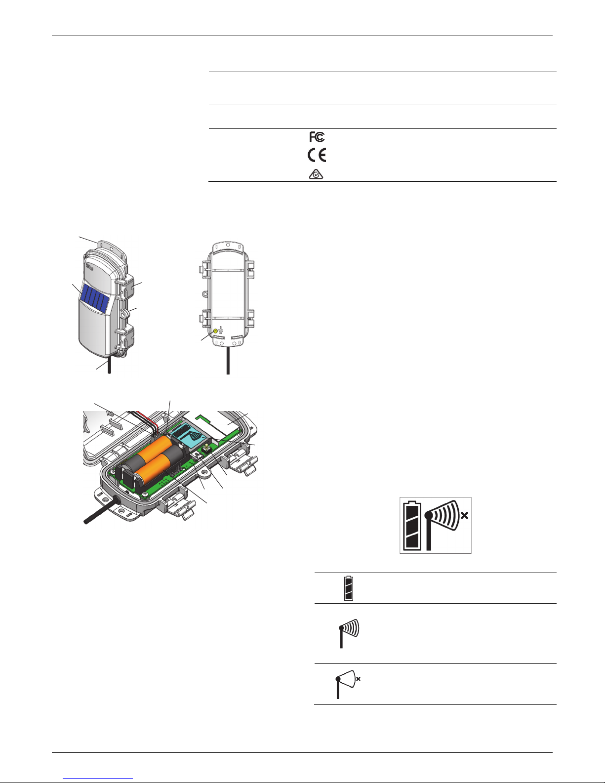
•Consider using a 3/16 inch padlock to restrict access to the
mote. With the mote door closed, hook a padlock through
the eyelet on the right side of the door and lock it.
•To maximize the communication between motes, place
the mote within 304.8–457.2 m (1,000–1,500 feet) and full
line of sight with the next mote in the network and at least
1.8 m (6 feet) from the ground.
•If there is an obstruction between two sensor motes or
between the sensor mote and the RXW Manager, then use
an RXW Repeater (RXW-RPTR-xxx) mounted higher than
the two motes. For example, if there is a hill or mountain
between the sensor mote and the RXW Manager, place a
repeater at the top of the hill between the sensor mote
and the RXW Manager.
•There should not be more than five motes in any direction
from a repeater or the RXW Manager. Data logged by a
wireless sensor must travel or “hop” across the wireless
network from one mote to the next until it ultimately
reaches the RXW Manager at the RX3000 station. To make
sure the data can successfully travel across the network,
the sensor mote should not be more than five hops away
from a repeater or manager.
•The RX Wireless Sensor Network can support a maximum
of 50 motes.
•Use a #4-40 screw to attach a ground wire to the port on
the back of the mote if you are deploying the mote in a
location where lightning is a concern.
•Make sure the mote remains in a vertical position once it
is placed in its deployment location for optimal network
communications.
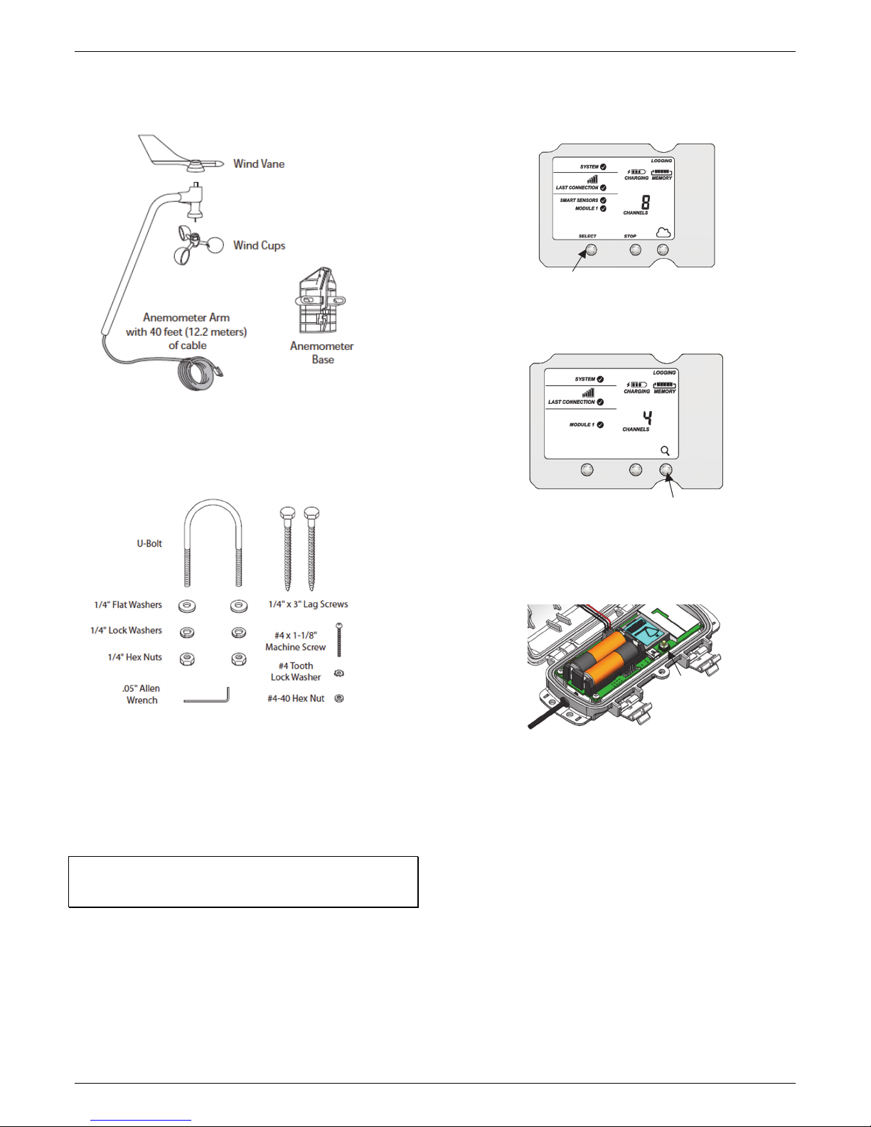
Sensor Mounting Guidelines
Use the following guidelines to determine the best location for
installing the sensor.
•To ensure correct orientation of the wind vane, the sensor
must be mounted so that the anemometer arm points
north. See North Alignment for steps on finding true north.
•For the most accurate readings, the sensor should be
mounted 2 m (7 ft) or more above the ground and
consistent with meteorological standards for the
application. The sensor should be mounted at least 2.1 m
(7 ft) above the roof line if mounted on a roof and
mounted at a distance of at least five times the height of
the nearest tree, building, or other obstruction. You may
do this by mounting the sensor on an Onset tripod or
mast, or a metal pipe. You may mount the sensor on a
wooden post if it has a side facing due north for mounting.
•The tripod or mounting mast must be properly grounded.
For field installations, you can use Onset’s Grounding Kit
(M-GKA).
•If you live in an area subject to frequent thunderstorms,
installing a lightning rod nearby can reduce the risk of
damage.
•Be sure to secure the sensor cable with cable ties to
protect it from damage.
•Secure the mast the wind sensor is mounted on so that it
does not vibrate. If you are using Onset masts or tripods,
secure them with guy wires.
•The sensor can be damaged with improper handling. Store
the sensor in its shipping box until you are ready to install it.
•To minimize measurement errors due to ambient RF, use
the shortest possible probe cable length and keep the
probe cable as far as possible from other cables carrying
high frequency or high current signals.
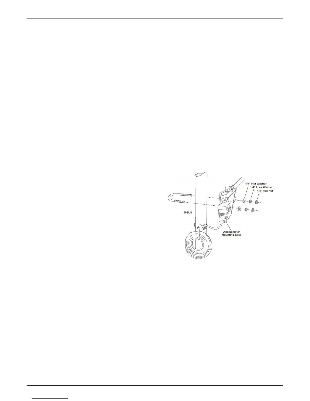
Sensor Mounting on a Mast
Follow these instructions for mounting the sensor on a tripod
or mast. The U-bolts included can be used for mounting the
sensor on a mast or tripod with an outside diameter ranging
from 32–44 mm (1.25–1.75 inches). Larger U-bolts (not
supplied) can be used to mount on a mast or tripod with a
maximum outside diameter of 64 mm (2.5 inches). To mount
the sensor on a mast or tripod smaller than 32 mm (1.25
inches), use a U-Bolt that fits the anemometer base openings,
but has a shorter threaded section.
1. Place the U-bolt around the pole so that its two ends
extend through the holes in the mounting base. Loosely
secure with the flat washers, lock washers, and hex nuts.
2. Raise the anemometer to the desired height on the pole
and swivel it so the anemometer arm is pointing north.
3. Using an adjustable wrench or 7/16 inch wrench, tighten
the hex nuts until the anemometer is firmly fastened on the
pole.
Sensor Mounting on a Wooden Post or Surface
Follow these instructions for mounting the sensor on a wooden
post or surface. The sensor must be mounted on the side that is
facing due north (the mounting arm must point north for
proper wind direction measurements).
1. Hold the anemometer base against the wood surface and
use a pencil to mark the location of the two holes on the
base.
2. Use a drill with a 5 mm (3/16 inch) drill bit to make pilot
holes in these locations.

RXW Davis Wind Speed and Direction Sensor (RXW-WCF-xxx) Manual
1-800-LOGGERS 6 www.onsetcomp.com
3. Drive the 3-inch lag screws through the holes in the
anemometer base and into the wood.
Securing the Sensor Cables
To prevent fraying or cutting the anemometer cables where it is
exposed to weather, secure it so it does not whip about in the
wind. Use cable clips or weather resistant cable ties to secure
the cable. Place clips or cable ties approximately every 1 to 1.6
m (3 to 5 ft). Do not use metal staples to secure cables as they
can cut the cables.
Measurement Operation
Wind speed measurements are averaged automatically every 3
seconds within each logging interval. Wind speed is reported as
the average speed for the entire logging interval. For example,
if the logging interval is set to 1 minute, then 20 measurements
(1 measurement every 3 seconds for 60 seconds) are averaged
together and the result is logged each minute. The gust speed is
the highest 3-second wind recorded during the logging interval.
Unit vector averaging is used to determine wind direction
because traditional averaging would produce inaccurate
results. For example, three measurements of 350, 11, and 12
degrees—which are all winds from the north—averaged
together would result in 126 degrees, which incorrectly
indicates a southeasterly wind. Instead, the vector components
(North/South and East/West) for each wind measurement are
calculated every three seconds for the duration of the logging
interval. At the conclusion of the logging interval, the
North/South and East/West components are averaged and
then re-combined to calculate the average wind direction for
the logging interval.
North Alignment
The sensor must be oriented to true north to obtain meaningful
data. There are two methods to align the sensor:
•Compass Alignment
•Global Positioning Satellite (GPS) alignment
Note: The magnetic declination must be known to align the
direction sensor to true north using a magnetic compass.
Worldwide declination information is available from the
National Space Science Data Center at:
http://nssdc.gsfc.nasa.gov/space/cgm/cgm.html.
Compass Alignment
Tools required:
•Compass
•Binoculars
•Tape (such as electrical, packing, or duct tape)
Two people are required to complete this procedure.
1. Position the wind vane so that it points in the same
direction as the mounting arm. Secure the vane on the arm
with a piece of tape so that the vane cannot rotate.
2. While standing 150 to 200 feet south of the sensor, use the
compass to determine magnetic north. If true north is the
same as magnetic north, align yourself so the compass
points north and directly at the sensor. If you are in area
with an east variation, align yourself so that the station is
that number of degrees to the east of magnetic north. If
you are in an area with a west variation, align yourself so
that the station is that number of degrees to the west of
magnetic north.
3. While viewing the sensor through binoculars, instruct
another person to rotate the arm to point the vane north.
The vane should seem to disappear from sight when
properly aligned.
4. Once you’ve obtained the correct position, secure the
sensor base and remove the tape.
GPS Alignment
Tools required:
•Handheld GPS with WAAS-enabled receiver or any
similar high accuracy GPS device
•Flag, orange cone, or other temporary marker
•Access to your HOBOlink account
This procedure requires only one person, but is easier to
complete with two people. In this procedure, you will be using
the GPS receiver first to create an arbitrary waypoint and then
to determine the bearing from the sensor to that waypoint. You
will then align the sensor so that when the vane is pointed at
the waypoint, the direction reported by HOBOlink matches the
GPS receiver’s bearing to the waypoint.
1. In HOBOlink, temporarily set the logging interval to 1 minute
or the fastest logging interval supported by the device
communication plan (if applicable). Refer to the online help
for details on operating HOBOlink.
2. Pick a visible location that is at least 100 meters (110 yards)
away from the sensor and walk to it. Establish a waypoint
with the handheld GPS receiver. You may want to use
averaging to minimize the waypoint position error if your
GPS receiver is so equipped. (For best results, the estimated
position error of the waypoint should be less than 10 feet if
the distance to the sensor is 100 meters, and less than 20
feet for a distance of 200 meters. Mark the waypoint with a
flag, orange cone, or other suitable marker. Walk back to
the sensor and determine the bearing to the waypoint you
just created with the GPS receiver. Again you may need to
determine the average value of the bearing to keep the
errors to a minimum.

RXW Davis Wind Speed and Direction Sensor (RXW-WCF-xxx) Manual
1-800-LOGGERS 7 www.onsetcomp.com
3. Check the latest reading in HOBOlink keeping in mind that
the data is only updated when the station connects to
HOBOlink. It may take a couple of connections before the
latest reading from the mote is transmitted to the station
and then uploaded to HOBOlink. The value should match
the angle obtained with the GPS receiver. If it does not,
reposition the sensor vane so that it is pointed directly at
the waypoint flag or marker and then rotate the sensor
mounting arm as needed and wait for the next HOBOlink
reading. Repeat this until the wind direction sensor value in
HOBOlink matches the angle obtained with the GPS
receiver.
4. Once the vane is in position, secure the mounting base and
then double-check that the reported angle is correct.
Maintenance
The sensor does not normally require any maintenance other
than an occasional cleaning. If the vane becomes dirty, rinse it
with mild soap and fresh water. Do not immerse the sensor in
water or use any organic solvents to clean the unit. Do not
attempt to lubricate the wind cup shaft or bearings or the wind
vane shaft. Natural or synthetic lubricants will inhibit the
normal operation of the anemometer.
The mote is designed for outdoor use, but should be inspected
periodically. When inspecting the mote, do the following:
•Verify the mote is free of visible damage or cracks.
•Make sure the mote is clean. Wipe off any dust or grime
with a damp cloth.
•Wipe off any water before opening the mote.
•Make sure the interior seal is intact and the latches are
fully locked when the mote door is closed.
Verifying Sensor Accuracy
It is recommended that you check the accuracy of the sensor
annually. The sensor cannot be calibrated. If the sensor is not
providing accurate data, then it is damaged or possibly worn
out if it has been in use for several years.
Updating Mote Firmware
If a new firmware version is available for the mote, use
HOBOlink to download the file to your computer. Connect the
mote to the computer with a USB cable (open the mote door
and use the USB port to the right of the LCD). The mote appears
as a new storage device in the computer’s file storage manager.
Copy the downloaded firmware file to the new storage device
(the mote). After the file is copied, eject the storage device
from the computer and disconnect the cable from the mote.
The file will be installed automatically on the mote. Note to
Mac® users: A message may appear indicating the disk has not
ejected properly. The mote is operational and you can ignore
the message.
Battery Information
The mote uses two 1.2 V rechargeable NiMH batteries, charged
by the built-in solar panel. The quality and quantity of solar
light can affect whether the battery is sufficiently charged to
last through the night and cloudy periods. Make sure the mote
is placed in a location that will receive several hours of sunlight
each day. If the mote does not receive enough sunlight to
recharge the batteries, the battery life is estimated at 3–4
months. When batteries are regularly recharged, expected
battery life is estimated at 3–5 years. Battery life varies based
on the ambient temperature where the mote is deployed, the
logging interval, the number of tripped alarms, and other
factors. Deployments in extremely cold or hot temperatures
can impact battery life. Estimates are not guaranteed due to
uncertainties in initial battery conditions and operating
environment.
Mote operation will stop when battery voltage drops to 1.8 V.
Mote operation will return if the battery recharges to 2.3 V. If
the batteries are unable to be recharged, replace them with
fresh rechargeable batteries.
To replace rechargeable batteries:
1. Open the mote door.
2. Remove the old batteries and install the new ones
observing polarity.
3. Make sure the solar panel cable is plugged in.
You can use two 1.5 V lithium batteries (HWSB-LI) for operation
at the extreme ends of the mote operating range. Lithium
battery life is an estimated at 1 year, but varies based on the
ambient temperature where the mote is deployed, the logging
interval, the number of tripped alarms, and other factors.
Estimates are not guaranteed due to uncertainties in initial
battery conditions and operating environment. When using
lithium batteries, you must disconnect the solar panel cable
because the batteries will not be recharged.
To install lithium batteries:
1. Open the mote door.
2. Remove any old batteries and install the new ones
observing polarity.
3. Push in the side tab of the solar panel cable connector and
pull the connector out of the cable port.
Make sure
solar panel
cable is
installed
when using
rechargeable
batteries

RXW Davis Wind Speed and Direction Sensor (RXW-WCF-xxx) Manual
1-800-LOGGERS (564-4377) • 508-759-9500
www.onsetcomp.com/support/contact
© 2018 Onset Computer Corporation. All rights reserved. Onset, HOBO, and HOBOlink are registered
trademarks of Onset Computer Corporation. Some material reprinted with permission from Davis Instruments
Corporation. Davis is a registered trademark of Davis Instruments Corporation. Mac is a registered trademark
of Apple Inc. All other trademarks are the property of their respective companies.
22245-2
4. Place the connector in the slot on the inside of the mote
door. Make sure the solar panel cables are tucked inside the
door so that they do not interfere with the interior seal
when the mote is closed.
WARNING: Do not cut open, incinerate, heat above 85°C
(185°F), or recharge the batteries. The batteries may explode if
the logger is exposed to extreme heat or conditions that could
damage or destroy the battery cases. Do not mix battery types,
either by chemistry or age; batteries may rupture or explode.
Do not dispose of the logger or batteries in fire. Do not expose
the contents of the batteries to water. Dispose of the batteries
according to local regulations.
Federal Communication Commission Interference Statement
This equipment has been tested and found to comply with the limits for a Class B digital device, pursuant to Part 15 of the FCC Rules. These limits are designed to provide
reasonable protection against harmful interference in a residential installation. This equipment generates uses and can radiate radio frequency energy and, if not installed and
used in accordance with the instructions, may cause harmful interference to radio communications. However, there is no guarantee that interference will not occur in a
particular installation. If this equipment does cause harmful interference to radio or television reception, which can be determined by turning the equipment off and on, the user
is encouraged to try to correct the interference by one of the following measures:
•Reorient or relocate the receiving antenna
•Increase the separation between the equipment and receiver
•Connect the equipment into an outlet on a circuit different from that to which the receiver is connected
•Consult the dealer or an experienced radio/TV technician for help
This device complies with Part 15 of the FCC Rules. Operation is subject to the following two conditions: (1) This device may not cause harmful interference, and (2) this device
must accept any interference received, including interference that may cause undesired operation.
FCC Caution: Any changes or modifications not expressly approved by the party responsible for compliance could void the user's authority to operate this equipment.
Industry Canada Statements
This device complies with Industry Canada license-exempt RSS standard(s). Operation is subject to the following two conditions: (1) this device may not cause interference, and
(2) this device must accept any interference, including interference that may cause undesired operation of the device.
Avis de conformité pour l’Industrie Canada
Le présent appareil est conforme aux CNR d'Industrie Canada applicables aux appareils radio exempts de licence. L'exploitation est autorisée aux deux conditions suivantes : (1)
l'appareil ne doit pas produire de brouillage, et (2) l'appareil doit accepter tout brouillage radioélectrique subi, même si le brouillage est susceptible d'en compromettre le
fonctionnement.
To comply with FCC and Industry Canada RF radiation exposure limits for general population, the logger must be installed to provide a separation distance of at least 20cm from
all persons and must not be co-located or operating in conjunction with any other antenna or transmitter.
Store the solar
panel connector
here when using
lithium batteries
This manual suits for next models
3
Table of contents
Other Hobo Accessories manuals

Hobo
Hobo RXW-THC Series User manual

Hobo
Hobo RXW 10HS User manual

Hobo
Hobo RXW-GP3 Series User manual

Hobo
Hobo RXW TEROS-12 User manual

Hobo
Hobo Davis S-RGE-M002 User manual

Hobo
Hobo RXW-UC Series User manual

Hobo
Hobo HOBOnet RXW-THC-B Series User manual

Hobo
Hobo S-LIA-M003 User manual

Hobo
Hobo S-RGx-M002 User manual

Hobo
Hobo RXW-SPER Series User manual