Hofmann Megaplan megaline SSENCE Series User manual

Hofmann Megaplan GmbH
3D Wheel Aligner
megaline SSENCE
megaline SSENCEmegaline SSENCE
megaline SSENCE
Service manual
Due to intellectual property rights. some features are not available in some countries.
Some items shown in this manual are options.
Hofmann Megaplan GmbH
Hauptstraße 67
5302 Henndorf am Wallersee
Austria
Tel: +43 6214 - 64 66 12 • Fax: +43 6214 - 64 66 22
HM-mail@hofmann-megaplan.com • www. hofmann-megaplan.com
25.02.2015

Hofmann M
egaplan Service Manual megaline SSENCE
SSENCE 400/600 Page 1 of 52
1.0 Maintenance
1.1 Regular maintenance of Aligner 4
1.2 Regular maintenance of computer 4
1.3 Maintenance of screen, system cameras and targets 4
1.4 Site selection 4
2.0 Repair of the aligner
2.1 Targets
2.1.1 Exchange of targets - mechanical part (all models) 5
2.1.2 Exchange of targets - electronically data (all models) 6
2.1.3 Loose of target files 6
2.2 Camera bar
2.2.1 Components of power supply for camera and motor 7
2.2.2 Exchange of motor controller (400M and 600) 8
2.2.3 Adjustment of motor controller (400M and 600) 9
2.2 4 Exchange of the steel rope of the camera bar (400 u. 600) 10
2.2.5 Camera bar runs over limiter switch 11
2.2.6 Exchange of limiter switch 12
2.2.7 Failure / wrong signals of the LED ring 12
2.3 Exchange of camera and camera chips
2.3.1 Check before changing the camera module 14
2.3.2 Change camera module 14
2.3.3 Possible failure of camera module 15
2.3.4 Possible failure of camera chips 16
2.3.5 Adjustment of camera chip by software 16
2.4 Different camera modules and LED IR panel
2.4.1 Different versions 18
2.4.1 Test and exchange IR-LEDs 18

Hofmann M
egaplan Service Manual megaline SSENCE
SSENCE 400/600 Page 2 of 52
3.0 Possible problems and failures
3.1 Increase of accuracy 19
3.2 Flare and reflections 19
3.3 Light influence from outside 20
3.4 Jumping values 20
3.5 USB interfaces for camera 21
3.6 Bad reflections of the targets (Car icon) 21
3.7 Prepare CAMBER corrections 22
3.8 Correction of CAMBER values in the configuration file 22
3.9 Machine is very slow and freezes in some positions. 23
3.10 Earth of the machine. 24
4.0 Handling of machines and software
4.1 Activation code required. 25
4.1.1 Activation code not accepted after system restart 26
4.2 Data base handling and Hardware lock (Dongle) 27
4.3 Calibration data 29
4.4 Backup of collected alignments, customized cars and user data 29
4.5 Garage data 30
4.6 Faulty power supply of the USB-ports 30
4.7 Printer installation 31
4.8 Resolution of the screen 31
4.9 Hardware of aligner in Device Manager 31
4.10 Camera picture is grey, blurring or complete white (F11) 31
4.11 ERROR USB CONNECTION while starting 32
4.12 Numbers close to the car icon in the bottom of the screen 32
4.23 Camera View [F11] 33
4.14 Values for exposure of the camera 33
5.0 Error Messages
5.1 Error messages 35
5.2 Internet connection 35

Hofmann M
egaplan Service Manual megaline SSENCE
SSENCE 400/600 Page 3 of 52
6.0 Miscellaneous
6.1 Information for service technicians 39
6.2 Explanation of serial number 39
6.3 Software updates 40
6.4 Team Viewer Support (Remote session) 41
6.5 Clamps - Size and technical drawing 42
6.6 Switch from Automatic to Manual (Camera bar) 43
6.7 Install shielded USB cables. 44
6.8 Install ANDROID remote control 46
6.9 Exchange of personal computer 49
Autodata Copyrights 51
Windows®,Android®, AutoData® and SSENCE® are registered trademarks-
©
©©
©Hofmann Megaplan GmbH 2014 HP

Hofmann M
egaplan Service Manual megaline SSENCE
SSENCE 400/600 Page 4 of 52
1.0 Maintenance
1.1 Regular maintenance of Aligner
Like every precise machine the aligner should have a continuous maintenance.
For this reason at least once a year a service is recommended.
The following tasks must be performed:
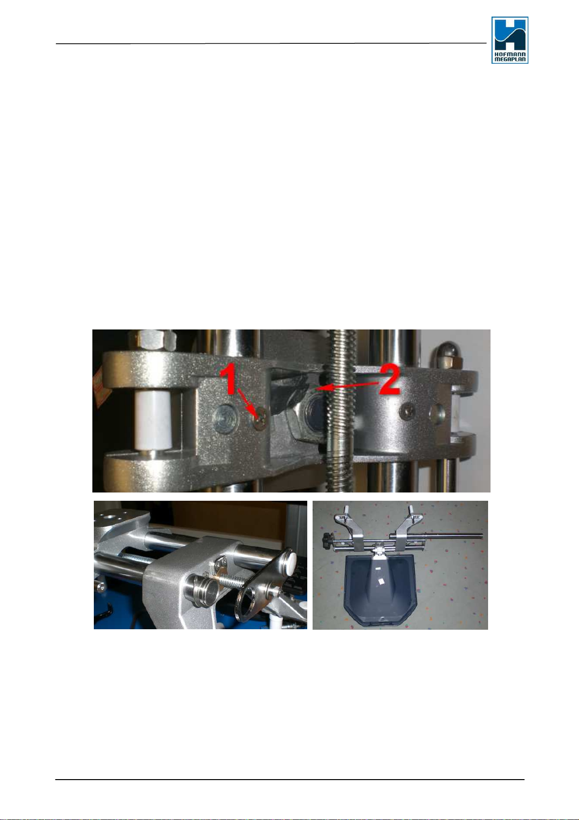
- Check the rope on the horizontal bar for damage and tight fit
- Check the pulleys (fixing, wear, lubrication)
- Check treads of the camera bar, add some silicone grease if necessary
- Check targets and brackets for damage and cleanliness.
- Check the fastening of the camera bar (4 nuts)
- Check operation of limiter switches -
- Check the grounding of the device.
- Check the IR-LEDs close to the cameras
- Check the rotation plates. - Clean if necessary
- If necessary computer maintenance (see below)
1.2 Regular maintenance of Computer
The computer itself usually do not need any special maintenance. But there is a lot of dust
and dirt in the garage, so please take care, that the ventilation slots of the housing and the
fan of the power supply are free of dust.
If necessary, switch off the computer clean the ventilation slots with a vacuum cleaner. While
using the aligner please take care that the ventilation slots are not covered.
1.3 Maintenance of screen targets, and cameras
Also the screen can have dusty ventilation slots, so please clean with smooth air pressure
from time to time.
Clear screen, targets and with a mild detergent.
If camera is dusty clean with smooth air pressure or take a brush. To clean camera lens take
pure water and a microfiber cloth.
Targets are very sensitive against pollution, for this reason it is recommended to clean them
every week.
1.4 Site selection and distances
- Be careful during selection of the location, that as little extraneous light from behind the
targets is entering the camera (no open doors, large windows, etc).
- Installation or storage of the targets not next to strong heat sources.
- Distances from the aligner:
•From Camera to front target 2.05m up to 2,85m
•From camera to rear target: max. 7,5m
•Distance between columns of the lift :2,70m

Hofmann M
egaplan Service Manual megaline SSENCE
SSENCE 400/600 Page 5 of 52
2.0 Repair of the aligner
2.1 Targets
2.1.1 Exchange of Targets - mechanical part (all models)
After the damage of a target is is necessary to exchange the part. New target will be delvered
complete, so the exchange is very simple. All important parts are fixed by seeger rings To
exchange target it is necessary to build out one rod of the clamp.
Dismount like this:
- Unscrew fixing crew (1) on one side. If there is a Allen screw on the other side remove this
also.
- Remove Seeger rings of one side of the rods
- Move rod until the nut is to reach with the wrench(2).
- Exchange targets.
- mount in opposite direction.

Hofmann M
egaplan Service Manual megaline SSENCE
SSENCE 400/600 Page 6 of 52
2.1.2 Exchange of targets - electronically data (all models)
With each new target (spare part or basic delivery) a file with basic calibration data is delivered
from the factory. (see also 2.1.3) If you replace the target the new file must be saved assigned
to the position on the car.
Each Target has a unique position on the car.
There are four files assigned to the targets in this position:
Target_Data_0.yml = Target front left
Target_Data_1.yml = Target front right
Target_Data_2.yml = Target rear left
Target_Data_3.yml = Target rear right
This files must be in folder D:/SSENCE.
The data are ready to use, just rename the target file to the target name on the car's place.
(see table)
Save the files assigning to the position on the car. It is not necessary to make a
calibration, because targets are calibrated in the factory with standard clamps.
2.1.3 Loose of the target files:
Please send target ID number to Hofmann Megaplan GmbH.
Target ID Number.
Distance value (necessary in the factory- part of the target calibration
file)
We send you the associated file.
If there is a suspicion that the clamps are deformed, please perform a target
calibration. (no camera calibration required)

Hofmann M
egaplan Service Manual megaline SSENCE
SSENCE 400/600 Page 7 of 52
2.2 Camera bar
2.2.1 Components of power supply for camera and motor
old version
new version
According to the location of the installation:
1. Motor controller (controller of step motor.)
2. Switch pad (connector between modules- switches the contacts of connection to bridge board)
3. Bridge board ( connector for automatic/manual motor operation )
4. Power supply 60V 6,6A for motor
5. Power supply 5V/12V for camera, LEDs and camera control board

Hofmann M
egaplan Service Manual megaline SSENCE
SSENCE 400/600 Page 8 of 52
2.2.2 Exchange of motor controller (400M and 600)
This part controls the speed of the motor on top of vertical bar.
- The motor controller is below the iron cover inside of the cabinet (if you look from behind).
- If in your machine is a motor controller with a red DIP block is installed, please exchange that
controller to one with the blue block. The red one sometimes did not catch the correct place
between two steps so the motor was buzzing.
- While camera bar is not moving, and motor is buzzing. You can quit that by starting SSENCE,
press [F11] (Camera view) and move bar by cursor. Exchange motor controller after this
temporary fixing.
- If there are one or two red LEDs lighting up during operation. Exchange motor controller.
Please take care of the right position of the DIP switches. (see next chapter)
In normal operation, only one green LED lights up (L1). If you see red LEDs
while operating, exchange the controller. Newer version got a blue DIP switch
block.

Hofmann M
egaplan Service Manual megaline SSENCE
SSENCE 400/600 Page 9 of 52
2.2.3 Adjustment of motor controller (400M and 600)
- Camera bar is to fast or too slow: on the backside of the controller is a table that shows all
positions of the DIP switches.
If the motor (and within the camera bar) is too fast or too slow please check the DIP switches
on the motor controller
DIP switch must be like this:
1 1 0 0 1 0 1
SW1 OFF regular mode
SW2 ON
SW3 ON
SW4 OFF
SW5 OFF 16 Microsteps
SW6 ON
SW7 OFF
SW8 ON amperage 3 Amp.
If the motor is very loud and rough check the adjustments of the DIP switches.

Hofmann M
egaplan Service Manual megaline SSENCE
SSENCE 400/600 Page 10 of 52
2.2.4 Exchange of the steel rope of camera bar (400 and
600)
The camera bar of the SSENCE 400/600 is moved by a stepper motor (600 and 400M) or
manually (400) in height. In the status column, a heavy counterweight (ca. 28kg),
representing the compensation for the weight of the camera bar. In all devices the same steel
cable is built in to move the bar.
The steel cable must be checked at every service of the machine. Please also
appeal to the end user to call the service if the cable is damaged. A tear rope
can cause significant damage and / or injury.
There are two variations of the rope:
-Connection with threat bolt - Material regular steel
ATTENTION!!! URGENTLY
EXCHANGE THIS CABLE !!!
-Connection with adapters - Material stainless steel
2x
Adapter
(Ab 01/2013 in all maschines.)
Exchange of the rope
- unscrew and lay down the vertical bar. (Be sure that it will not slip away)
- Dismount cover of the motor (400M and 600) or of the deflection roller (400)
- Move camera bar in upper position - dismount rope
- Dismount motor or deflection roller
- pull out the counterweight with the rope- dismount old rope.
- screw the adapter pieces into counterweight and horizontal bar. (at least 8 rotations and fix it
with the counter nut).
- connect rope and adapters with delivered screws.
- Build in motor or deflection roller, push camera bar to the bottom of vertical bar.
- Take care that the rope is correct on the pulley.
- Please lift the horizontal bar slowly (because of the counterweight).
- Fix it on the floor again

Hofmann M
egaplan Service Manual megaline SSENCE
SSENCE 400/600 Page 11 of 52
2.2.5 Camera bar runs over the limiter switch (400M and 600):
The way of the camera bar is restricted by two metal sensors on top and bottom.
These are triggered by an attached piece of metal on the side of the camera bar.
The function can be tested easily if you hold a wrench in front of the sensors. The camera bar
must stop immediately. (Red LED burning) If this is not the case, check connector of the
switch. If this is OK change the part.
If something was changed in the machine or after new installation it can be, that the cables
are mixed up or not connected.
Normally the upper switch interrupts the upward
movement, the lower switch breaks the downward
motion of the camera bar. If the cables are mixed
up, the upward movement is reacting to the lower
switch and vice versa.
Check if connectors are OK and exchange the
plugs from 10 and 20
The movement of camera bar is also wrong if the cable between bridge- and
connect board is connected wrong. If all the limiter switches seem OK, please
try this.. (see also page 7)

Hofmann M
egaplan Service Manual megaline SSENCE
SSENCE 400/600 Page 12 of 52
2.2.6 Exchange of limiter switch (400M and 600)
Both cables for the limiter switch are inside the vertical column. To exchange one of the
switches the column must be dismounted:
- Lay down column and remove the support on bottom side. Now you can see the three plugs
of the motor connect cable.
- Unscrew defective limiter switch and remove the silicone cap.
- Unplug the connector of the defective limiter switch. (must be a three pin connector)
- When the upper switch is defective, install a cord to the plug, and pull out the cable with cord .
With the cord you can install the new switch more easily.
- After exchange and connect the switch, switch on machine (without computer) and test
function of the switch with a wrench or a screwdriver or another piece of iron. (red LED must
flash)
- If this is OK please mount back the support and test function with software.
2.2.7 Failure/wrong signals of the LED rings
The function of the LED ring is pending on:
- IR-LED board
- Cable
- LED ring
Please check cable no. 8 (or 7 for left side) for break. (Flat cable). Plug and unplug the
connectors of the cable a few times in order to avoid poor contact to the LED rings or to the
control board
The LEDs located on the ring can be tested for function using a diode tester (or also a buzzer).
Please note that the LED (as a purebred diode) passes electricity flow only in one direction.
So please check in both directions.
If there is no result and everything seems fine, it may be that the control board (Art.No.650
220) is defect.

Hofmann M
egaplan Service Manual megaline SSENCE
SSENCE 400/600 Page 13 of 52
Old and new version of LED-ring:
On the left side there is the old version of the LED ring. The new one on right side. Both are
exchangeable, cable is fitting on both.
If connecting the new ring please take care that the red marked wire is placed to pin no. 1.
(see marked item)

Hofmann M
egaplan Service Manual megaline SSENCE
SSENCE 400/600 Page 14 of 52
2.3 Exchange of camera and camera chip
2.3.1 Check before change the camera
The replacement of a system camera is a deeper engagement with the inner workings of the
aligner, and is performed only when the camera is actually defective and must be replaced. The
complete camera consists of two main components:
- Camera module with housing
- Camera chip on backside of the camera (screwed and glued (lock))
Before exchanging the camera urgently check if the camera chip is the reason
for the fault. 95% of all failures of the camera are due to a defective camera
chip..
2.3.2 Change camera module:
- Be sure that there is no static electricity. - Earth yourself
- Before exchanging the camera module, unplug the old camera and plug the new, already not
mounted camera, start aligner and check with [F11] the function of the new camera.
- Camera modules are screwed and fixed with glue. Be sure that the new camera module is
placed in exact the same position.
- Together with the camera it is urgently necessary to exchange the camera file. This is usually
delivered with the camera. If there is no camera file, please contact Hofmann Megaplan.
- After change of camera module in any case a calibration must be done.
(See separate manual for calibration)(Not if only the camera chip was changed. !!!!)
- Be sure to place the camera in right direction.
- Check how many coated surfaces are in front of the lens. (please see also page 18)
2.3.3 Possible failure of camera module
- Windows does not recognize the camera although it is mounted correct. (device manager)
Seriously, up to now this is the only reason to diagnose a broken camera. All other problems
with the camera are pending on the camera chip. But also this can be caused by the camera
chip, because the only connector of the camera is on the chip.
So please change the camera chip first in any case and check again.
If only the chip is changed there is no calibration necessary. If you unscrew the camera for any
reason a calibration must be performed.

Hofmann M
egaplan Service Manual megaline SSENCE
SSENCE 400/600 Page 15 of 52
2.3.4 Possible failure of camera chip:
It seems that we had broken camera modules, in this condition the modules showed incorrect
values in the configuration file CONFIG.INI laying in D:\SSENCE
In the file are values for the cameras:
< This files shows correct values:
This file has abnormal high values. >
If these values are shown camera is black. The camera-chips are not configured well.
Please adjust chips ID left to 0 and ID right to 2. Restart complete machine. (not only
computer) (see 2.3.5) If this is not working try 1 for left and 2 for right and leave the
machine switched off for 5 Minutes. (to decrease possible static electricity.)
- There is a black picture on the screen (F11) Adjusting exposure without result.
- Picture is "foggy", or worse resolution as on the other side-
- Bluring lines on screen (please clean camera lens before to check)
- Different colour (sepia)
- Windows does not recognize the camera although it is mounted correct. (device manager)
The camera housing with
support.
On the back of the camera, the
control chip is mounted (on the
board). On the front side of the
camera is a sticker
which-reflects the programming
of the camera chip, "L" is the
camera is set to the left side of
the camera. ("R" for right) This
default setting can be changed
by a program tool.

Hofmann M
egaplan Service Manual megaline SSENCE
SSENCE 400/600 Page 16 of 52
2.3.5 Adjustment of camera chip by software
This software is used to adjust the respective side of the camera chip. The
program tool for setting the camera chip can be found on the homepage of
Hofmann Megaplan.
Installation of the software:
- Create a folder with a meaningful name.
- Download the software: "Camera chip Installation" from the Homepage
- Extract the ZIP-file into the new folder
- change into that folder - you see:
Usage of the software
- Double click at program "Cameraupdate.exe" to execute.
What you see now is:
◄selected camera
◄Firmware update (Don't use it.
This program is used also for
other aligners, but this is not
necessary for SSENCE)
◄Select side on left and
modify the selected
camera
◄Erase firmware! Attention!
Do not use it !!!

Hofmann M
egaplan Service Manual megaline SSENCE
SSENCE 400/600 Page 17 of 52
Selection of the camera
- The software can manage more cameras. The details of the cameras in the Windows
Device Manager are not unique, so it can not be determined which camera is on which side.
To be sure that you get the correct camera please follow that steps:
- Start SSENCE software; press [F11] to get the camera view. The USB-plugs 2 and 3 on the
backside of the computer are linked to the left and right camera. While camera view is
running unplug one camera and see which picture is switched off. Test with your hand in
front of the left camera which of both cameras is switched off. If the hand is to see, the left
camera is active. Maybe the left hand is to see on the right side camera.
- Now the configuration of camera can begin.
In camera select now there is only one camera visible.
Select camera side by "Modify Serial":
1 = left side (in front of aligner, looking at the monitor)
Press "Modify" to change initialisation of camera.
Unplug first camera, plug the second camera and define it in the same way.
2 = right side (in front of aligner, looking at the monitor)
Press "Modify" to change initialisation of camera.
Plug both cameras, there should be at the right place in the camera view. [F11]
If only chip was changed, no calibration is necessary.
If a camera was changed do the camera calibration. (See own manual - SSENCE
calibrations)

Hofmann M
egaplan Service Manual megaline SSENCE
SSENCE 400/600 Page 18 of 52
2.4 Cameras and IR-LED Panel
2.4.1 Different versions
In the course of product development since 01.07.2013 is a modified camera, in which the
reflection filter is applied directly to the camera lens. Both types of cameras are shown here.
.
Old camera New camera
also the disc with the LEDs was changed.
old style with filter new style without filter
Both types of the camera can be mixed, they are compatible. The only thing you have to take
care is that never two filters are used together. If you change to a camera with included filter
please remove the filter on the ID LED disk. (fixed with hot glue)
2.4.2 Test and exchange IR-LEDs
The Infrared LEDs simply can be checked with a digital
camera. Through camera the LED shines in white. Here in
the picture you can see broken LED's, but the quantity of
broken LEDs does not have an influence to the function of
the aligner.
If it is nearly dark the aligner can work with one (!) LED.
That means, that a 50% fail of the LEDs still always brings
a good result, if there is not much sunlight around the
aligner. If more than 50% of the LEDs are broken, please
exchange the LED-ring.

Hofmann M
egaplan Service Manual megaline SSENCE
SSENCE 400/600 Page 19 of 52
3.0 Possible problems and failures
3.1 Increase of accuracy
Aligners are calibrated at the factory on special equipment. In some cases, performing the
camera calibration brings an improvement in the measured values. Reason for that can be
during the transport of the unit. If there are bad or implausible values, a camera calibration
should be done. The camera calibration can be carried out on the ground or on a straight lift. If
you are not sure please contact Hofmann Megaplan..
Urgently take care that the calibrations bar is mounted like shown in the manual
for this device. According to the calibration urgently take care that there are no
reflections come inside the camera during calibration. (check with [F11])
3.2 Scattered light and reflection
Scattered light and reflections can significantly impair or even prevent the functionality of the
aligner. Reflections occur when intense solar radiation meets the camera during the
measurement.
.
- The working speed of the aligner decreases and the computer needs more time to filter the bad
values coming from the camera.
- There can be jumping values.
- Faults while measurement can happen or values do no make sense.
Reflections occur at unfavorable shiny surfaces. Mostly the coatings of the vehicles are the
reason for that. If the aligner does not respond correctly or work very slowly, always make a test
with F11 (camera control).
In this case the target is
reflecting in the surface of the
vehicle. The result of this
measurement is sure wrong.
Jumping values and a very
slow working speed is the
result because the software
must filter all the signals
-
What can you do? Cover the car with a blanket or stick some newspaper on the sides of
the car. Check results with [F11] on the screen.
There should be no light irritations otherwise the aligner has problems with
calculation. You can: Darken room, workshop doors shoot, cover reflective
Other manuals for megaline SSENCE Series
1
This manual suits for next models
2
Table of contents
Other Hofmann Megaplan Wheel Balancer manuals