Holtek HT46R003B User manual

Cost-Effective A/D 8-bit OTP MCU
HT46R003B
Revision: V1.00 Date: June 19, 2014June 19, 2014

Rev. 1.00 2 June 19, 2014 Rev. 1.00 3 June 19, 2014
HT46R003B
Cost-Effective A/D 8-bit OTP MCU
HT46R003B
Cost-Effective A/D 8-bit OTP MCU
Table of Contents
Features............................................................................................................ 5
CPU Features ......................................................................................................................... 5
Peripheral Features................................................................................................................. 5
General Description ........................................................................................ 6
Block Diagram.................................................................................................. 6
Pin Assignment................................................................................................ 6
Pin Description ................................................................................................ 7
Absolute Maximum Ratings............................................................................ 8
D.C. Characteristics......................................................................................... 8
A.C. Characteristics......................................................................................... 9
A/D Converter Characteristics........................................................................ 9
Power-on Reset Characteristics................................................................... 10
System Architecture...................................................................................... 10
Clocking and Pipelining......................................................................................................... 10
Program Counter – PC...........................................................................................................11
Stack ..................................................................................................................................... 12
Arithmetic and Logic Unit – ALU ........................................................................................... 12
Program Memory ........................................................................................... 13
Structure................................................................................................................................ 13
Special Vectors ..................................................................................................................... 13
Look-up Table........................................................................................................................ 13
Table Program Example........................................................................................................ 14
RAM Data Memory ......................................................................................... 15
Structure................................................................................................................................ 15
Special Purpose Data Memory ............................................................................................. 15
Special Function Registers........................................................................... 17
Indirect Addressing Registers – IAR0, IAR1 ......................................................................... 17
Memory Pointers – MP0, MP1 .............................................................................................. 17
Accumulator – ACC............................................................................................................... 18
Program Counter Low Register – PCL.................................................................................. 18
Status Register – STATUS.................................................................................................... 18
System Control Registers – CTRL0, CTRL1......................................................................... 20
Oscillator ........................................................................................................ 21
System Oscillator Overview .................................................................................................. 21
System Clock Congurations ................................................................................................ 21
Internal RC Oscillator – HIRC ............................................................................................... 21
Internal 12kHz Oscillator – LIRC........................................................................................... 21

Rev. 1.00 2 June 19, 2014 Rev. 1.00 3 June 19, 2014
HT46R003B
Cost-Effective A/D 8-bit OTP MCU
HT46R003B
Cost-Effective A/D 8-bit OTP MCU
Power Down Mode and Wake-up.................................................................. 22
Power Down Mode................................................................................................................ 22
Standby Current Considerations ........................................................................................... 22
Wake-up................................................................................................................................ 22
Watchdog Timer............................................................................................. 24
Watchdog Timer Clock Source.............................................................................................. 24
Watchdog Timer Control Registers ....................................................................................... 24
Watchdog Timer Operation ................................................................................................... 25
Reset and Initialization.................................................................................. 26
Reset Functions .................................................................................................................... 26
Reset Initial Conditions ......................................................................................................... 28
Input/Output Ports ......................................................................................... 30
Port A Wake-up ..................................................................................................................... 31
I/O Port Control Registers ..................................................................................................... 31
Pin-shared Functions ............................................................................................................ 32
I/O Pin Structures.................................................................................................................. 33
Programming Considerations................................................................................................ 34
Timer/Event Counter ..................................................................................... 35
Conguring the Timer/Event Counter Input Clock Source .................................................... 35
Timer Register – TMR........................................................................................................... 36
Timer Control Register – TMRC............................................................................................ 36
Timer Mode ........................................................................................................................... 37
Event Counter Mode ............................................................................................................. 38
Pulse Width Capture Mode ................................................................................................... 38
Prescaler ............................................................................................................................... 39
PFD Function ........................................................................................................................ 40
I/O Interfacing........................................................................................................................ 40
Programming Considerations................................................................................................ 40
Timer Program Example ....................................................................................................... 41
Time Base ............................................................................................................................. 42
Pulse Width Modulator.................................................................................. 42
PWM Operation..................................................................................................................... 42
6+2 PWM Mode .................................................................................................................... 42
7+1 PWM Mode .................................................................................................................... 43
PWM Output Control ............................................................................................................. 44
Analog to Digital Converter ......................................................................... 45
A/D Overview ........................................................................................................................ 45
A/D Converter Data Registers – ADRL, ADRH ..................................................................... 45
A/D Converter Control Registers – ADCR, ACSR, ADPCR .................................................. 46
A/D Operation ....................................................................................................................... 48
A/D Input Pins ....................................................................................................................... 49
Summary of A/D Conversion Steps....................................................................................... 49
Rev. 1.00 4 June 19, 2014 Rev. 1.00 5 June 19, 2014
HT46R003B
Cost-Effective A/D 8-bit OTP MCU
HT46R003B
Cost-Effective A/D 8-bit OTP MCU
Programming Considerations................................................................................................ 50
A/D Transfer Function ........................................................................................................... 50
A/D Programming Example................................................................................................... 51
Interrupts ........................................................................................................ 53
Interrupt Register .................................................................................................................. 53
Interrupt Operation ................................................................................................................ 54
Interrupt Priority..................................................................................................................... 55
External Interrupt................................................................................................................... 56
Timer/Event Counter Interrupt............................................................................................... 56
A/D Converter Interrupt ......................................................................................................... 56
Time Base Interrupt............................................................................................................... 57
Interrupt Wake-up Function................................................................................................... 57
Programming Considerations................................................................................................ 57
Application Circuits....................................................................................... 58
Instruction Set................................................................................................ 59
Introduction ........................................................................................................................... 59
Instruction Timing .................................................................................................................. 59
Moving and Transferring Data............................................................................................... 59
Arithmetic Operations............................................................................................................ 59
Logical and Rotate Operation ............................................................................................... 60
Branches and Control Transfer ............................................................................................. 60
Bit Operations ....................................................................................................................... 60
Table Read Operations ......................................................................................................... 60
Other Operations................................................................................................................... 60
Instruction Set Summary .............................................................................. 61
Table Conventions................................................................................................................. 61
Instruction Denition..................................................................................... 63
Package Information ..................................................................................... 72
16-pin DIP (300mil) Outline Dimensions ............................................................................... 73
16-pin NSOP (150mil) Outline Dimensions........................................................................... 75

Rev. 1.00 4 June 19, 2014 Rev. 1.00 5 June 19, 2014
HT46R003B
Cost-Effective A/D 8-bit OTP MCU
HT46R003B
Cost-Effective A/D 8-bit OTP MCU
Features
CPU Features
• Operatingvoltage:fSYS=8MHz:2.3V~5.5V
• Upto0.5μsinstructioncyclewith8MHzsystemclockatVDD=5V
• Powerdownandwake-upfunctionstoreducepowerconsumption
• Twooscillators
♦InternalhighspeedRC–HIRC
♦Internal12kHzRC–LIRC
• Fullyintegratedinternal8MHzoscillatorrequiresnoexternalcomponents
• Allinstructionsexecutedinoneortwoinstructioncycles
• Tablereadinstruction
• 63powerfulinstructions
• 4-levelsubroutinenesting
• Bitmanipulationinstruction
Peripheral Features
• ProgramMemory:1K×14
• RAMDataMemory:64×8
• WatchdogTimerfunction
• Upto14bidirectionalI/Olines
• 5-channel12-bitA/DConverter
• 1-channel8-bitPWM
• ExternalinterruptpinsharedwithI/Opin
• One8-bitprogrammableTimer/EventCounterwithoverowinterruptandprescaler
• Time-Basefunction
• Lowvoltageresetfunction
• ProgrammableFrequencyDivider–PFD
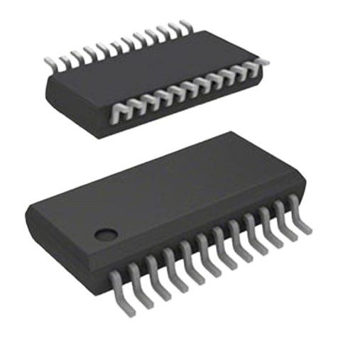
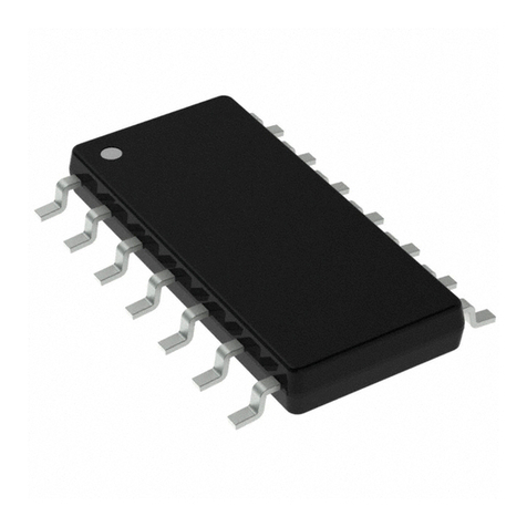
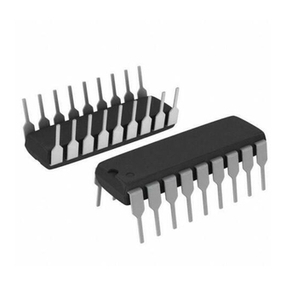
• Packagetypes:16-pinNSOP/DIP

Rev. 1.00 6 June 19, 2014 Rev. 1.00 7 June 19, 2014
HT46R003B
Cost-Effective A/D 8-bit OTP MCU
HT46R003B
Cost-Effective A/D 8-bit OTP MCU
General Description
Thedeviceis8-bithighperformanceRISCarchitecturemicrocontrollerdevicespecicallydesigned
forawiderangeofapplications.Theadvantagesoflowpowerconsumption,I/Oexibility,timer
functions,oscillatoroptions,HALTandwake-upfunctions,watchdogtimer,aswellaslowcost,
enhancetheversatilityofthedevicetosuitforawiderangeoftheI/OandA/Dcontrolapplication
possibilitiessuchasindustrialcontrol,consumerproductsandsubsystemcontrollers,etc.
Block Diagram
8-bit
RISC
MCU
Core
Time
Base
A/D
Converter
I/O
Ports
Interrupt
Controller
Reset
Circuit
Internal RC
Oscillators
8-bit
Timer
Watchdog
Timer
Low Voltage
Reset
RAM
Data
Memory
PWM
Driver
PFD
Driver
OTP
Program
Memory
Pin Assignment
16
15
14
13
12
11
10
9
1
2
3
4
5
6
7
8
HT46R003B
16 NSOP-A/DIP-A
PA3/AN3
PA2/AN2
PA1/AN1
PA0/AN0
VSS
PB0
PB1
PB2
PA4/PWM
PA5/AN4
PA6/INT
PA7/RES
VDD
PB5/PFD
PB4/TMR
PB3

Rev. 1.00 6 June 19, 2014 Rev. 1.00 7 June 19, 2014
HT46R003B
Cost-Effective A/D 8-bit OTP MCU
HT46R003B
Cost-Effective A/D 8-bit OTP MCU
Pin Description
Pin Name Function OPT I/T O/T Description
PA0/AN0 PA0 PAPU
PAWU ST CMOS General purpose I/O. Register enabled pull-up and wake-up.
AN0 ADPCR AN — Analog input channel 0
PA1/AN1 PA1 PAPU
PAWU ST CMOS General purpose I/O. Register enabled pull-up and wake-up.
AN1 ADPCR AN — Analog input channel 1
PA2/AN2 PA2 PAPU
PAWU ST CMOS General purpose I/O. Register enabled pull-up and wake-up.
AN2 ADPCR AN — Analog input channel 2
PA3/AN3 PA3 PAPU
PAWU ST CMOS General purpose I/O. Register enabled pull-up and wake-up.
AN3 ADPCR AN — Analog input channel 3
PA4/PWM PA4 PAPU
PAWU ST CMOS General purpose I/O. Register enabled pull-up and wake-up.
PWM CTRL0 — CMOS PWM output
PA5/AN4 PA5 PAPU
PAWU ST CMOS General purpose I/O. Register enabled pull-up and wake-up.
AN4 ADPCR AN — Analog input channel 4
PA6/INT
PA6 PAPU
PAWU ST CMOS General purpose I/O. Register enabled pull-up and wake-up.
INT INTC0
CTRL1 ST — External interrupt input
PA7/RES PA7 PAWU
EXTRESB ST NMOS General purpose I/O. Register enabled wake-up.
RES EXTRESB ST — Reset input
PB0~PB3 PB0~PB3 PBPU ST CMOS General purpose I/O. Register enabled pull-up.
PB4/TMR PB4 PBPU ST CMOS General purpose I/O. Register enabled pull-up.
TMR TMRC ST — Timer/Event counter input
PB5/PFD PB5 PBPU ST CMOS General purpose I/O. Register enabled pull-up.
PFD CTRL0 — CMOS PFD output
VDD VDD — PWR — Power supply
VSS VSS — PWR — Ground
Note:I/T:Inputtype; O/T:Outputtype;
OPT:Optionalbyregisteroption;
PWR:Power; AN:Analogsignal;
ST:SchmittTriggerinput;
CMOS:CMOSoutput;
NMOS:NMOSoutput

Rev. 1.00 8 June 19, 2014 Rev. 1.00 9 June 19, 2014
HT46R003B
Cost-Effective A/D 8-bit OTP MCU
HT46R003B
Cost-Effective A/D 8-bit OTP MCU
Absolute Maximum Ratings
SupplyVoltage................................................................................................VSS-0.3VtoVSS+6.0V
InputVoltage.................................................................................................. VSS-0.3VtoVDD+0.3V
StorageTemperature.................................................................................................... -50°Cto125°C
OperatingTemperature.................................................................................................. -40°Cto85°C
Note:Thesearestressratingsonly.Stressesexceedingtherangespecifiedunder“Absolute
MaximumRatings”maycausesubstantialdamagetothedevice.Functionaloperationofthis
deviceatotherconditionsbeyondthoselistedinthespecicationisnotimpliedandprolonged
exposuretoextremeconditionsmayaffectdevicereliability.
D.C. Characteristics
Ta=25°C
Symbol Parameter Test Conditions Min. Typ. Max. Unit
VDD Conditions
VDD Operating voltage — fSYS=8MHz 2.3 — 5.5 V
IDD
Operating current
(HIRC on)
3V No load, fSYS=8MHz
A/D Converter disable
—1.2 1.8 mA
5V — 2.4 3.6 mA
ISTB
Standby current
(LIRC on)
3V No load, System halt — — 5 μA
5V — — 10 μA
Standby current
(LIRC off)
3V No load, System halt — — 1 μA
5V — — 2μA
VIL
Input Low Voltage for I/O ports, TMR, INT 5V —0 — 1.5 V
— 0 — 0.2VDD V
Input low voltage for RES pin — — 0 — 0.4VDD V
VIH
Input High Voltage for I/O ports, TMR, INT 5V —3.5 — 5 V
— 0.8VDD — VDD V
Input high voltage for RES pin — — 0.9VDD — VDD V
VLVR Low Voltage Reset voltage — LVR enable,
voltage select 2.1V 2.0 2.1 2.2 V
IOH Source current for I/O ports 3V VOH=0.9VDD
-2.5 -5 — mA
5V -5 -11 — mA
IOL
Sink current for I/O ports 3V VOL=0.1VDD
7.5 15 — mA
5V 15 30 — mA
Sink current for PA7 pin 5V VOL=0.1VDD 2 3 — mA
RPH Pull-high resistance for I/O ports 3V — 20 60 100 kΩ
5V — 10 30 50 kΩ

Rev. 1.00 8 June 19, 2014 Rev. 1.00 9 June 19, 2014
HT46R003B
Cost-Effective A/D 8-bit OTP MCU
HT46R003B
Cost-Effective A/D 8-bit OTP MCU
A.C. Characteristics
Ta=25°C
Symbol Parameter Test Conditions Min. Typ. Max. Unit
VDD Conditions
fSYS System clock 2.3V~5.5V — 8 MHz
fHIRC System clock (HIRC)
3V/5V Ta=25°C -2% 8 +2% MHz
3V/5V Ta=0°C~70°C -5% 8 +5% MHz
3.0V~5.5V Ta=0°C~70°C -8% 8 +8% MHz
3.0V~5.5V Ta=-40°C~85°C -12% 8 +12% MHz
fTIMER Timer I/P frequency (TMR) 3.3V~5.5V — 0 — 8 MHz
tWDTOSC Watchdog oscillator period 3V — 45 90 180 μs
5V — 32 65 130 μs
tRES External reset low pulse width — — 1 — — μs
tRESF External reset low pulse width (with lter) — — — 150 — ns
tSST System start-up timer period — Wake-up from halt — 16 — tSYS
tLVR Low Voltage Width to Reset — — 0.25 1 2 ms
tRSD System Reset Delay Time (All Reset) — — 25 50 100 ms
Note:1.tSYS=1/fSYS
2.TomaintaintheaccuracyoftheinternalHIRCoscillatorfrequency,a0.1μFdecouplingcapacitorshould
beconnectedbetweenVDDandVSSandlocatedasclosetothedeviceaspossible.
A/D Converter Characteristics
Ta=25°C
Symbol Parameter Test Conditions Min. Typ. Max. Unit
VDD Conditions
AVDD Analog operating voltage — VREF=VDD 2.7 — 5.5 V
VAD A/D Input Voltage — — 0 — AVDD /VREF V
DNL A/D Differential Non-linearity
2.7V
VREF=VDD=AVDD
tAD=0.5μs-2 — +2 LSB3V
5V
INL A/D Integral non-linearity
2.7V
VREF=VDD=AVDD
tAD=0.5μs-4 — +4 LSB3V
5V
IADC
Additional Power Consumption if
A/D Converter is used
3V No load (tAD=0.5μs) — 0.5 — mA
5V — 0.6 — mA
tAD A/D Converter Clock Period 2.7V~5.5V — 0.5 — 10 μs
tADC
A/D Conversion Time
(Include Sample and Hold Time) 2.7V~5.5V 12-bit A/D Converter — 16 — tAD
tON2ST A/D Converter On-to-Start Time 2.7V~5.5V — 2 — — μs
Note:A/Dconversiontime(tAD)=n(bitsADC)+4(samplingtime),theconversionforeachbitneedsoneADC
clock(tAD).

Rev. 1.00 10 June 19, 2014 Rev. 1.00 11 June 19, 2014
HT46R003B
Cost-Effective A/D 8-bit OTP MCU
HT46R003B
Cost-Effective A/D 8-bit OTP MCU
Power-on Reset Characteristics
Ta=25°C
Symbol Parameter Test Conditions Min. Typ. Max. Unit
VDD Conditions
VPOR VDD Start Voltage to Ensure Power-on Reset — — — — 100 mV
RRVDD VDD Raising Rate to Ensure Power-on Reset — — 0.035 — — V/ms
tPOR
Minimum Time for VDD Stays at VPOR to
Ensure Power-on Reset — — 1 — — ms
V
DD
t
POR
RR
VDD
V
POR
Time
System Architecture
Akeyfactorinthehigh-performancefeaturesoftheHoltekrangeofmicrocontrollersisattributed
totheinternalsystemarchitecture.Therangeofdevicetakeadvantageoftheusualfeaturesfound
withinRISCmicrocontrollersprovidingincreasedspeedofoperationandenhancedperformance.
Thepipeliningschemeisimplementedinsuchawaythatinstructionfetchingandinstruction
executionareoverlapped,henceinstructionsareeffectivelyexecutedinonecycle,withthe
exceptionofbranchorcallinstructions.An8-bitwideALUisusedinpracticallyalloperations
oftheinstructionset.Itcarriesoutarithmeticoperations,logicoperations,rotation,increment,
decrement,branchdecisions,etc.Theinternaldatapathissimpliedbymovingdatathroughthe
AccumulatorandtheALU.CertaininternalregistersareimplementedintheDataMemoryand
canbedirectlyorindirectlyaddressed.Thesimpleaddressingmethodsoftheseregistersalong
withadditionalarchitecturalfeaturesensurethataminimumofexternalcomponentsisrequiredto
provideafunctionalI/OandA/Dsystemwithmaximumreliabilityandexibility.
Clocking and Pipelining
Themainsystemclock,derivedfromHIRCoscillatorissubdividedintofourinternallygenerated
non-overlappingclocks,T1~T4.TheProgramCounterisincrementedatthebeginningoftheT1
clockduringwhichtimeanewinstructionisfetched.TheremainingT2~T4clockscarryoutthe
decodingandexecutionfunctions.Inthisway,oneT1~T4clockcycleformsoneinstructioncycle.
Althoughthefetchingandexecutionofinstructionstakesplaceinconsecutiveinstructioncycles,the
pipeliningstructureofthemicrocontrollerensuresthatinstructionsareeffectivelyexecutedinone
instructioncycle.TheexceptiontothisareinstructionswherethecontentsoftheProgramCounter
arechanged,suchassubroutinecallsorjumps,inwhichcasetheinstructionwilltakeonemore
instructioncycletoexecute.
Forinstructionsinvolvingbranches,suchasjumporcallinstructions,twoinstructioncyclesare
requiredtocompleteinstructionexecution.Anextracycleisrequiredastheprogramtakesone
cycletorstlyobtaintheactualjumporcalladdressandthenanothercycletoactuallyexecutethe
branch.Therequirementforthisextracycleshouldbetakenintoaccountbyprogrammersintiming
sensitiveapplications.

Rev. 1.00 10 June 19, 2014 Rev. 1.00 11 June 19, 2014
HT46R003B
Cost-Effective A/D 8-bit OTP MCU
HT46R003B
Cost-Effective A/D 8-bit OTP MCU
System Clocking and Pipelining
Instruction Fetching
Program Counter – PC
Duringprogramexecution,theProgramCounterisusedtokeeptrackoftheaddressofthenext
instructiontobeexecuted.Itisautomaticallyincrementedbyoneeachtimeaninstructionis
executedexceptforinstructions,suchas“JMP”or“CALL”thatdemandajumptoanon-consecutive
ProgramMemoryaddress.Itmustbenotedthatonlythelower8bits,knownastheProgram
CounterLowRegister,aredirectlyaddressablebyuser.
Whenexecutinginstructionsrequiringjumpingtonon-consecutiveaddressessuchasajump
instruction,asubroutinecall,interruptorreset,etc,themicrocontrollermanagesprogramcontrol
byloadingtherequiredaddressintotheProgramCounter.Forconditionalskipinstructions,once
theconditionhasbeenmet,thenextinstruction,whichhasalreadybeenfetchedduringthepresent
instructionexecution,isdiscardedandadummycycletakesitsplacewhilethecorrectinstructionis
obtained.
Program Counter
High Byte of Program Low Byte of Program
PC9~PC8 PCL7~PCL0
ThelowerbyteoftheProgramCounter,knownastheProgramCounterLowregisterorPCL,is
availableforprogramcontrolandisareadableandwriteableregister.Bytransferringdatadirectly
intothisregister,ashortprogramjumpcanbeexecuteddirectly.However,asonlythislowbyte
isavailableformanipulation,thejumpsarelimitedinthepresentpageofmemory,whichhave
256locations.Whensuchprogramjumpsareexecuteditshouldalsobenotedthatadummycycle
willbeinserted.ThelowerbyteoftheProgramCounterisfullyaccessibleunderprogramcontrol.
ManipulatingthePCLmightcauseprogrambranching,soanextracycleisneededtopre-fetch.

Rev. 1.00 12 June 19, 2014 Rev. 1.00 13 June 19, 2014
HT46R003B
Cost-Effective A/D 8-bit OTP MCU
HT46R003B
Cost-Effective A/D 8-bit OTP MCU
Stack
ThisisaspecialpartofthememorywhichisusedtosavethecontentsoftheProgramCounteronly.
Thedevicestackisorganizedinto4levelsandneitherpartofthedatanorpartoftheprogramspace,
andisneitherreadablenorwriteable.TheactivatedlevelisindexedbytheStackPointer,andis
neitherreadablenorwriteable.Atasubroutinecallorinterruptacknowledgesignal,thecontentsof
theProgramCounterarepushedontothestack.Attheendofasubroutineoraninterruptroutine,
signaledbyareturninstruction,RETorRETI,theProgramCounterisrestoredtoitspreviousvalue
fromthestack.Afteradevicereset,theStackPointerwillpointtothetopofthestack.
Program C ounter
Stack Level 1
Stack Level 2
Stack Level 3
Stack Level 4
Program
Memory
Top of S ta ck
Stack
Poin te r
Bottom o f Stack
Ifthestackisfullandanenabledinterrupttakesplace,theinterruptrequestagwillberecordedbut
theacknowledgesignalwillbeinhibited.WhentheStackPointerisdecremented,byRETorRETI,
theinterruptwillbeserviced.Thisfeaturepreventsstackoverowallowingtheprogrammertouse
thestructuremoreeasily.However,whenthestackisfull,aCALLsubroutineinstructioncanstill
beexecutedwhichwillresultinastackoverow.Precautionsshouldbetakentoavoidsuchcases
whichmightcauseunpredictableprogrambranching.
Arithmetic and Logic Unit – ALU
Thearithmetic-logicunitorALUisacriticalareaofthemicrocontrollerthatcarriesoutarithmetic
andlogicoperationsoftheinstructionset.Connectedtothemainmicrocontrollerdatabus,theALU
receivesrelatedinstructioncodesandperformstherequiredarithmeticorlogicaloperationsafter
whichtheresultwillbeplacedinthespeciedregister.AstheseALUcalculationoroperationsmay
resultincarry,borroworotherstatuschanges,thestatusregisterwillbecorrespondinglyupdatedto
reectthesechanges.TheALUsupportsthefollowingfunctions:
• Arithmeticoperations:ADD,ADDM,ADC,ADCM,SUB,SUBM,SBC,SBCM,DAA
• Logicoperations:AND,OR,XOR,ANDM,ORM,XORM,CPL,CPLA
• RotationRRA,RR,RRCA,RRC,RLA,RL,RLCA,RLC
• IncrementandDecrementINCA,INC,DECA,DEC
• Branchdecision,JMP,SZ,SZA,SNZ,SIZ,SDZ,SIZA,SDZA,CALL,RET,RETI.

Rev. 1.00 12 June 19, 2014 Rev. 1.00 13 June 19, 2014
HT46R003B
Cost-Effective A/D 8-bit OTP MCU
HT46R003B
Cost-Effective A/D 8-bit OTP MCU
Program Memory
TheProgramMemoryisthelocationwheretheusercodeorprogramisstored.Thedeviceis
suppliedwithOne-TimeProgrammable,OTP,memorywhereuserscanprogramtheirapplication
codeintothedevice.Byusingtheappropriateprogrammingtools,OTPdeviceoffersusersthe
exibilitytofreelydeveloptheirapplicationswhichmaybeusefulduringdebugorforproducts
requiringfrequentupgradesorprogramchanges.
Structure
TheProgramMemoryhasacapacityof1K×14bits.TheProgramMemoryisaddressedbythe
ProgramCounterandalsocontainsdata,tableinformationandinterruptentriesinformation.Table
data,whichcanbesetinanylocationwithintheProgramMemory,isaddressedbyseparatetable
pointerregister.
000H Initialisation Vector
004H
3FFH 14 bits
Interrupt Vectors
010H
Look-up Table
n00H
nFFH
Program Memory Structure
Special Vectors
WithintheProgramMemory,certainlocationsarereservedfortheresetandinterrupts.Thelocation
000Hisreservedforusebythedeviceresetforprograminitialisation.Afteradeviceresetis
initiated,theprogramwilljumptothislocationandbeginexecution.
Look-up Table
AnylocationwithintheProgramMemorycanbedenedasalook-uptablewhereprogrammerscan
storexeddata.Tousethelook-uptable,thetablepointermustrstbesetbyplacingtheaddress
ofthelookupdatatoberetrievedinthetablepointerregister,TBLP.Thisregisterdenesthetotal
addressofthelook-uptable.
Aftersettingupthetablepointer,thetabledatacanberetrievedfromtheProgramMemory
usingthe“TABRDC[m]”or“TABRDL[m]”instructions,respectively.Whentheinstructionis
executed,thelowerordertablebytefromtheProgramMemorywillbetransferredtotheuser
denedDataMemoryregister[m]asspeciedintheinstruction.Thehigherordertabledatabyte
fromtheProgramMemorywillbetransferredtotheTBLHspecialregister.Anyunusedbitsinthis
transferredhigherorderbytewillbereadas“0”.
Theaccompanyingdiagramillustratestheaddressingdataowofthelook-uptable.

Rev. 1.00 14 June 19, 2014 Rev. 1.00 15 June 19, 2014
HT46R003B
Cost-Effective A/D 8-bit OTP MCU
HT46R003B
Cost-Effective A/D 8-bit OTP MCU
Register T BLHUser S electe d
Register
High B yteLow B yte
TBLP R egis te r
Data
Address
14 b its
Last p age o r
TBHP R egister
Table Program Example
Theaccompanyingexampleshowshowthetablepointerandtabledataisdenedandretrievedfrom
thedevice.Thisexampleusesrawtabledatalocatedinthelastpagewhichisstoredthereusingthe
ORGstatement.ThevalueatthisORGstatementis“0300H”whichreferstothestartaddressofthe
lastpagewithinthe1KProgramMemoryofthemicrocontroller.
Thetablepointerissetheretohaveaninitialvalueof“06H”.Thiswillensurethattherstdataread
fromthedatatablewillbeattheProgramMemoryaddress“0306H”or6locationsafterthestartof
thelastpage.Notethatthevalueforthetablepointerisreferencedtotherstaddressofthepresent
pageifthe“TABRDC[m]”instructionisbeingused.Thehighbyteofthetabledatawhichinthis
caseisequaltozerowillbetransferredtotheTBLHregisterautomaticallywhenthe“TABRDL
[m]”instructionisexecuted.
BecausetheTBLHregisterisaread-onlyregisterandcannotberestored,careshouldbetaken
toensureitsprotectionifboththemainroutineandInterruptServiceRoutineusethetableread
instructions.Ifusingthetablereadinstructions,theInterruptServiceRoutinesmaychangethe
valueofTBLHandsubsequentlycauseerrorsifusedagainbythemainroutine.Asaruleitis
recommendedthatsimultaneoususeofthetablereadinstructionsshouldbeavoided.However,in
situationswheresimultaneoususecannotbeavoided,theinterruptsshouldbedisabledpriortothe
executionofanymainroutinetable-readinstructions.Notethatalltablerelatedinstructionsrequire
twoinstructioncyclestocompletetheiroperation.
Table Read Program Example
tempreg1 db ? ; temporary register #1
tempreg2 db ? ; temporary register #2
:
mov a,06h ; initialize table pointer - note that this address
; is referenced
mov tblp, a ; to the last page or present page
:
tabrdl tempreg1 ; transfers value in table referenced by table pointer
; to tempreg1
; data at prog. memory address “0306H” transferred to tempreg1
; and TBLH
dec tblp ; reduce value of table pointer by one
tabrdl tempreg2 ; transfers value in table referenced by table pointer
; to tempreg2
; data at prog. memory address “0305H” transferred to
; tempreg2 and TBLH
; in this example the data “1AH” is transferred to tempreg1 and
; data “0FH” to register tempreg2
; the value “00H” will be transferred to the high byte
; register TBLH
:
org 0300h ; sets initial address of last page
dc 00Ah, 00Bh, 00Ch, 00Dh, 00Eh, 00Fh, 01Ah, 01Bh
:

Rev. 1.00 14 June 19, 2014 Rev. 1.00 15 June 19, 2014
HT46R003B
Cost-Effective A/D 8-bit OTP MCU
HT46R003B
Cost-Effective A/D 8-bit OTP MCU
RAM Data Memory
TheDataMemoryisavolatileareaof8-bitwideRAMinternalmemoryandisthelocationwhere
temporaryinformationisstored.
Structure
Dividedintotwosections,therstoftheseisanareaofRAMwherespecialfunctionregistersare
located.Theseregistershavexedlocationsandarenecessaryforcorrectoperationofthedevice.
Manyoftheseregisterscanbereadfromandwrittentodirectlyunderprogramcontrol,however,
someremainprotectedfromusermanipulation.ThesecondareaofDataMemoryisreservedfor
generalpurposeuse.Alllocationswithinthisareaarereadandwriteaccessibleunderprogram
control.
ThetwosectionsofDataMemory,theSpecialPurposeandGeneralPurposeDataMemoryare
locatedatconsecutivelocations.AllareimplementedinRAMandare8bitswidebutthelengthof
eachmemorysectionisdictatedbythetypeofmicrocontrollerchosen.ThestartaddressoftheData
Memoryforthedeviceistheaddress“00H”.
Allmicrocontrollerprogramsrequireanareaofread/writememorywheretemporarydatacanbe
storedandretrievedforuselater.ItisthisareaofRAMmemorythatisknownasGeneralPurpose
DataMemory.ThisareaofDataMemoryisfullyaccessiblebytheuserprogramforbothreading
andwritingoperations.Byusingthe“SET[m].i”and“CLR[m].i”instructionsindividualbitscan
besetorresetunderprogramcontrolgivingtheuseralargerangeofexibilityforbitmanipulation
intheDataMemory.
Data Memory Structure
Note:MostoftheDataMemorybitscanbedirectlymanipulatedusingthe“SET[m].i”and“CLR
[m].i”withtheexceptionofafewdedicatedbits.TheDataMemorycanalsobeaccessed
viathememorypointerregisters.
Special Purpose Data Memory
ThisareaofDataMemoryiswhereregisters,necessaryforthecorrectoperationofthe
microcontroller,arestored.Mostoftheregistersarebothreadableandwriteablebutsomeare
protectedandarereadableonly,thedetailsofwhicharelocatedundertherelevantSpecialFunction
Registersection.Notethatforlocationsthatareunused,anyreadinstructiontotheseaddresseswill
returnthevalue“00H”.

Rev. 1.00 16 June 19, 2014 Rev. 1.00 17 June 19, 2014
HT46R003B
Cost-Effective A/D 8-bit OTP MCU
HT46R003B
Cost-Effective A/D 8-bit OTP MCU
00H
01H
02H
03H
IAR0
MP0
IAR1
MP1
04H
ACC
05H
PCL
06H
TBLP
07H
TBLH
08H
WDTS
09H
STATUS
0AH
INTC0
0BH
TMR
0CH
TMRC
0DH
INTC1
0EH
0FH
PA
10H
PAC
11H
PAPU
12H
PAWU
13H
PB
14H
PBC
15H
PBPU
16H
17H
18H
19H
CTRL0
1AH
CTRL1
1BH
WDTC
1CH
1DH
ADPCR
1EH
PWM0
1FH
ADRL
20H
ADRH
21H
ADCR
22H
ACSR
23H
24H EXTRESB
25H
3FH
: unused, read as 00H
Special Purpose Data Memory

Rev. 1.00 16 June 19, 2014 Rev. 1.00 17 June 19, 2014
HT46R003B
Cost-Effective A/D 8-bit OTP MCU
HT46R003B
Cost-Effective A/D 8-bit OTP MCU
Special Function Registers
Toensuresuccessfuloperationofthemicrocontroller,certaininternalregistersareimplementedin
theDataMemoryarea.Theseregistersensurecorrectoperationofinternalfunctionssuchastimer,
interrupts,etc.,aswellasexternalfunctionssuchasI/Odatacontrol.Thelocationsoftheseregisters
withintheDataMemorybeginattheaddressof“00H”.AnyunusedDataMemorylocations
betweenthesespecialfunctionregistersandthepointwheretheGeneralPurposeMemorybeginsis
reservedandattemptingtoreaddatafromtheselocationswillreturnavalueof“00H”.
Indirect Addressing Registers – IAR0, IAR1
TheIndirectAddressingRegisters,IAR0andIAR1,althoughhavingtheirlocationsinnormalRAM
register,donotactuallyphysicallyexistasnormalregisters.Themethodofindirectaddressing
forRAMdatamanipulationisusingtheseIndirectAddressingRegistersandMemoryPointers,in
contrasttodirectmemoryaddressing,wheretheactualmemoryaddressisspecified.Actionson
theIAR0andIAR1registerswillresultinnoactualreadorwriteoperationtotheseregistersbut
rathertothememorylocationspeciedbytheircorrespondingMemoryPointers,MP0orMP1.As
theIndirectAddressingRegistersarenotphysicallyimplemented,readingtheIndirectAddressing
Registersindirectlywillreturnaresultof“00H”andwritingtotheregistersindirectlywillresultin
nooperation.
Memory Pointers – MP0, MP1
TwoMemoryPointers,knownasMP0andMP1areprovided.TheseMemoryPointersare
physicallyimplementedintheDataMemoryandcanbemanipulatedinthesamewayasnormal
registersprovidingaconvenientwaywithwhichtoindirectlyaddressandtrackdata.Whenany
operationtotherelevantIndirectAddressingRegistersiscarriedout,theactualaddresswhichthe
microcontrollerisdirectedtoistheaddressspeciedbytherelatedMemoryPointer.Notethatfor
thisdevice,theMemoryPointers,MP0andMP1,areboth8-bitregistersandusedtoaccesstheData
MemorytogetherwiththeircorrespondingindirectaddressingregistersIAR0andIAR1.
ThefollowingexampleshowshowtoclearasectionoffourDataMemorylocationsalreadydened
aslocationsadres1toadres4.
Indirect Addressing Program Example
data .section ‘data’
adres1 db ?
adres2 db ?
adres3 db ?
adres4 db ?
block db ?
code. section at 0 code
org 00h
start:
mov a,04h ; set size of block
mov block,a
mov a,offsetadres1 ;AccumulatorloadedwithrstRAMaddress
mov mp0,a ;setmemorypointerwithrstRAMaddress
loop:
clr IAR0 ;clearthedataataddressdenedbyMP0
inc mp0 ; increment memory pointer
sdz block ; check if last memory location has been cleared
jmp loop
continue:
Theimportantpointtonotehereisthatintheexampleshownabove,noreferenceismadetospecic
DataMemoryaddresses.

Rev. 1.00 18 June 19, 2014 Rev. 1.00 19 June 19, 2014
HT46R003B
Cost-Effective A/D 8-bit OTP MCU
HT46R003B
Cost-Effective A/D 8-bit OTP MCU
Accumulator – ACC
TheAccumulatoriscentraltotheoperationofanymicrocontrollerandiscloselyrelatedwith
operationscarriedoutbytheALU.TheAccumulatoristheplacewhereallintermediateresults
fromtheALUarestored.WithouttheAccumulatoritwouldbenecessarytowritetheresultof
eachcalculationorlogicaloperationsuchasaddition,subtraction,shift,etc.,totheDataMemory
resultinginhigherprogrammingandtimingoverheads.Datatransferoperationsusuallyinvolve
thetemporarystoragefunctionoftheAccumulator;forexample,whentransferringdatabetween
oneuser-definedregisterandanother,itisnecessarytodothisbypassingthedatathroughthe
Accumulatorasnodirecttransferbetweentworegistersispermitted.
Program Counter Low Register – PCL
Toprovideadditionalprogramcontrolfunctions,thelowbyteoftheProgramCounterismade
accessibletoprogrammersbylocatingitwithintheSpecialPurposeareaoftheDataMemory.By
manipulatingthisregister,directjumpstootherprogramlocationsareeasilyimplemented.Loading
avaluedirectlyintothisPCLregisterwillcauseajumptothespeciedProgramMemorylocation,
howeverastheregisterisonly8-bitwideonlyjumpswithinthecurrentProgramMemorypageare
permitted.Whensuchoperationsareused,notethatadummycyclewillbeinserted.
Status Register – STATUS
This8-bitregistercontainsthezeroag(Z),carryag(C),auxiliarycarryag(AC),overowag
(OV),powerdownag(PDF),andwatchdogtime-outag(TO).Thesearithmetic/logicaloperation
andsystemmanagementagsareusedtorecordthestatusandoperationofthemicrocontroller.
WiththeexceptionoftheTOandPDFags,bitsinthestatusregistercanbealteredbyinstructions
likemostotherregisters.AnydatawrittenintothestatusregisterwillnotchangetheTOorPDFag.
Inaddition,operationsrelatedtothestatusregistermaygivedifferentresultsduetothedifferent
instructionoperations.TheTOagcanbeaffectedonlybyasystempower-up,aWDTtime-outor
byexecutingthe“CLRWDT”or“HALT”instruction.ThePDFagisaffectedonlybyexecuting
the“HALT”or“CLRWDT”instructionorduringasystempower-up.
TheZ,OV,ACandCagsgenerallyreectthestatusofthelatestoperations.
Inaddition,onenteringaninterruptsequenceorexecutingasubroutinecall,thestatusregisterwill
notbepushedontothestackautomatically.Ifthecontentsofthestatusregistersareimportantand
ifthesubroutinecancorruptthestatusregister,precautionsmustbetakentocorrectlysaveit.Note
thatbits0~3oftheSTATUSregisterarebothreadableandwriteablebits.

Rev. 1.00 18 June 19, 2014 Rev. 1.00 19 June 19, 2014
HT46R003B
Cost-Effective A/D 8-bit OTP MCU
HT46R003B
Cost-Effective A/D 8-bit OTP MCU
STATUS Register
Bit76543210
Name — — TO PDF OV Z AC C
R/W — — R/W R/W R/W R/W R/W R/W
POR — — 0 0 x x x x
“x”: unknown
Bit7~6 Unimplemented,readas“0”
Bit5 TO:WatchdogTime-Outag
0:Afterpoweruporexecutingthe“CLRWDT”or“HALT”instruction
1:Awatchdogtime-outoccurred.
Bit4 PDF:Powerdownag
0:Afterpoweruporexecutingthe“CLRWDT”instruction
1:byexecutingthe“HALT”instruction
Bit3 OV:Overowag
0:Nooverow
1:Anoperationresultsinacarryintothehighest-orderbitbutnotacarryoutofthe
highest-orderbitorviceversa.
Bit2 Z:Zeroag
0:Theresultofanarithmeticorlogicaloperationisnotzero
1:Theresultofanarithmeticorlogicaloperationiszero
Bit1 AC:Auxiliaryag
0:Noauxiliarycarry
1:Anoperationresultsinacarryoutofthelownibblesinaddition,ornoborrow
fromthehighnibbleintothelownibbleinsubtraction
Bit0 C:Carryag
0:Nocarryout
1:Anoperationresultsinacarryduringanadditionoperationorifaborrowdoes
nottakeplaceduringasubtractionoperation
Cisalsoaffectedbyarotatethroughcarryinstruction.

Rev. 1.00 20 June 19, 2014 Rev. 1.00 21 June 19, 2014
HT46R003B
Cost-Effective A/D 8-bit OTP MCU
HT46R003B
Cost-Effective A/D 8-bit OTP MCU
System Control Registers – CTRL0, CTRL1
TheseregistersareusedtoprovidecontrolinternalfunctionssuchasthePFDfunction,thePWM
function,externalinterruptedgetriggertypeselectionandTimeBasefunctiondivisionratio.
CTRL0 Register
Bit76543210
Name — — PWMSEL — PWMC PFDC — —
R/W — — R/W — R/W R/W — —
POR — — 0 — 0 0 — —
Bit7~6 Unimplemented,readas"0"
Bit5 PWMSEL:PWMtypeselection
0:6+2
1:7+1
Bit4 Unimplemented,readas"0"
Bit3 PWMC:I/OorPWMselection
0:PA4
1:PWM
Bit2 PFDC:I/OorPFDselection
0:PB5
1:PFD
Bit1~0 Unimplemented,readas"0"
CTRL1 Register
Bit76543210
Name INTES1 INTES0 TBSEL1 TBSEL0 — — — —
R/W R/W R/W R/W R/W — — — —
POR 1 0 0 0 — — — —
Bit7~6 INTES1~INTES0:Externalinterruptedgetypeselection
00:Disable
01:Risingedgetrigger
10:Fallingedgetrigger
11:Dualedgetrigger
Bit5~4 TBSEL1~TBSEL0:Timebaseperiodselection
00:210×(1/fS)
01:211×(1/fS)
10:212×(1/fS)
11:213×(1/fS)
Bit3~0 Unimplemented,readas"0"
Table of contents
Other Holtek Microcontroller manuals

Holtek
Holtek HT32F52243 User manual

Holtek
Holtek BS86DH12C User manual

Holtek
Holtek HT32F54231 User manual

Holtek
Holtek BS83A04C User manual

Holtek
Holtek HT66F60A User manual

Holtek
Holtek HT16C22 Instructions for use

Holtek
Holtek HT46RU75D-1 User manual

Holtek
Holtek HT32 MCU User manual

Holtek
Holtek BS83B24C User manual

Holtek
Holtek HT46R46 User manual

Holtek
Holtek HT32 User manual

Holtek
Holtek HT49RU80 User manual

Holtek
Holtek HT66F20-1 User manual

Holtek
Holtek HT45F23A User manual

Holtek
Holtek HT66FM5340 User manual

Holtek
Holtek HT48R10A-1 User manual

Holtek
Holtek HT46RU66 User manual

Holtek
Holtek BC66F2332-1 User manual

Holtek
Holtek BS83B08-3 User manual

Holtek
Holtek HT45R36 Reference manual