HOMCOM 712-048 Installation guide

ASSEMBLY & INSTRUCTION MANUAL
INcwb071_US_CA
712-048
IMPORTANT, RETAIN FOR FUTURE REFERENCE: READ CAREFULLY

BEFORE using the Knee Scooter,read this manual and save for future refer-
ence.
DO NOT attempt to adjust or operate Knee Walker without carefully reading
all instructions in this manual.
Check ALL parts for shipping damage before use.In the case of shipping
damage, Do NOT USE.
Do NOT install or use this equipment without first reading and understanding
this instruction sheet.
If you are unable to understand the warnings, cautions or instructions,contact
a healthcare professional.
Attempting to install this equipment - Otherwise, injury or damage may occur.
Before using the Knee Walker, you should be trained by a healthcare profes-
sional or dealer.
Do NOT use the Knee Scooter by yourself until you have been properly
trained, you have practiced with someone and you feel confident you can
maneuver by yourself.
The user should ALWAYS consult with his/her physician or therapist to deter-
mine proper adjustment and usage.
Maximum Weight Capacity is 300 lbs. DO NOT exceed the maximum weight
capacity (including basket contents) or serious injury could result.
Maximum weight capacity for the Knee Scooter basket is 10 lbs.
DO NOT use the Knee Scooter on stairs, curbs, obstacles, etc. Serious risk of
fall or injury may occur.
Watch out for: cords, thrown rugs, toys on the floor, spilled water or oil.
DO NOT use the Knee Walker if the brake system is not working properly.
DO NOT use the Knee Walker unless all parts are secure and moving parts
are in good working order.
DO NOT lean forward, backward, or to either side while using.
DO NOT use the Knee Scooter unless seat lock lever is securely locked into
place.
DO NOT lean forward while applying the brakes.
DO NOT perform any adjustments to the Knee Scooter while it is in use
DO NOT use the seat to transport people or objects.
While it is being transported in a vehicle.
DO NOT sit on the knee rest.
DO NOT hang anything from the Knee Scooter handles or frame at any time.
This may cause the Knee Scooter to tip, resulting in bodily injury or Knee
Scooter damage. Items should be placed in the basket.
CAUTION
WARNINGS & SAFETY INSTRUCTIONS
2

DO NOT attempt to reach objects while using the Knee Scooter. Reaching for
these objects will cause a change of the weight distribution and may tip over,
resulting in injury or damage.
DO NOT walk backwards while using the Knee Scooter.
All wheels MUST be in contact with the floor at all times during use. This will
ensure the Knee Scooter is properly balanced.
Always keep both hands on the handle grips when in use.
Only use accessories and spare parts authorized by ourself.
When turning the Knee Scootker, exercise caution and only turn while at a
slow rate of movement.
The Knee Scooter is for individual use only. DO NOT attempt to push the
Knee Scooter while someone is seated on the seat. Doing so may result in
serious injury and damage to the Knee Scooter.
The Knee Scooter is not to be used as a transportation device. The Knee
Scooter is a walking aid only.
A physical/occupational therapist should assist in the height adjustments of
the Knee Scooter for maximum support and correct brake activation.
Clean with damp cloth and non-abrasive cleanser.
Clean wheels with warm water and mild cleanser. Dry with clean rag.
Ensure that all attached hardware and seat lever are secure at all times.
Inspect the Knee Scooter periodically to ensure the brakes, seat lever, steer-
ing, and wheels are functioning properly and that all parts are secure.
Replace any broken, damaged or worn items immediately.
Ensure that the brakes are working correctly. Over time the brake cables may
stretch with use, they can be adjusted by a qualified mechanic. Failure to do
this may result in injury to the user
CARE & MAINTENANCE
3

PARTS INCLUDED
A. Main Frame
C. Seat Post
E. Front Pneumatic Tire Assembly
F. Foot Pad
H. Basket Mounting Hardware
with Allen Wrench
I. 4 Pentagram Knobs
B. Gelled Seat Cushion
D. Steering Column
G. Calf Pad and Wing Knob
4

INTRODUCTION
Dual Brake
Seat
Steering
Column
Large
Pentagram
Knob
Rear 10 PU
wheel
Calf Pad
Footrest
Pad
Bag
Steering
Column
Locking
Mechanism
Front 10
PU wheel
Large
Pentagram
Knob
Wheel Axle Bolts
Frame Locking Mechanism
Drum Brake
Calf
Pad
Mount
5

ASSEMBLY
LOCKING THE MAIN FRAME
1a. Remove all packing materials and set the knee scooter
standing on it’s rear wheels and the leg rest bar.
1b. Lift up the front frame in order to connect with the rear
frame. Be cautious not to place your hand or any object
between the two frame pieces.
1c. Fully extend the frame to straighten, the hinge pin will
lock into place.
6
1d. Ensure the frame fully extended and the locking pin is
locked into place.
1e. Slide the frame lever onto the slot in the other direction
tothe front side of the frame.
1f. Rotate the frame lever so it points sideways.
1g. Press the lever firmly down until it is locked in place. No
rattling should occur after locking the mechanism at this
time.
1h. To fold the frame-reverse the procedure.
1 i. Squeeze the frame lever and the side of the front frame
to disengage the frame locking pin.
1d 1e
1f 1g
i1h1
7

2. Insert the front wheel assembly into the bottom tube of
the steering column. Align hole in wheel assembly with the
post.
Insert the pentagram knob screw through the holes tighten
pentagram knob by turning it clockwise to secure.
3a. Raise the steering column to it’s upright position, lock in
with the lever pin. The lever mechanism is same as attach-
ing two center frames together.
INSTALL THE FRONT WHEELS
INSTALL THE HANDLE BAR
8

3b 3c
3d 3e
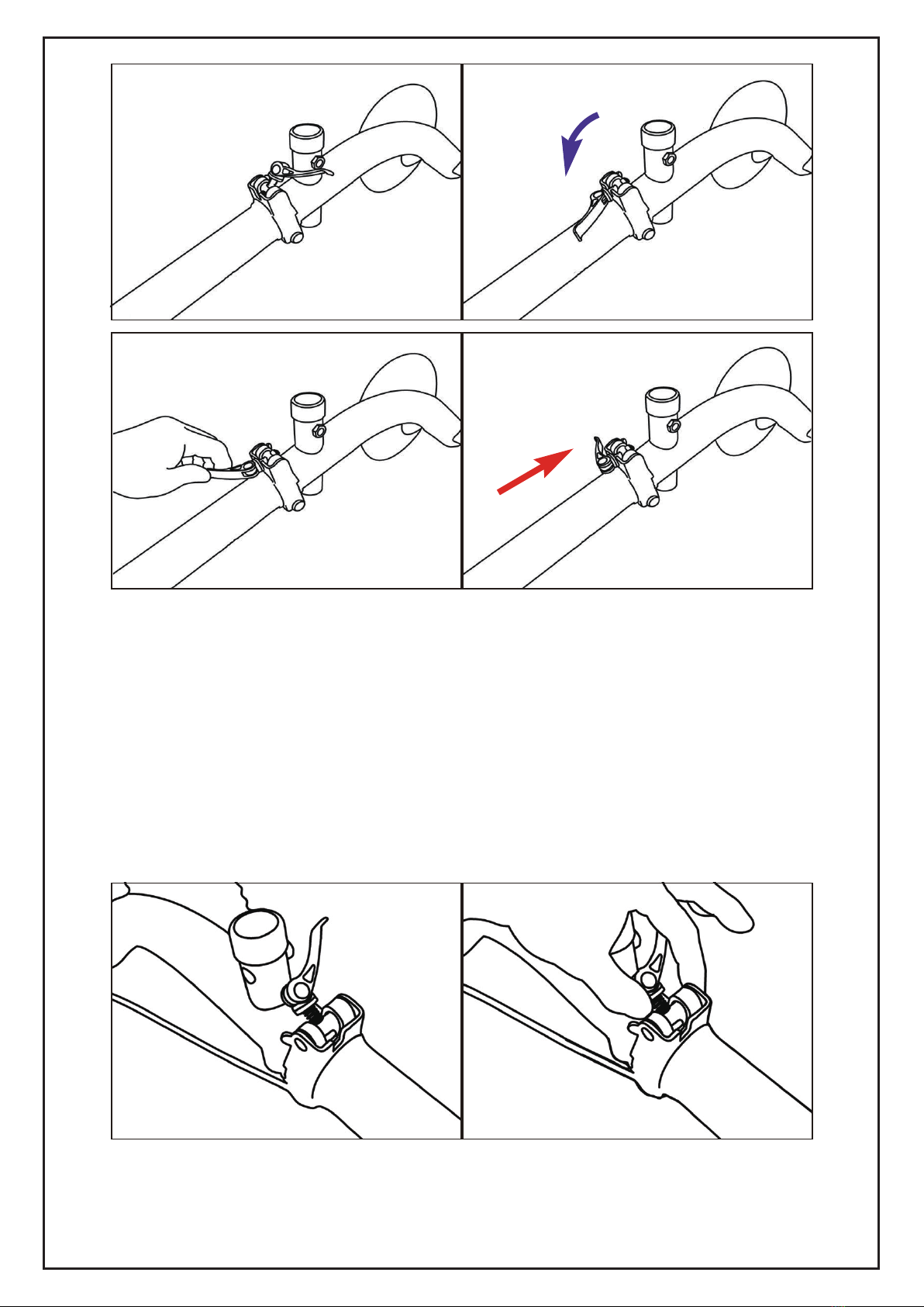
3b. Push the steering column upward until it is in the full
upright position.
3c. Rotate the steering column lever from bottom of the
column to the top side.
3d. Pull the locking mechanism up so that the circular pad
rests on top of the steering column folding hinge cutout.
3e. Push the lever down so the end of the lever is pointing
towards the ground to lock the steering column in the up-
right position.
9

3f. To fold the scooter, unfold the lever, and push the pin out
away from the slot.
3g. Lasty, squeeze in the lever in order to release the hinge
pin.
3h. Handlebars should be set at wrist level to keep your
back straight. Turn the pentagram knob counter clockwise to
remove, extend the steering shaft up or down to desired
height. Align holes in tiller, then insert the pentagram knob
screw through the steering tiller. Tighten pentagram knob by
turning it clockwise to secure.
10
Table of contents
Languages:
Other HOMCOM Bicycle manuals

HOMCOM
HOMCOM 370-027 User manual

HOMCOM
HOMCOM 370-188V80 User manual

HOMCOM
HOMCOM 370-095 User manual

HOMCOM
HOMCOM 370-191 User manual

HOMCOM
HOMCOM 370-155 User manual

HOMCOM
HOMCOM 370-182 User manual

HOMCOM
HOMCOM 370-207 User manual

HOMCOM
HOMCOM 370-205 User manual

HOMCOM
HOMCOM 370-092 User manual

HOMCOM
HOMCOM 370-188V90 User manual

HOMCOM
HOMCOM 370-199 User manual

HOMCOM
HOMCOM 370-211V70 User manual

HOMCOM
HOMCOM 370-225V00 User manual

HOMCOM
HOMCOM 342-007 User manual

HOMCOM
HOMCOM 53-0016 Assembly instructions

HOMCOM
HOMCOM 370-156 User manual

HOMCOM
HOMCOM 370-098 User manual

HOMCOM
HOMCOM 370-106 User manual

HOMCOM
HOMCOM 370-097 User manual

HOMCOM
HOMCOM 370-061 User manual


