manuals.online logo
Brands
  1. Home
  2. •
  3. Brands
  4. •
  5. HON
  6. •
  7. Indoor Furnishing
  8. •
  9. HON Initiate Flexconnect User manual

HON Initiate Flexconnect User manual

INSTALLATION IINSTRUCTIONS
Initiate™ FlexconnectTM ELECTRICAL SSYSTEM ((8-wwire)
42-2241
SIDE 1 OF 3 (7/01)
Connection to a power source, by a licensed electrician, and quantity of receptacles used for a given cir-
cuit must be in compliance with all national and local electrical codes. Connect a maximum of 13 recep-
tacles (12 in Canada, and fewer in certain U.S. locales) to one circuit. Consult applicable national and
local electrical codes.
Disconnect electrical connections between panels prior to removal of a mechanical connection. Ensure
that the power supply is disconnected prior to disconnecting any electrical components.
When electrical components are interconnected from one panel to another, the panels must be mechan-
ically connected per the appropriate panel-to-panel installation instructions.
Failure to observe these warnings could result in a fire or electrical shock.
WARNING
Illustration 1. General Configuration and Component Identification:
Illustration 2. Electrical Wiring Diagrams:
Component Identification: Color of terminal ends and
receptacle backs are BLACK. Component Identification: Color of terminal ends and
receptacle backs are RUST.
Power harness (24")
871224
Power harness
(30"-60") 8712XX
Notes: All electrical components
are UL Listed to UL1286
and UL183.
By pulling on terminal
housing at end of cable
assemblies, Power and
Pass-Thru harnesses can
be stretched up to 31/2".
4 hot / 2 neutral / 2 ground systems:
color of terminal ends are black.
3 hot / 3 neutral / 2 ground systems:
color of terminal ends are rust.
Pass-Thru harness (24"-60")
8711XX
Pass-Thru cable (12"-18")
8710XX
•Connect to previously installed cable.
•Stretch, as required, to proper position.
•Snap onto mounting bracket.
Illustration 7. Routing, at Base Rail Panel Junctions:
42-2241
SIDE 2 OF 3 (7/01)
Initiate™ FlexconnectTM ELECTRICAL SSYSTEM ((8-wwire)
To facilitate ease of configuration of electrical components:
• At least one power harness should be used at a Tee connection, when all 3 panels are powered.
• At least two power harnesses should be used at a Cross connection, when all 4 panels are powered.
• A power harness should be used in a panel positioned at the end of a panel run (See Illustration. 3).
• A power harness should be used in a panel, adjacent to a power pole location, into which a ceiling in-feed is to be connected.
• Power harness should be used in panels adjacent to 12" and 18" wide panels.
• When multiple 12" wide and 18" wide panels are used at a Tee or Cross junction, an additional 12" wide or 18" wide pass-thru cable is required.
• Pass-thru cables for 12" wide panels must be routed in a straight line into adjacent panels (cannot be routed at 90° angle); therefore:
• no more than one 12" wide panel should be used at 90° junction.
• no more than two 12" wide panels should be used at a Tee or Cross junction, and the two should be positioned in-line.
Power harness
If panel at the end of a run is powered,
reverse orientation of harness in last panel.
End of panel run
Engage power block onto
mounting bracket into a
snapped (locked) position.
Power block of power or
pass-through harness.
Receptacle
Fully engage receptacle
into power block, then
slide receptacle sideward
until receptacle snaps
into a locked position.
To remove receptacle,
depress locking tab
and slide receptacle
sideward to disengage,
then pull receptacle outward.
Insert a flat blade
screwdriver between
locking tab and flange
of mounting bracket;
rotate to depress lock-
ing tab and slide out-
ward.
Illustration 3. Powering Last Panel, at End of Panel Run:
Illustration 5. Power Block Removal:
Illustration 6. Receptacle Installation/Removal:
Outside to inside of
panel supports
Outside to outside
of panel supports
Pull cable to extend length to:
• Reach to adjacent connection point, and
• Prevent interference with base rail covers at corners.
Inside to inside of
panel supports Panel supports
Panel supports
Illustration 4. Power/Pass-Thru Harness Installation in Panel Base Rail Area:
Power or pass-thru harness
This terminal may be connected or not connected.
42-2241
SIDE 3 OF 3 (7/01)
Initiate™ FlexconnectTM ELECTRICAL SSYSTEM ((8-wwire)
Illustration 8. Base or Ceiling Side In-Feed Installation:
Improperly installed electrical components
can fail resulting in personal injury and/or
property damage. Connection of the in-feed
device to the power source should be per-
formed by a licensed electrician in compliance
with all national and local electrical codes.
To prevent personal injury, ensure in-feed
power is disconnected before component
installation.
WARNING
Pass in-feed cable through base
rail cover prior to connecting to
building electrical supply
180° swivel joint
Cover - install after power
in-feed and base rail
cover is in place.
Route cable to
power source (refer
to wiring diagram on
page 1 for proper
wiring connections).
Note: In-feed cable can be shortened. Remove
and reapply UL listing/schematic, near end
of cable, as needed.
Illustration 9. Ceiling In-Feed Installation into Base Rail Area using Integrated Power Pole (870071):
Note: For information regarding installation of
power poles, refer to the Power Pole
Installation Instructions.
Ceiling in-feed cable 8719
(12/18) - position power pole
into top of universal connector.
Panel support
Use wire tie to secure
in-feed cable to panel
support

Other HON Indoor Furnishing manuals

HON basyx BSXLMOL User manual

HON

HON basyx BSXLMOL User manual

HON HBXRISER User manual

HON

HON HBXRISER User manual

HON Coze Desk User manual

HON

HON Coze Desk User manual

HON 3301 User manual

HON

HON 3301 User manual

HON Ceres Use and care manual

HON

HON Ceres Use and care manual

HON PERPETUAL User manual

HON

HON PERPETUAL User manual

HON basyx HML8858 User manual

HON

HON basyx HML8858 User manual

HON HUDDLE User manual

HON

HON HUDDLE User manual

HON 105 Stack-On Unit User manual

HON

HON 105 Stack-On Unit User manual

HON Universal Screens User manual

HON

HON Universal Screens User manual

HON Ceres User manual

HON

HON Ceres User manual

HON Ceres Task Guide

HON

HON Ceres Task Guide

HON 105 FULL LENGTH PEDESTAL User manual

HON

HON 105 FULL LENGTH PEDESTAL User manual

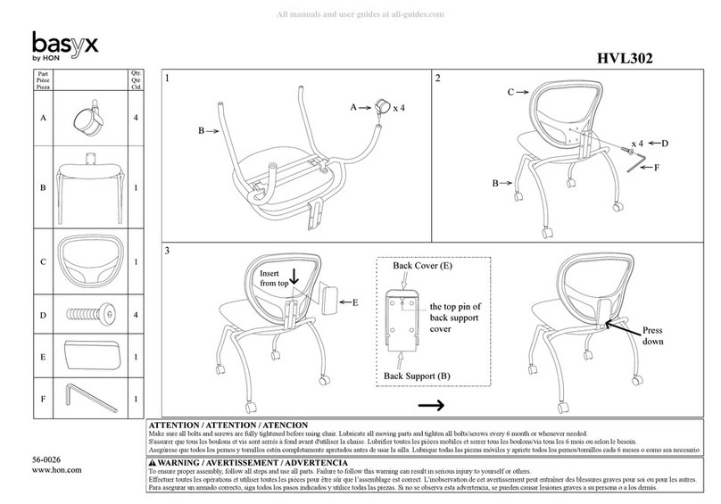
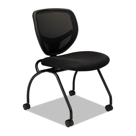
HON basyx HVL302 User manual

HON

HON basyx HVL302 User manual

HON basyx HVL302 User manual

HON

HON basyx HVL302 User manual

HON Ignition KD User manual

HON

HON Ignition KD User manual

HON Coordinate Series User manual

HON

HON Coordinate Series User manual

Popular Indoor Furnishing manuals by other brands

Forte KALOMIRA KLRK233 Assembling Instruction

Forte

Forte KALOMIRA KLRK233 Assembling Instruction

Sanus BFV145 Assembling instructions

Sanus

Sanus BFV145 Assembling instructions

popstrukt BON BON BUDDY SIDE TABLE LD02B Assembly instructions

popstrukt

popstrukt BON BON BUDDY SIDE TABLE LD02B Assembly instructions

Accora Configura Care instruction manual

Accora

Accora Configura Care instruction manual

Emerson SAM1411 Installation and use

Emerson

Emerson SAM1411 Installation and use

LTL Home Products Reflections Blaze installation instructions

LTL Home Products

LTL Home Products Reflections Blaze installation instructions

TikkTokk Nanny Panel Playpen Assembly guide

TikkTokk

TikkTokk Nanny Panel Playpen Assembly guide

Costway HW56729 user manual

Costway

Costway HW56729 user manual

baby&child INDUSTRIAL PIPE SINGLE DESK WITH DRAWERS quick start guide

baby&child

baby&child INDUSTRIAL PIPE SINGLE DESK WITH DRAWERS quick start guide

Puckdaddy Carlotta Assembly instructions

Puckdaddy

Puckdaddy Carlotta Assembly instructions

Home affaire 81322848 Assembly instructions

Home affaire

Home affaire 81322848 Assembly instructions

Costway KC54183 manual

Costway

Costway KC54183 manual

progressive automations FLT-09 user guide

progressive automations

progressive automations FLT-09 user guide

Lifetime Kidsrooms 991 1 Assembly instructions

Lifetime Kidsrooms

Lifetime Kidsrooms 991 1 Assembly instructions

Happy Babies HAPPY RW01 Assembly instructions

Happy Babies

Happy Babies HAPPY RW01 Assembly instructions

ZEITRAUM SILENT Assembly instructions

ZEITRAUM

ZEITRAUM SILENT Assembly instructions

Ticaa MANUEL H1000011507 Instructions for use

Ticaa

Ticaa MANUEL H1000011507 Instructions for use

Mocka Jack Assembly instructions

Mocka

Mocka Jack Assembly instructions

manuals.online logo
manuals.online logoBrands
  • About & Mission
  • Contact us
  • Privacy Policy
  • Terms and Conditions

Copyright 2025 Manuals.Online. All Rights Reserved.