HON Universal Screens User manual

Universal Screens
Installation Instructions
Index
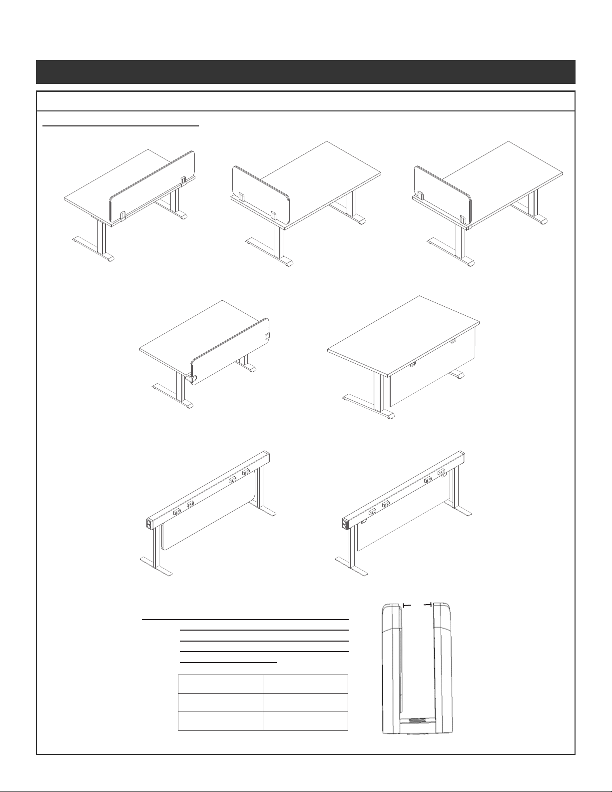
Screen Overview .................................. ............................2
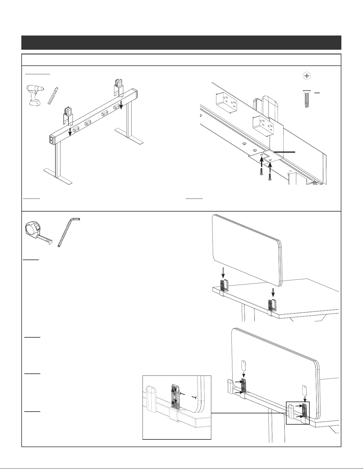
U - Bracket Installation ............................ ..........................3-6
1. Side Mount Lateral (HUSFSMB1 | HUSFSMB2)
2. Front to Back Lateral (HUSLATB1 | HUSLATB2)
3. Top Mount Lateral (HUSTOPB1 | HUSTOPB2)
4. Elevated (HUSUPMB1 | HUSUPMB2)
5. Sit on Surface (HUSSOSB1 | HUSSOSB2)
6. Empower (HUSEMPB1 | HUSEMPB2)
7. Gravitation (HUSGRVB1)
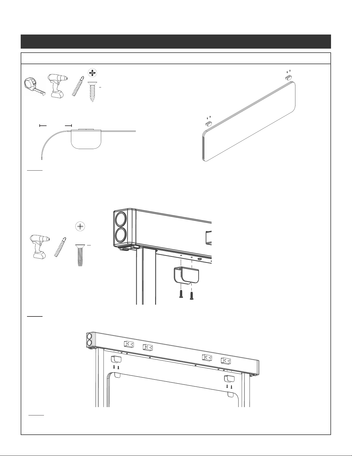
Above/Below Screens (HUSABMB1 | HUSLABF27## | HUSFABF#### | HUSAABF27##) .............7-8
Gravitation Modesty Screen - Fabric (HUSGRVB2) ..... ............................9
Gravitation Modesty Screen - Hard Surface (HUSGRVB3)..........................10
Gravitation Screen - PET (HUSGRVB5) ................. ...........................10
Modesty Screens (HUSFMOD13## | HUSLMOD13## | HUSMODB1) . ........................11-12
Alignment Clip Installation ........................ ...........................12
Hardware Chart ................................... ...........................13
Muscatine, Iowa 52761-0071
www.hon.com
Tools Needed:
1/8” Allen Wrench
Drill
Tape Measurer
#2 Phillips Driver
1/4” Hex Driver
Driver Extension
1430120100_A 07/2022

NOTE: Not all congurations shown.
Side Mount Lateral Front to Back
Above/Below Acrylic Modesty
Gravitation Fabric
Modesty
Gravitation Laminate/
Acrylic Modesty
Top Mount Lateral
Universal Screens Installation Packet
1430120100_APage 2 of 13
Screen Overview
NOTE: Most Universal Screen Bracket types
include a U-Bracket sub assembly
(shown to the right). The gap width will
vary depending on whether it is a fabric
or hard surface model.
Bracket Type A
Fabric 7/8”
Hardsurface 3/8”
A

Universal Screens Installation Packet
1430120100_A Page 3 of 13
U-Bracket Installation
NOTE: Steps 1 - 7 are applicable to all U bracket models unless otherwise noted.
Step 1 -
of the bracket.
Verify that set
inside face of
bracket.
Step 2 - Place brackets on worksurface. Brackets should be positioned so that they are approximately 6 inches in from the edge of
the screen after the screen is installed.
6”
6”

Universal Screens Installation Packet
1430120100_APage 4 of 13
U-Bracket Installation (Continued)
Step 3a - Position U-brackets in desired locations. Secure to worksurface
Tape
Top Mount Lateral
HUSTOPB1
HUSTOPB2
Step 3a - Attach tape to bottom of bracket. Mount brackets in desired
location and apply pressure for 15 seconds.
C
Select the appropriate Step 3 below for your specic bracket type. Model numbers listed as reference.
Side Mount Lateral
HUSFSMB1
HUSFSMB2
Step 3a - Align Bracket on surface and tighten (2) bottom set screws per
bracket with 1/8” Allen Wrench
Step 3a - Align Bracket on surface and tighten (2) bottom set screws per
bracket with 1/8” Allen Wrench
Front to Back Lateral
HUSLATB1
HUSLATB2
A
Note:
Top Mount Lateral brackets can
be installed using
tape OR screw method

Universal Screens Installation Packet
1430120100_A Page 5 of 13
Step 3a - Attach 2 urethane pads to the bottom of each bracket in the
approximate location shown.
Sit on Surface
HUSSOSB1
HUSSOSB2
Urethane
Pad
Elevated
HUSUPMB1
HUSUPMB2
Step 3a - Secure to surface using (4) #10 x 7/8” Hex Head wood screws
per bracket.
Step 3a - Loosen center screw using a #2 phillips driver until the bottom
and top bracket separate enough to clamp around worksurface edges.
Empower
HUSEMPB1
HUSEMPB2
B
Step 3b - Slide bracket assembly between worksurfaces and retighten
the screw to secure to the worksurfaces.
U-Bracket Installation (Continued)
Step 3b - o
then tighten screw.

Universal Screens Installation Packet
1430120100_APage 6 of 13
U-Bracket Installation (Continued)
Kerf
Line
D
Gravitation
HUSGRVB1
Step 3b - Secure brackets using (2) #8-32 x 3/4” Thread Cutting screws
per bracket.
Step 3a - Lower brackets onto beam. Bend along kerf line until holes are
aligned on the bottom of the beam.
Step 4 - Carefully insert screen into U-Bracket and ensure that
the screen is fully seated. Verify that the brackets are
positioned approximately 6” from both ends of the
screen.
Step 6 - Use 1/8” Allen wrench to tighten set
screws evenly against screen.
Step 5 -
of the U bracket and the screen on the
side with the set screws.
6”
Turn set screws
clockwise to tighten
against screen.
Step 7 - Attach magnetic covers to exposed side
of bracket.

Universal Screens Installation Packet
1430120100_A Page 7 of 13
Above/Below Screens
B
Step 1 - Slide brackets on both ends of the screen
in desired location and secure by turning
the thumb screw clockwise.
Step 2 - Position the screen in the desired location
on the worksurface. Attach mounting
brackets by installing (4) #10 x 7/8” Hex
Head screws.
Step 1 -
it is straight before securing the second bracket.
worksurfaces with (4) #10 x 7/8” Head Head Screws per bracket.
Adjustable Fabric Screens
HUSABMB1
Fixed Fabric Screens
HUSFABF####
B

Universal Screens Installation Packet
1430120100_APage 8 of 13
Step 1 - Attach (2) Mounting Brackets at pilot holes in
Arylic Panel using (4) 10-24 x 3/8” Flat Head
Machine Screws per bracket. Then attach
front cap bracket on other side of panel.
Step 2 -
then look down the edge of the panel to verify that it is
straight before securing the second bracket.
second bracket to straighten it out. Each bracket attaches
to worksurfaces with (4) #10 x 7/8” Head Head Screws per
bracket.
B
G
Step 1 - Attach (2) Brackets at pilot holes in Laminate Panel using (6) #10 x 3/4” Hex Head
Screws (H) per bracket.
Step 2 -
edge of the panel to verify that it is straight before securing the second bracket.
straighten it out. Each bracket attaches to worksurfaces with (6) #10 x 7/8” Hex
Head Screws (I) per bracket.
NOTE:
Ensure
correct
screw is
used for
each step
as to not
damage
screen
H
I
Above/Below Screens (Continued)
Laminate Screens
HUSLABF27##
Acrylic Screens
HUSAABF27##

Universal Screens Installation Packet
1430120100_A Page 9 of 13
Create
Gravitation Modesty Screen- Fabric | HUSGRVB2
1-3/4”
Step 1 - Mount small U brackets to the bottom of the fabric screen so that the edge of the bracket coincides
with the edge of the corner radius (1-3/4” in from the ends). Secure brackets by driving (2) #8-18
Flat Head Screws per bracket into the center seam of the screen.
Step 2 - Install large U brackets into bottom of Gravitation beam using
(2) #8-32 x 3/4” Thread Cutting Screws per bracket.
Step 3 - Align the small and large U brackets and slide the screen up into the beam until the magnets engage.
D
NOTE:
Do not overtighten
screws as to not
damage screen
J

Universal Screens Installation Packet
1430120100_APage 10 of 13
Gravitation Modesty Screen - Hardsurface | HUSGRVB3
Step 1 - Attach U brackets to underside of Gravitation beam using (2) #8-32 x 3/4” Thread Cutting Screws per bracket.
Step 2 - Install pins into two of the round buttons. Slide the modesty panel up into the U channel until the holes are
aligned and feed the pin through the U bracket and modesty panel until it protrudes from the opposite side.
Secure the modesty panel in place by tightening two more buttons down on the exposed end of the pin.
Thread pin into
button as shown
D
Gravitation Screen - PET | HUSGRVB5
Step 1 - Mount brackets to screen using (2)
threaded spacers and (2) threaded buttons per
bracket.
D
Step 3 - Secure brackets to beam using
(2)
#8-32 X 3/4” Thread Cutting Screws per
bracket
Step 2 - Lower screen and bracket
assembly onto beam. Bend bottom of
brackets along kerf line until holes are
aligned on the bottom of the beam.
Kerf
Line

Universal Screens Installation Packet
1430120100_A Page 11 of 13
Create
Modesty Screens
Fabric Screens
HUSFMOD13##
Step 1 -
second bracket to straighten it out. Each bracket attaches to worksurfaces with (3) #10 x 7/8” Head Head Screws
per bracket.
Step 1 - Attach (2) Brackets at pilot holes in Laminate Panel using (4) #10 x 3/4” Hex Head Screw per bracket (H).
Step 2 -
second bracket to straighten it out. Each bracket attaches to worksurfaces with (3) #10 x 7/8” Head Head
Screws per bracket (I).
B
I
H
NOTE:
Do not overtighten
screws as to not
damage screen
Laminate Screens
HUSLMOD13##

Universal Screens Installation Packet
1430120100_APage 12 of 13
Modesty Screens (Continued)
Alignment Clip Installation
Step 1 - Wedge alignment clip between the two halves of the
another screen.
Step 2 - Press screens together around alignment clip until set at
desired location.
Fabric Alignment Clip Glass Alignment Clip
Step 1 - Cap alignment over the seam where
Fabric Alignment Clip
Glass Alignment Clip
Note: Alignment Clips only applicable for in-line applications
Step 1 - Attach mounting brackets to screen using (2) #8 X 1/2” pan
head screws and (2) washers per bracket.
Step 2 -
then look down the edge of the modesty panel to verify
that it is straight before securing the second bracket. If the
bracket to straighten it out.
F
NOTE:
Do not overtighten
screws as to not
damage screen
Acrylic Modesty
HUSMODB1

Universal Screens Installation Packet
1430120100_A Page 13 of 13
Create
Hardware Chart
A1/4-20 UNC Thread
1/8” Hex Set Screw
3500106500
C#10 X 1”
Flat Head Screw
3500005000
D#8-32 X 3/4”
Thread Cutting Screw
3500005000
E#12-8 X 1”
Phillips Pan Head Screw
3500081400
F#8 X 1/2”
Phillips Pan Head Screw
3500024800
10 - 24 x 3/8”
Flat Head Machine Screw
0500320300
G
B
Hex Head Screw
0500256000
H#10 x 3/4”
Hex Head Screw
0500057900
I#10 x 7/8”
Hex Head Screw
0500256001
#8-18
Flat Head Screw
0500248400
J
Table of contents
Other HON Indoor Furnishing manuals

HON
HON basyx HML8858 User manual

HON
HON HUDDLE User manual

HON
HON Ignition KD User manual

HON
HON 105 Stack-On Unit User manual

HON
HON Ceres Use and care manual

HON
HON 105 FULL LENGTH PEDESTAL User manual

HON
HON HBXRISER User manual

HON
HON basyx HVL302 User manual

HON
HON 3301 User manual

HON
HON Ceres Task Guide
Popular Indoor Furnishing manuals by other brands

Crosswater
Crosswater UNION Series manual

Bettio
Bettio Picoplis maxi Installation, user and maintenance manual

Argos
Argos Aspley 497/6800 Assembly instructions

SEASIDE CASUAL FURNITURE
SEASIDE CASUAL FURNITURE ENVIROWOOD Adirondack Classic Swing Assembly instructions

Garth
Garth TV0630 Assembly instructions

Cooper Lighting
Cooper Lighting GRF420MH Specification sheet