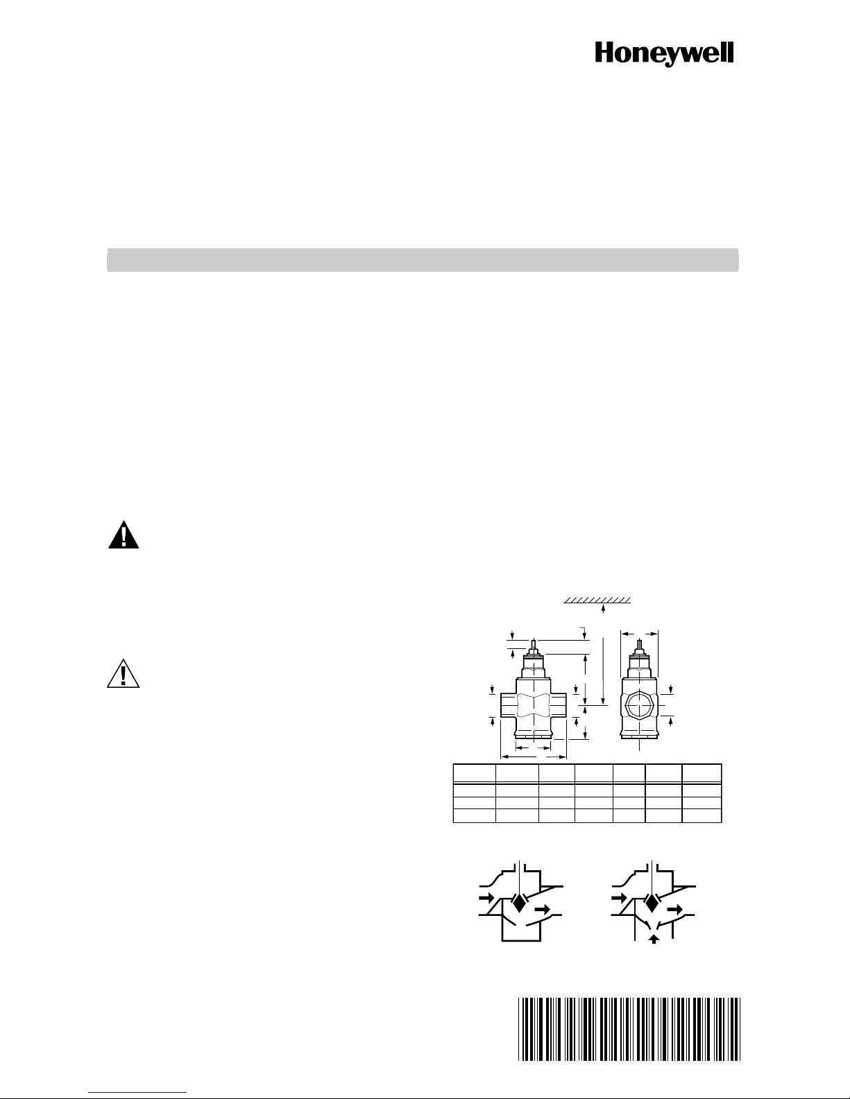
Honeywell V5852A Service manual
Other Honeywell Control Unit manuals

Honeywell
Honeywell VR4611VA1007 User manual

Honeywell
Honeywell V4043A User manual

Honeywell
Honeywell ADEMCO 5800RL Assembly instructions

Honeywell
Honeywell Notifier NFG-8 User manual

Honeywell
Honeywell NetAXS-123 User manual

Honeywell
Honeywell XW100 User manual

Honeywell
Honeywell FF-SRS5988 User manual

Honeywell
Honeywell FALCON MJ Pulse/M-Bus User manual

Honeywell
Honeywell S7800A1167 User manual

Honeywell
Honeywell RA890F Protectorelay Primary Control Installation guide

Honeywell
Honeywell MAXON 8730 Series User manual

Honeywell
Honeywell Elster Jeavons S200 User manual

Honeywell
Honeywell ModBus S7810M User manual

Honeywell
Honeywell SV2 Series User manual

Honeywell
Honeywell V5825B User manual

Honeywell
Honeywell BCU 460 Manual

Honeywell
Honeywell L5000-Wi-Fi User manual

Honeywell
Honeywell NETAXS NX4L1 User manual

Honeywell
Honeywell LCBS Connect User manual

Honeywell
Honeywell Class 500 User manual


Popular Control Unit manuals by other brands

Festo
Festo Compact Performance CP-FB6-E Brief description

Elo TouchSystems
Elo TouchSystems DMS-SA19P-EXTME Quick installation guide

JS Automation
JS Automation MPC3034A user manual

JAUDT
JAUDT SW GII 6406 Series Translation of the original operating instructions

Spektrum
Spektrum Air Module System manual

BOC Edwards
BOC Edwards Q Series instruction manual

KHADAS
KHADAS BT Magic quick start

Etherma
Etherma eNEXHO-IL Assembly and operating instructions

PMFoundations
PMFoundations Attenuverter Assembly guide

GEA
GEA VARIVENT Operating instruction

Walther Systemtechnik
Walther Systemtechnik VMS-05 Assembly instructions

Altronix
Altronix LINQ8PD Installation and programming manual