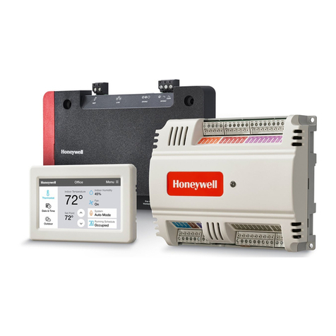
S8600B,C,H,M;S8610B,C,H,M;S8670D,E,J,KINTERMITTENTPILOT GASIGNITIONCONTROL
บริษัท เอดีดี เฟอร์เนส จํากัด
ADD FURNACE CO.,LTD.
44 ซอยบรมราชชนนี 70 ถนนบรมราชชนนี แขวงศาลาธรรมสพน์ เขตทวีวัฒนา กรุงเทพฯ 10170
โทร: 02-888-3472 โทร: ออกแบบ:08-08-170-170 แฟกซ์: 02-888-3258
https://www.add-furnace.com E-mail: sales@add-furnace.com
MAINVALVE
S8600 B,C; S8610 B,C; S8670 J,K
GND 24V
MV MV/PV PV (BRN) GND 24V
MAIN VALVE
STAGE 2
THERMOSTAT
AIRPROVINGSW ITCH
SENSE
SENSOR
3
Step 2: Verify control system ground.
Theigniter,flamesensor,andignitionmodulemustshare a common
ground with the main burner. Use thermoplastic insulated wire with
a minimum rating of 221°F (105°C)for thegroundwire;asbestos
insulationis not acceptable. If the temperature at the wire could
exceed 221°F (105°C), use a shield to protectthe wire
PILOT
1STOPERATOR
COM GROUND STAGE 1
2NDOPERATOR
R W2 W1
2
PILOT BU RNER/
from radiant heat generated by the burner. Connect the ground
wire as follows:
TWO STAGEDUAL VALVE
COMBINA TION GAS CONT ROL
4
LIMIT
CONTROLLER
COMBUS TION AIR BLOWER RELAY
IGNITER
PILOT GAS SUPPLY
a.
Fitoneendof the groundwirewithafemale1/4 in.
quick-connect terminal and connect it to the male
quick-connect GND (BURNER) terminal onthe ignition
module.
b.
Strip the other end ofthe wire and fasten it
1
L1L2 (HOT) L1 L2 COMBUSTION
(HOT) 1
AIRBLOWER
under the igniter bracket mounting screw. If nec- essary,
use a shield to protect the ground wire
1
POWER SUPPLY. PROVIDEDISCONNECT MEANSAND OVERLOAD PROTECTIONASREQUIRED.
2 ALTERNATE LIMIT CONTROLLER LOCATION.
3
MAXIMUM CABLE LENGTH 3 FT. [0.9 M].
4
CONTROLS IN 24VCIRCUIT MUST NOTBE IN GROUNDLEG TOTRANSFORMER.
from radiant heat.
c.
The burner serves as the common grounding area.If
thereisnotgoodmetal-to-metalcontact
Fig.8. S8600 B,C; S8610 B,C; S8670 J,K connections with
remote flame sensing in a heating system with a two-stage gas
control and power-assisted combustion.
CHECKOUT
Check out the gas control system:
•
Atinitialinstallationoftheappliance.
•
As part of regular maintenance procedures. Maintenance
intervals are determined by the application.See“Planning the
Installation” onpage2 formoreinformation.
•
Asthefirst stepintroubleshooting.
•
Any time work is done on thesystem.
WARNING
Fire or Explosion Hazard.
Failure to heed these warnings may cause fire or
explosion with property damage, injury, or loss of life.
1.
Ifyou smell gas or suspect a gas leak, turn off gas at
manual service valve and evacuate the building. Do
not try to light any appliance, do not touchany
electricalswitchortelephonein the building until you
are sure no spilled gas remains.
2.
Gas leak testmust be done as describedinthe steps
below on initial installation and any time workis done
involving the gas piping.
Step 1: Perform Visual Inspection.
a.
With power off,makesure allwiring connec- tions
arecleanandtight.
b.
Turnonpowertoapplianceandignitionmodule.
c.
Open manual shutoff valves in the gas line to the
appliance.
d.
Perform Gas Leak Testahead of gas control if piping
hasbeendisturbed.
GAS LEAK TEST (UPSTREAM OF GAS CONTROL)
Paint the gas control gasket edges and all pipe connections
upstream of the gas control with a rich soap and water
solution. Bubbles indicate gas leaks. Tighten the joints and
screws or replace component to stop gas leak. Recheck
with soap and water solution.
between the burner and ground, run a lead from the
burner to ground.
NOTE: Earth ground is not required.
Step 3: Review Normal Operating
Sequence and Module Specifications.
a. See “Operation” on page 8 and “Specifications” on page 2.
Step 4: Reset the Module.
a.
Turnthethermostattoitslowestsetting.
b.
Wait oneminute.
As you do the remaining steps, watch for points where operation
deviates from normal. Refer to the Troubleshooting guide on
page 15 to correct problems.
Step 5: Check Safety Shutoff Operation.
a.
Turngassupplyoff.
b.
Setthermostatorcontrollerabove roomtemper- ature to
callforheat.
c.
Watchforsparkatpilotburner eitherimmedi- atelyor
followingprepurge.Seedevicelabel.
d.
Timesparkfrom starttoshutoff.See device label.
e.
On all continuous retry models, wait 5 minutes. Ignition
sequence should start again followed by shutoff after 90
secondsmaximum.
f.
Openmanualgascockandmakesurenogasis flowing
topilotormainburner.
g.
Setthermostatbelowroomtemperatureand wait
oneminutebeforecontinuing.
Step 6: Check Normal Operation.
a.
Setthermostatorcontrollerabove roomtemper- ature to
callforheat.
b.
Makesurepilotlightssmoothlywhengas
reachesthepilotburner.
c.
Makesuremainburnerlightssmoothlywithout
flashback.
d.
Makesureburneroperatessmoothlywithout floating,
lifting, or flame rollout tothe furnace vestibule or heat
buildupinthevestibule.
e.
Perform agas leaktestintheappliance
.
