Cable entries can be made through the opening in the rear of
the subbase, or via the three surface entry break-outs in the
top and two sides of the wallplate. See fig. 2
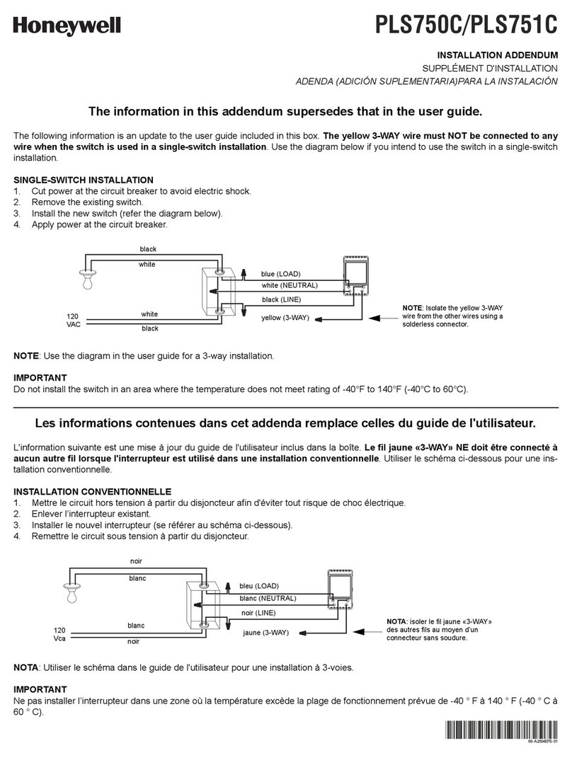
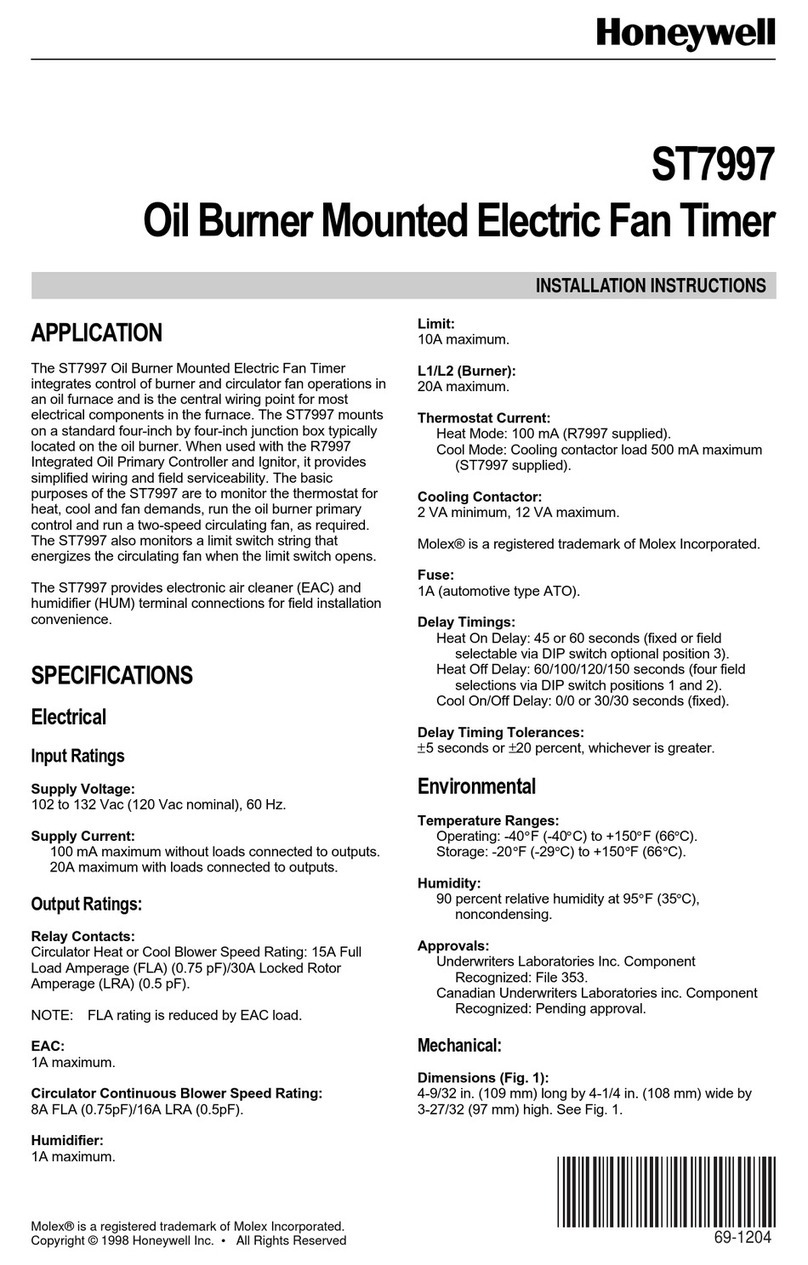
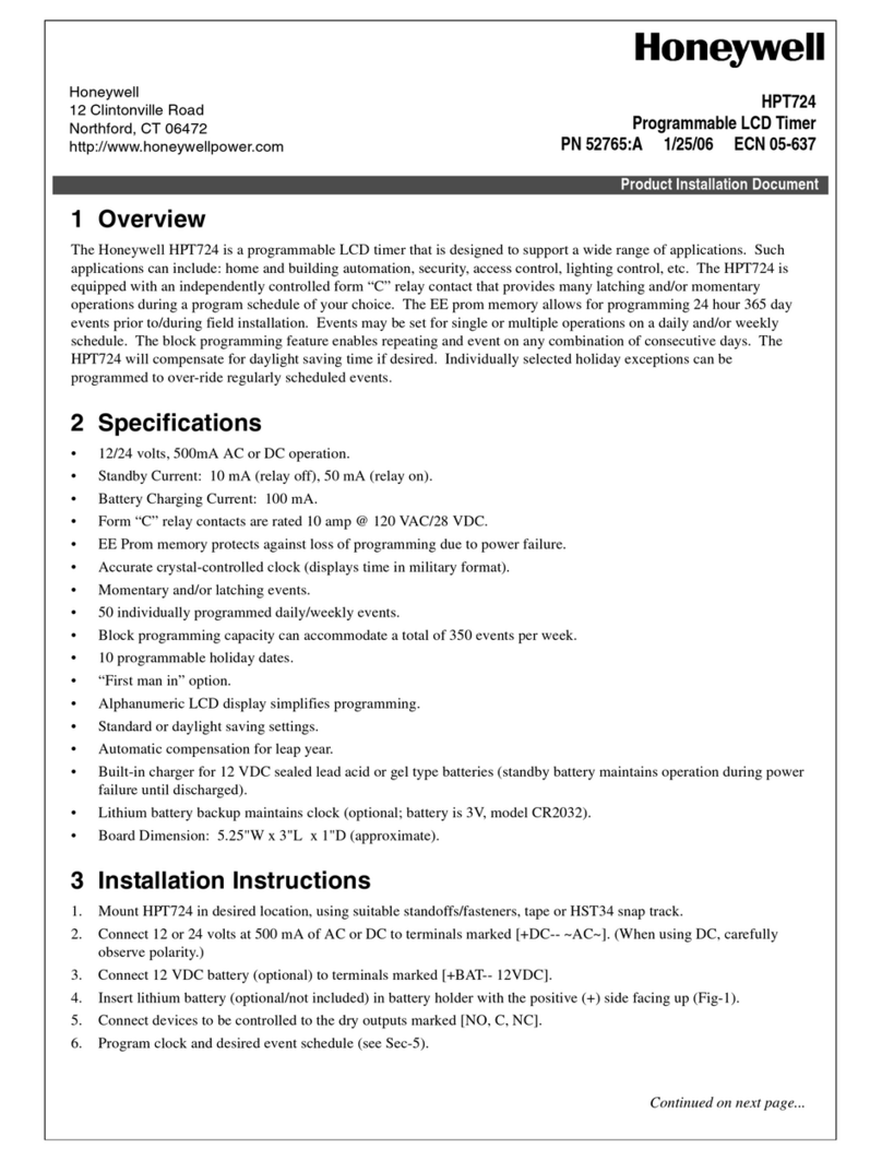
The ST699 is designed for fixed wiring only and must be
Ensure the wiring connections to the mains supply is via a
fuse rated at not more than 3 A and a Class "A" switch
(having contact separation of at least 3 mm in all poles).
Remove the terminal cover to allow access to the wiring
terminals as shown in fig.2. Connect the systems wiring as
shown by the specific applications wiring diagram. A
maximum of two 2.5 mm2(cross sectional area) wires can be
connected to each terminal as shown in fig.3. Each wire
should be stripped of insulation to a length no greater than
7mm to safeguard against the possibility of electrical shorts.
Fig. 2
*A link must be provided between L-5-8 on the subbase of
ST699 for all Sundial Plans, or fully controlled pumped
primary systems
Fig. 3
Basic System 3 - as System 2 except boiler cycling
controlled by room thermostat when DHW is switched
OFF
Systems Wiring
DHW OFF
DHW ON
