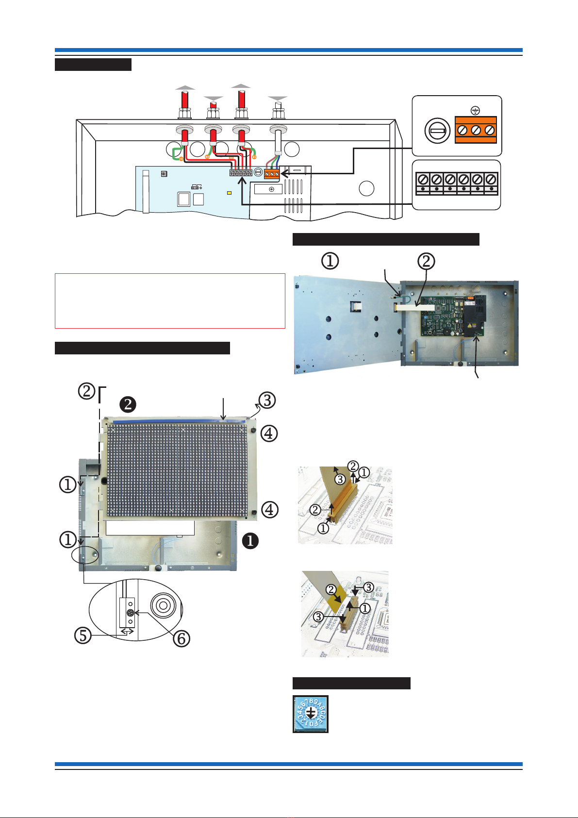
Honeywell Gent Vigilon A3 Mimic Instruction manual

Customised Mimic
Zonal Mimic
A Vigilon A3 Mimic panel (VIG-MIM-A3) must be
connected to a loop circuit of a Vigilon fire detection and
alarm system. It is used to provide indication of fire
events in the system. However it can also be used to
provide indication of fault and supervisory events in the
system. The panel can be mounted in landscape or
portrait orientation.
A Customised Mimic holds a pictorial overlay that
represents the protected building or an area within. A fire
event is indicated by the illumination of appropriate red
LEDs behind the overlay to show the location of the fire.
A Zonal Mimic provides a traditional zone by zone
indication of a fire. Each zone is given a location label to
identify the area within a building.
The panel illumination defaults to a Zonal Mimic but can
be reprogrammed during commissioning to be a
Customised Mimic. An array of red lights illuminates
individually or in groups. Illuminations may be applied to
include custom shapes, text and digital clock in small or
large size. A site specific 'welcome message' may be
configured for display during quiescent conditions that
can scroll if it is too long to fit the display area. First or
last fire flashing option, with in phase or anti phase flash.
The panel has its own mains derived power supply with
battery for standby power in the event of mains supply
failure.
Technical Data
Panel dimensions height 403mm, width 338mm,
depth 101mm
Weight 7.9Kg without batteries
10.5Kg with batteries
Storage temperature -10 to 55ºC
Operating temperature 0 to 45ºC
Relative humidity
(Non condensing)
Up to 90% temperature
5-45°C
Battery 2 x 6V 7Ah sealed lead acid
(weight 1.3Kg each)
The integral battery provides
power for 72 hours in standby
condition and a further
30 minutes in alarm.
Mains operating
voltage
230V 50Hz +10% -6%
Emission BS EN61000-6-3 : 2001
Immunity BS EN50130-4 : 1996 : Part 4
LVD BS EN 60950-2006
Ingress protection IP30 (estimated)
Colour Door - Pantone 422
Back box - Graphite Grey
(RAL 7024)
Control Cancel fault buzzer / lamp test
button
Indicators 1536 high intensity RED LEDs.
Loop connection 3-way connection to a loop
circuit
Maximum number per
loop
(A maximum load
factor of 1000 allowed
per Vigilon loop circuit)
Maximum number of combined
repeat and mimic panels per
loop = 4
load factor per panel = 3
Typical Mimic illuminations
4188-945_issue 2_05/10_pt1_A3 Mimic 1
Data and Installation
Vigilon A3 Mimic panel
VIG-MIM-A3
by Honeywell
Flashing in phase
or anti phase
Customised Mimic Zonal Mimic
ZONE n
Zone in fire
- steady indication
Latest zone in fire
- flashing indication

Compatibility
As a Zonal Mimic panel the system control panel must
have the following card software:
Control panel CARD
EN54
Control Panel
software
BS5839
Control
Panel
software
LPC
New Shorter Card ONLY
³V4.19 ³3.90
³means equal to or greater than
As a Customised Mimic panel the system control panel
must have the latest card software.
Installation
Fuses on Master Repeat Card
Fuses Rating
FS4 3.15A AB Ceramic 20mm x 5mm
FS2 3.15A AB Ceramic 20mm x 5mm
FS3 2A QB 20mm x 5mm
The Mimic Panel set consists of:
Component Quantity
uBackbox assembly
1
vInner door assembly
1
wOuter cover assembly
1
xKey for Outer cover 1
y3.15A 20mm x 5mm AB Ceramic
2
z2A 20mm x 5mm Quick Blow Fuse
1
{Battery lead
1
|Link lead 1
}6V 7Ah Battery
2
~Overlay pack for A3 Mimic panel
1 x pre-printed Zonal sheet
2 x blank A3 sheets for printing
a Mimic or Zonal overlay
1 x LED spacing sheet
The overlays in the pack are high quality UV
protected A3 paper.
Amagnetic strip used to hold an overlay in
place is fitted to the top side of the inner door.
1 Set
Mounting the backbox
The A3 Customised Mimic panel can be mounted either
landscape or portrait, while an A3 Zonal mimic panel must
only be mounted landscape when using the overlay
supplied.
a. Locate the package Back box assembly u.
Landscape orientation
Portrait orientation
b. Knock out the required cable entry points from the
back box.
c. Mark out the 4-back box fixing positions on the wall to
which the panel is to be mounted and secure it with
suitable fixings.
&Ensure the mains power is isolated to
from the panel.
d. Terminate the loop and mains cables at the entry
points and if required connect the cables to the
appropriate terminals.
e. All the other parts are installed during commissioning.
Data and installation A3 Mimic Panel
2 4188-945_issue 2_05/10_pt1_A3 Mimic
byHoneywell
VIGILONFIRE SYSTEM
NOTYET IN SERVICE
AWAITINGCOMMISSIONING
Back box
T
op ca
bl
e entry po
i
nts
5-off Back
5-off Top
Earth points
4-off
380mm
240mm
by Honeywell
VIGILON FIRE SYSTEM
NOT YET IN SERVICE
AWAITING COMMISSIONING
Back box
Earth points
4-off
380mm
240mm
Cable entry points
5-Backand5-Top
by Honeywell
VIGILON FIRE SYSTEM
NOT YET IN SERVICE
AWAITING COMMISSIONING

External wiring
The external cables are routed into the back box using the
cable entry points on the back box. The left 4 entry points
are for the loop cables that connects to terminal block P16.
The right cable entry point is for the mains cable which is
connects to the terminal block P9.
"All the other parts supplied with the A3 mimic
panel are fitted during the commissioning stage, however
the procedures are described here for completeness.
How to fit the inner door assembly
The following procedures describe how to fit the inner
door assembly to the backbox.
Align the inner door assembly vto the two hinge pin
positions jon the back box uand slide the door down
until it is seated correctly. Insert the top (removable) hinge
pin kand secure it by rotating the pin into the back box.
Close the inner door assembly land lock it using the
fastners at position m. For minor adjustment of the inner
door, open the fixing screw and adjust the hinge plate
to a required position and then secure the plate to the
backbox by tightening the screw .
Where to connect the internal cables
Remove the protective cardboard cover from the Master
Repeat Card. Connect the earth lead jfrom the back box
to the inner door assembly. Connect the flat flexible cable
kto socket P13 on the Master Repeat Card , see details
on fitting and remove of flat flexible cable.
How to disconnect a flat flexible cable
Hold the locking tab by the
edges at positions jand
lift it upwards one side at a
time kto disengage the flat
flexible cable. Then remove
the cable lfrom the
socket.
How to connect a flat flexible cable
Hold the locking tab by the
edges and lift it upwards a
little jand insert the flat
flexible cable kinto the
socket. Ensure the cable
contacts are on the opposite
side to the locking tab. Push
down the locking tab lto
lock the cable.
Setting the switch SW3
A Customised Mimic panel or Zonal
Mimic panel requires the switch SW3
located on the Master Repeat Card to
be set to position '0'.
4188-945_issue 2_05/10_pt1_A3 Mimic 3
A3 Mimic Panel Data and installation
Inner door assembly
Hinge pin
Back box
assembly
Magnetic strip
Adjustable Hinge Plates
P9
LN
FS4
3.15A(T)
mains fuse
01 L1 02 L2
0C LC
P16
Loop IN
Loop
O
UT From
Mains fused spur
Loop COM
Master Repeat Card
01 L1 02 L2
0C LC
P9
L
N
N
P17
DANGER
WRITE PROTECT
L N
FS4
P16
P4
RESET
Inner door
Back box
Fit earth lead
from back box
to inner door
Connect the flat
flexible cable from
inner door to MRC
Master Repeat Card (MRC)
P13
Top ri
g
ht of the new MRC
Top ri
g
ht of the new MRC
P13
SW3

Power up
Fit the two battery upright inside the backbox , in the
correct orientation with the + terminal to the left, between
the 'battery stop brackets'. Connect the battery lead {and
link wire |as illustrated in the diagram above. The mains
power to the panel can then be switched ON. Power up
from battery only is possible by pressing switch SW2 on
MRC.
Lamp Test
Press the button located on the bottom centre face of the
panel to conduct a 'lamp test'. The test will illuminate
alternate blocks of LEDs so that they can be checked and
sound the two tone internal buzzer for the test duration.
Zonal Mimic overlay
A landscape Zonal Mimic makes use of the zonal overlay
supplied. An editable PDF file of the zonal overlay is
available on the Gent Expert Forum
(www.gentexpert.co.uk). The file is used for the entry of
zone labels and subsequent printout on to one of the blank
A3 sheets supplied.
Customised Mimic overlay
To create a customised mimic plan use the LED spacing
sheet provided to draw a representation of the protected
building or areas within, such that the layout is drawn
around the LED matrix. The final plan may be drawn using
a CAD package and printed to one of the blank A3 sheets
supplied, to make the customised mimic overlay. To avoid
waste of blank A3 sheets supplied, do a trial print to
normal A3 paper and check the plan for alignment with the
LED matrix.
How fit an overlay
Place the required printed overlay on top of the LEDs and
align the plan such that it fits inside the LED matrix and
hold the overlay in place using the magnetic strip. The
overlay is secured in place when the outer cover is fitted to
the panel.
How to fit the outer cover
Hook the Outer Cover
over the top edge of
the Back Box . Close
the bottom of the Outer
Cover onto the Back box
and secure the Outer
Cover by the two captive
screws on the cover using
the key supplied.
Ensure the zonal mimic
or customised mimic
plan is located centrally
within the anti glare
window of the outer
cover.
Data and Installation A3 Mimic Panel
Gent by Honeywell reserves the right to revise this publication from time to time and make changes to the content hereof without
obligation to notify any person of such revisions of changes.
Hamilton Industrial Park, Waterside Road, Leicester LE5 1TN, UK Website: www.gent.co.uk
Telephone +44 (0) 116 246 2000 Website: www.gentexpert.co.uk Fax (UK): +44 (0)116 246 2300
4 4188-945_issue 2_05/10_pt1_A3 Mimic
by Honeywell
Do not dispose of with your normal household waste.
Do not burn.
WEEE Directive:
At the end of their useful life, the packaging,
product and batteries should be
disposed of via a suitable recycling centre.
At the end of their useful life, the packaging,
product and batteries should be disposed of
via a suitable recycling centre and in
accordance with national or local legislation.
FS2
3.15A(T)
Ceramic
(Anti Surge)
Battery Fuse
BT+ BT-
+
RS485 0V 24V
-
BUZZER
DISABLE
DANGER
DO NOT
REMOVE
P5
FS2
P1
SW3
PB2
WD1
P14
P7
USB
FS3
2A(QB)
DANGER
WARNING
Removal of
cover exposes
live parts.
++
--
2x6V
7Ah Battery
Back box
Master Repeat Card
Inner Door
Black
Red Battery lead
Link lead
BATTERY
POWER UP
SW2
Magnetic Strip
Custom Mimic or Zonal
overlay
Mimic panel
Back box with inner door assembl
y
A
A
Outer Cove
r
Back box
Table of contents
Other Honeywell Touch Panel manuals

Honeywell
Honeywell CENTRA LINE WEB-HMI Series User manual

Honeywell
Honeywell VPX Series User manual

Honeywell
Honeywell OmniAssure User manual

Honeywell
Honeywell SmartLine RMA801 Instruction Manual

Honeywell
Honeywell 012577 Instruction manual

Honeywell
Honeywell SmartLine RMA801 Instruction Manual

Honeywell
Honeywell QXe Recorder User manual

Honeywell
Honeywell Tuxedo Touch Series Assembly instructions

Honeywell
Honeywell S7999B Operation manual

Honeywell
Honeywell Galaxy TouchCenter Plus User manual