manuals.online logo
Brands
  1. Home
  2. •
  3. Brands
  4. •
  5. Honeywell
  6. •
  7. Touch Panel
  8. •
  9. Honeywell OmniAssure User manual

Honeywell OmniAssure User manual

Installation Instructions / OmniAssure Touch Square
OmniAssure Touch Square
P30742-10-0G0-01
2019-05-07
EN Installation Instructions......................................2
This documentation can be downloaded from our websites in English,
German, French, Spanish, Italian, Portuguese, Czech, Polish, Russian,
Turkish and Mandarin.
GLOBAL:
DACH:
www.security.honeywell.com
www.security.honeywell.de
Model name Smart proX Mobile Color Item. no.
X X X Black OT4800BHONG
OmniAssure Touch Square
X X Black OT4700BHONG
X X X Black OT4816BHONG
OmniAssure Touch Square
16 key X X Black OT4716BHONG
X X X White OT4800WHONG
OmniAssure Touch Square
X X White OT4700WHONG
X X X White OT4816WHONG
OmniAssure Touch Square
16 key X X White OT4716WHONG
I
II
III
IV
⑨
⑩
⑪
V
2 Installation Instructions / OmniAssure Touch Square
Subject to change without notice.
1 Scope of delivery
1 Installation instructions
1 Reader front
1 Mounting backplate
5 Wall anchors (5 x 25 mm or #8 x 1”)
5 Screws (panhead, 3 x 30 mm or #4 x 1¼”)
3 Enclosure screws (metric, M2 x 5 mm panhead)
4 Enclosure screw caps
2 General
The OmniAssure Touch Square Reader was tested at the panels:
– NetAXS 123 V6 (Wiegand)
– ProWatch 6k (Wiegand)
– Pro32 (Wiegand)
– Mercury EP1502 (OSDP)
Mobile credentials:
– proX (EM4102)
– MIFARE classic
– MIFARE DESFire EV1/EV2
– OmniAssure OES
– QKey
– HID
– ISO-SNR Quadrakey
– Bluetooth Low Energy
Physical interfaces:
– Wiegand
– RS-485 (OSDP 2.1.7.)
The Reader Utility Application is used to configure:
– credential bit formats and length
3 Installation
All dimensions in drawings are in mm.
NOTE
All wiring shall be in accordance with applicable codes
and regulations. Observe applicable building codes and
safety regulations in determining the reader position.
UL 294: Installation must be done in accordance with
National Electrical Code, ANSI/NFPA 70.
General terms
– The reader base can be used as a drilling template where necessary.
– When positioning the reader base, ensure that the backtamper can
be securely screwed in; otherwise the tamper detection is reduced to
opening monitoring.
– We recommend that the connection cable of the reader is guided
through the reader base from the side with the lettering reading "Hon-
eywell" before fixing the reader base.
– Secure the reader base without exerting excessive force.
– Use the mounting material included in the accessories. If you need
more materials, ensure that these have the same diameter.
–The power supply of the reader must be switched off while the
reader is connected. Risk of damage!
3.1 Important notes on mounting
– Pay attention to the minimum distances (see "V", page 1).
Mounting readers in close proximity of each other will reduce perfor-
mance, the minimum recommended mounting distance side-by-side
or back-to-back is 125 mm (5”).
– Mounting the reader on a metal surface may reduce performance, a
plastic separator of at least 6 mm (¼”) is recommended.
3.1.1 Mounting height
In order to operate the keypad and read the indications optimally, install
the reader at a height of 130 to 140 cm (51 to 55”) above the floor.
3.1.2 Necessary cable reserve
In order for the reader to be able to dismounted when necessary, there
must be a sufficient cable reserve in the direct vicinity of the reader.
Depending on the type of mounting, the cable reserve can be placed in
the flush mounted socket, or in a nearby junction box.
3.1.3 Outdoor use
– If the reader is to be used outdoors, the cable entry must be sealed
on both sides of the wall, to prevent condensation.
– The connector for the connection cable of the reader should be
located indoors.
3.2 Mounting for flush mounted wiring
see "I", page 1
Screw the reader base onto a DIN-style f.m. socket [1] (preferred mount-
ing) or directly onto the wall. For sockets from Switzerland, the reader is
fixed at the corners.
Screw the backtamper [2] onto the wall, so that if the reader is torn off the
wall, the actuator pin [3] remains secured to the wall, thus releasing the
cover contact and signalling a tamper situation.
3.3 Mounting for surface mounted wiring with wall plate
see "II", page 1
Place the wall plate for surface mounting [4] (Item no. LU45BB) between
the reader base [5] and the wall and screw both firmly onto the wall. Then
screw on the tear-off protection (see chapter "Mounting for flush mounted
wiring").
The wall plate can be rotated in 90° steps so that the surface mounted
cable entry [6] can be from at the bottom, at the top, on the left or right.
3.4 Mounting with Visual Cover
see "III", page 1
The visual cover (item no. OT4XBHONG/OT4WHONG) is suitable for
flush wiring and surface wiring.
The mounting is identical to the mounting with the wall plate.
Note that the visual cover cannot be rotated. For this reason, a surface
mounted cable entry [7] is therefore only possible from below or above.
Break [8] if necessary.
For a lateral cable entry, it is therefore necessary to provide the wall plate
under the sight protection.
3.5 Fasten the reader
see "IV", page 1
[9] Hang the reader from above in the reader base.
[10] Snap shut below.
[11] Close with the two attached screws.
After completing the mounting and functional testing seal the housing.
To do this, press the enclosed seals into screw holes.
Installation Instructions / OmniAssure Touch Square 3
3.6 Test the reader / Commissioning
Apply power (the green LED indicates power) and present a valid creden-
tial. The light ring should flash and the sounder should produce a short
tone indicating a successful read. If the Host system is connected the light
ring and sounder should follow the functionality of the Host system.
3.7 Cable specification
– The reader is supplied with 2 m (6 ft.) of shielded, 8-conductor
0,14 mm² (AWG 26) cable which may be extended with the length
and size of cable listed below.
min. conductor size
for panel power suppy
max. cable
length
9,5 V1) 12 V 18 V
Interface
meters feet mm² AWG mm² AWG mm² AWG
61 200 0,55 20 0,33 22 0,22 24
91 300 0,82 18 0,5 20 0,33 22
Wiegand /
RS-485
(cable
power) 152 500 1,35 16 0,81 18 0,54 20
RS-485
(local power) 1220 4000 0,16 mm² / AWG 25
1) to ensure that the reader power supply is at least 7 V DC
3.8 Wire assignments
The connection must be carried out in de-energized state! Risk of
damage!
To ensure reliable functioning, ensure that a possible extension of the 4 m
connecting cable does not exceed 152 m (condition: no external voltage
supply unit is required). For extension purposes up to 152 m an additional
JY(ST)Y (6x2x0.6 mm) cable can be used.
The reader can be used remotely for extension purposes at a distance of
max. 1220 m. We recommend using a Cat 5 connecting cable (condition:
an external voltage supply unit for the reader is required).
In general, by use of RS-485 interface: When the reader is the last user
on the RS-485 bus, a 120 Ω end-of-line resistor (from TRX+ to TRX-)
must be installed in front of the reader. For further information, refer to the
description of the corresponding controller.
InterfaceWire color
Wiegand RS-485
red POWER (+U_b) POWER (+U_b)
black GND (0 V) GND (0 V)
white D1 TRX+
green D0 TRX-
blue Hold line do not connect
yellow Buzzer do not connect
orange LED green do not connect
purple Tamper do not connect
Caution
Floating communication lines may cause spurious emissions, invalidating
certification. Ensure all communication lines are properly biased and ter-
minated.
Input Hold line
This input makes it pos-
sible to switch 2 read-
ers in parallel (e.g. at
NetAXS).
Reader 1
Reader 2
Hold line 2
Hold line 1
NetAXS
GND
Tamper line
Physical tamper switches:
– tear-off
– enclosure
The electronic switch opens when
the operating voltage +U_b fails.
mechanical tamper switch
electronic tamper switch
Tamper line
4 Operation
When a credential is read successfully, the light ring lights briefly, the
sounder sounds a short tone and the credential associated code is sent
to the Host system.
The light ring and sounder are also controllable by the Host system.
Reader output formats are determined by the personalization of the cre-
dential and/or configuration of the reader; on SmartTech and MultiTech
readers the behaviour of the light ring and sounder can be modified
through configuration.
4.1 Short briefing of buttons and LEDs
OmniAssure Touch Square 16 key
A
B
I
E
C
F
D
G
H
K J
A Numeric keypad for PIN entry
(PIN= Personal identification number)
B LED light ring
C, E, G, I Not used
D LED green
F LED yellow
H Duo LED red/green
J Acknowledge: execute the PIN code / Activate
the BLE credential
K Clear PIN code entry
4 Installation Instructions / OmniAssure Touch Square
OmniAssure Touch Square
A
C
B
D
E
A LED light ring
B LED green
C LED yellow
D Duo LED red/green
E Activate the BLE credential by touching the
touch-sensitive surface
4.2 Requirements to credential type and operation
The following notes and information can be found in the product accom-
panying documents of the panels:
– NetAXS 123 V6 (Wiegand)
– ProWatch 6k (Wiegand)
– Pro32 (Wiegand)
– Mercury EP1502 (OSDP)
All credential type, i.e. Bluetooth authentication requirements
including the following:
1. Electronic credential transmission technology Bluetooth and RFID.
Bluetooth and RFID protocol names:
Default Square OES WG38,BLE,HID-Prox,EM-Prox
DF UID WG26
DF UID WG32
DF UID WG37
DF UID WG56
DF UID-L WG26
DF UID-L WG32
DF UID-L WG37
DF UID-L WG56
EM-Prox WG26
EM-Prox WG32
EM-Prox WG34
EM-Prox WG40
HID
MF UID WG26
MF UID WG32
MF+DF UID WG26
MF+DF UID WG32
MF+DF UID WG37
MF+DF UID WG56
MF+DF UID-L WG26
MF+DF UID-L WG32
MF+DF UID-L WG37
MF+DF UID-L WG56
OSDP OmiAssure OES WG38 HID UniKey
OSDP OmiAssure OES WG38
OmniAssure OES WG38
OmniAssure OES WG38 UniKey 38 bit
EM-Prox(+EM4450)WG32
QKey WG34
2. Config App for programming the reader (Reader Utility by HON). Also
the credential bit format and length will be configured by the App dur-
ing the configuration, so find details in description of App. The follow-
ing abbreviations are used in the Config App:
DF DesFire
MF Mifare Classic
UID Serial Number, continuous numbers like Omni-
Assure
UID-L Serial Number, format like LuminAXS,
Omniprox
WGxx Wiegand xx Bit
EM-Prox EM-Marin 125 kHz H4102 + H4450
HID HID 125 kHz
OES WG38 38 Bit Wiegand Diversified Keys, card
ODPEV28N38
BLE Bluetooth UniKey format
QKey WG34 Quadrakey Wiegand 34 Bit
Installation Instructions / OmniAssure Touch Square 5
3. Use the following operating system (OS) and revision level, along with
the credential device application software with following level: Boot-
loader V4.2.xxx / Application 4.2.xxx / OS 4.2.xxx
4. Installer/dealer can access the reader via config app ‘Reader Utility by
Honeywell’ (Google Play store). Verification is required (SITE code).
The access control system uses 3 types of verification for the user:
Available are pin code, physical credential and mobile credential.
– The reading of a physical credential and an electronic device (BLE),
transmitting user data to the reader interface is the same.
– Have a look at the manual of the system for more details like instruc-
tions on how to silence a trouble, functions of all switches/buttons,
description of the conditions that might be expected to result in false
alarms or impaired operation of the product and service information.
5 Classifications
UL 294: Destructive attack level IV, line security level I,
endurance level IV, power level I.
Access Control Feature: Single Point Locking
Device with Key Locks Level I.
EN 60839-11-1: Grade 3, environmental class III
6 Certifications
CE, FCC, UL294
FCC ID: UA2OT4XXXBHON
UA2OT4XXXWHON
Intertek: ETL listed Intertek 5014020
7 FCC Regulations
7.1 Warning (Part 15.21)
Changes or modifications not expressly approved by the party responsible
for compliance could void the user’s authority to operate the equipment.
7.2 Compliance statement
This device complies with part 15 of the FCC Rules and with the Industry
Canada license-exempt RSS standard(s). Operation is subject to the fol-
lowing two conditions:
(1) this device may not cause harmful interference, and
(2) this device must accept any interference received, including interfer-
ence that may cause undesired operation.
7.3 Information to the user (Part 15.105 (b))
Note: This equipment has been tested and found to comply with the limits
for a Class B digital device, pursuant to part 15 of the FCC Rules. These
limits are designed to provide reasonable protection against harmful inter-
ference in a residential installation. This equipment generates, uses and
can radiate radio frequency energy and, if not installed and used in accor-
dance with the instructions, may cause harmful interference to radio com-
munications. However, there is no guarantee that interference will not
occur in a particular installation. If this equipment does cause harmful
interference to radio or television reception, which can be determined by
turning the equipment off and on, the user is encouraged to try to correct
the interference by one or more of the following measures:
– Reorient or relocate the receiving antenna.
– Increase the separation between the equipment and receiver.
– Connect the equipment into an outlet on a circuit different from that to
which the receiver is connected.
– Consult the dealer or an experienced radio/TV technician for help.
8 CE Declaration of conformity
Hereby, the Novar GmbH declares that the radio equip-
ment readers OmniAssure, item no. OT4700BHONG,
OT4716BHONG, OT4800BHONG, OT4816BHONG,
OT4700WHONG, OT4716WHONG, OT4800WHONG
and OT4816BHONG are in compliance with Directive
2014/53/EU.
This symbol on our product shows a crossed-out
"wheelie-bin" as required by law regarding the Waste
of Electrical and Electronic Equipment (WEEE) disposal.
This indicates your responsibility to contribute in saving
the environment by proper disposal of this Waste i.e.
Do not dispose of this product with your other wastes.
To know the right disposal mechanism please check the
applicable law.
The full text of the EU declaration can be downloaded from our homepage
https://www.security.honeywell.de/ in the service/download area.
9 Technical specification
Dimensions 80 x 80 x 22 mm / 3.15 x 3.15 x 0.87 inch
Operating temperature -40 °C to 66 °C / -40 °F to 151 °F
Protection class IP65
Protection class UL/ULC IP4X / IK04 (enclosure)
Environmental class III
Humidity condition max. 93±2% at 32±2 °C / 89.6±3.6 °F
0 - 95% non-condensing
Installation and use Indoor and outdoor usage
Interfaces Wiegand, RS-485
Reading range 0 ... ≈70 mm / 0 ... ≈2,75" (depending on credential)
BLE range 0 ... ≈5 m / 0 ... ≈197"
Power supply reader 7.0 V to 18 V DC (12 V recommended)
mA
Watt at 7 V DC at 12 V DC at 18 V DC
avg peak avg1) peak2) avg1) peak2) avg1) peak2)
Max. Power consumption
Current consumption
1.8 4.0 250 530 150 320 100 220
Used frequency bands
- 119 kHz to 135 kHz
- 13.56 MHz
- 2400 to 2483.5 MHz
Transmitted power
< 10 dBμA/m
< 0 dBμA/m
< 1 mW e.i.r.p.
1) The "average" current is measured in Idle mode (factory setting, light
ring is slightly blue)
2) The "peak" current is measured with card activation (factory setting,
light ring is on)
Honeywell Commercial Security
Novar GmbH
Johannes-Mauthe-Straße 14
D-72458 Albstadt
www.honeywell.com/security/de
P30742-10-0G0-01
2019-05-07
© 2019 Novar GmbH

Other Honeywell Touch Panel manuals

Honeywell 012577 Instruction manual

Honeywell

Honeywell 012577 Instruction manual

Honeywell Gent Vigilon A3 Mimic Instruction manual

Honeywell

Honeywell Gent Vigilon A3 Mimic Instruction manual

Honeywell UDC 2300 User manual

Honeywell

Honeywell UDC 2300 User manual

Honeywell Galaxy TouchCenter Plus User manual

Honeywell

Honeywell Galaxy TouchCenter Plus User manual

Honeywell VPX Series User manual

Honeywell

Honeywell VPX Series User manual

Honeywell S7999B Operation manual

Honeywell

Honeywell S7999B Operation manual

Honeywell SmartLine RMA801 Instruction Manual

Honeywell

Honeywell SmartLine RMA801 Instruction Manual

Honeywell ADEMCO 6271CV User manual

Honeywell

Honeywell ADEMCO 6271CV User manual

Honeywell KI 209 User manual

Honeywell

Honeywell KI 209 User manual

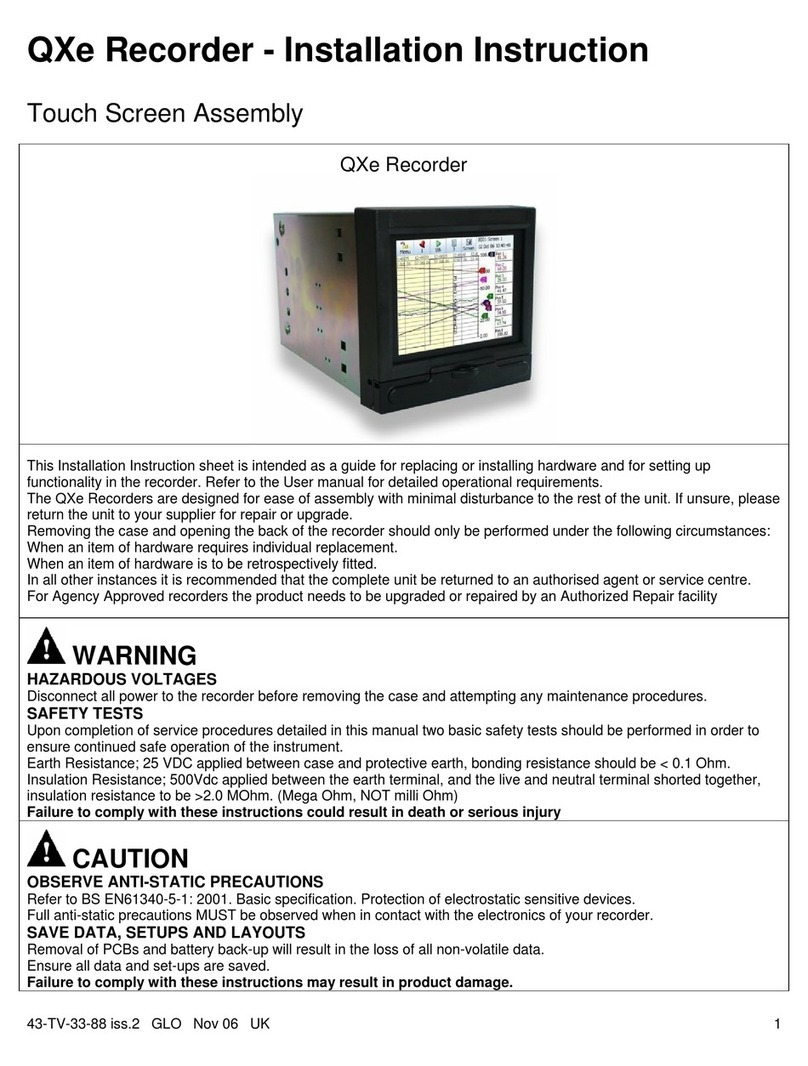
Honeywell QXe Recorder User manual

Honeywell

Honeywell QXe Recorder User manual

Honeywell XS712 User manual

Honeywell

Honeywell XS712 User manual

Honeywell Tuxedo Touch Series Assembly instructions

Honeywell

Honeywell Tuxedo Touch Series Assembly instructions

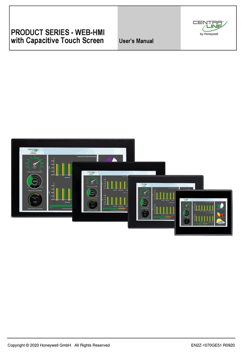
Honeywell CENTRA LINE WEB-HMI Series User manual

Honeywell

Honeywell CENTRA LINE WEB-HMI Series User manual

Honeywell SmartLine RMA801 Instruction Manual

Honeywell

Honeywell SmartLine RMA801 Instruction Manual

Popular Touch Panel manuals by other brands

Acnodes PCM8011 user manual

Acnodes

Acnodes PCM8011 user manual

Lenovo K5923 user manual

Lenovo

Lenovo K5923 user manual

FDI ELI70-CR quick start guide

FDI

FDI ELI70-CR quick start guide

Crestron TSW-570PR Series quick start

Crestron

Crestron TSW-570PR Series quick start

AMX AXM-MLC Dimensional drawing

AMX

AMX AXM-MLC Dimensional drawing

panel PSG3-EP Series user manual

panel

panel PSG3-EP Series user manual

Renkforce 2498315 operating instructions

Renkforce

Renkforce 2498315 operating instructions

IEI Technology IKARPC-W10A user manual

IEI Technology

IEI Technology IKARPC-W10A user manual

Aaeon OMNI-3105-BT user manual

Aaeon

Aaeon OMNI-3105-BT user manual

Beijer Electronics X2 pro 4-B2 installation manual

Beijer Electronics

Beijer Electronics X2 pro 4-B2 installation manual

Moxa Technologies MPC-2190 Series Quick installation guide

Moxa Technologies

Moxa Technologies MPC-2190 Series Quick installation guide

Advantech PPC-155T user manual

Advantech

Advantech PPC-155T user manual

Siemens Desigo Touch Series Installation and commissioning instructions

Siemens

Siemens Desigo Touch Series Installation and commissioning instructions

Elo TouchSystems E-Series Quick installation guide

Elo TouchSystems

Elo TouchSystems E-Series Quick installation guide

ADT GE Concord 4 quick guide

ADT

ADT GE Concord 4 quick guide

D3 IFTD T SERIES user guide

D3

D3 IFTD T SERIES user guide

GVS CHTF-3.5/20.1.2 Series user manual

GVS

GVS CHTF-3.5/20.1.2 Series user manual

Icop PEX-090T-8A user manual

Icop

Icop PEX-090T-8A user manual

manuals.online logo
manuals.online logoBrands
  • About & Mission
  • Contact us
  • Privacy Policy
  • Terms and Conditions

Copyright 2025 Manuals.Online. All Rights Reserved.