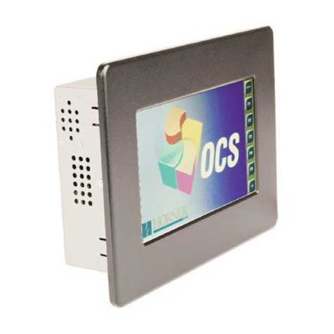
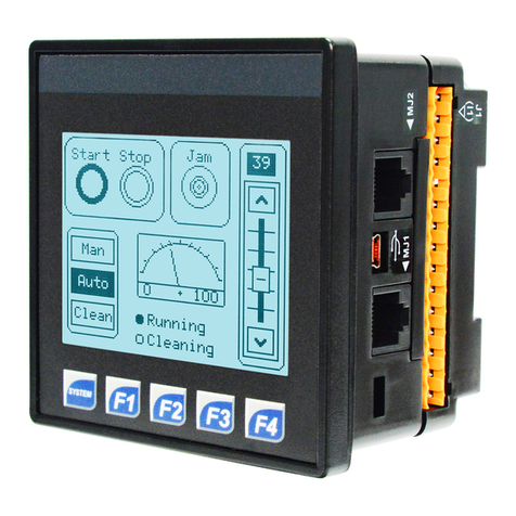
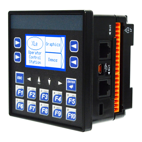
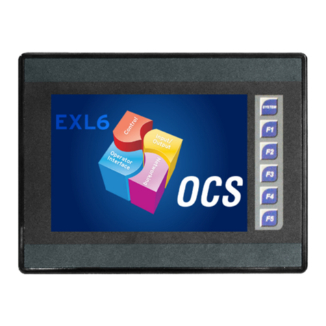
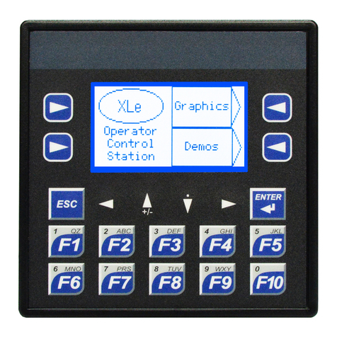
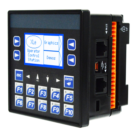
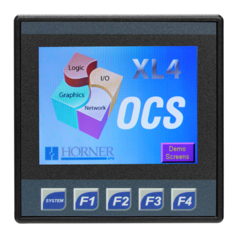
HORNER XL4 6 User manual

Page 1
XL4 - Model 6
12 DC In, 12 DC Out, 17-bit Analog In (mA/V/Tc/mV/RTD), 4 – 12-bit Analog Out
MAN1148-20-EN_XL4_Mod6
Part Numbers
GlobalPartNumber HE-XC1E6
EuropeanPartNumber HEXT251C116
User Manual and Add-Ons
FindthedocumentsviatheDocumentationSearch.
Part # Description
MAN0964 XL4&XL4PrimeUserManual
MAN1142 RechargeableBatteryManual
HE-BAT019 Rechargeable3.6VLithiumBattery
HE-XCK ProgrammingCables
HE-XDAC 2channelAnalogOutputI/Ooptionkit,
selectable0-10V,+/-10V,4-20mA.
HE-XDAC107 4channelAnalogOutputI/Ooptionkit,
selectable0-10V,+/-10V,4-20mA.
HE-XKIT BlankI/OBoard
HE200MJ2TRM Adapter,RJ45(8P8C)maleto8-pos-
itionterminalstrip.
HE-FBD001 Ferritecoreforfilteringoutelectrical
noise.
Battery Maintenance
TheXL4hasanadvancedbatterysystemthatusesa
rechargeablelithiumbattery.Thebatterypowersthereal
timeclockwhenpowerisremoved,anditisneededfor
registerdataretention.ManualMAN0964viatheDocu-
mentationSearchformoredetailsonbatteryreplacement.
Table of Contents
PartNumbers 1
UserManualandAdd-Ons 1
BatteryMaintenance 1
TECHNICAL SPECIFICATIONS 2
GeneralSpecifications 2
ControlandLogic 2
UserInterface 2
Connectivity 2
CONTROLLER OVERVIEW 3
OverviewofOCS 3
PowerWiring 3
Model 6 Specifications 4
DigitalDCInput 4
DigitalDCOutputs 4
AnalogInputs 5
AnalogOutputs 5
WIRING: INPUTS AND OUTPUTS 6
AnalogInputsInformation 6
DigitalInputsInformation 6
ConnectorOverview 7
J1andJ2Wiring 7
J3Wiring 8
J3UniversalWiring&WiringDetails 8
StatusRegisters 9
Registers 9
COMMUNICATIONS 10
SerialCommunication 10
DipSwitches 10
CANCommunications 10
Ethernet 10
DIMENSIONS & INSTALLATION 11
XL4&XL4PrimeDimensions 11
InstallationInformation 11
InstallationProcedure 11
SAFETY & MAINTENANCE 12
Warnings 12
FCCCompliance 12
TechnicalSupport 12
Precautions 12

Page 2
TECHNICAL SPECIFICATIONS
General Specifications
TypicalPowerBacklight
100%
239mA@10V(2.39W)
103mA@24V(2.47W)
PowerBacklightOff 18mA@24VDC(0.43W)
PowerBacklight@50% 24mA@24VDC(0.58W)
RequiredPower
(SteadyState)
189mA@24VDC(4.54W)
426mA@10VDC(4.26W)
RequiredPower(Inrush) 2Afor<1ms@24VDC,DC
switched
HeaterOption* 250mAwithheater*(24VDC)
PrimaryPowerRange 10-30VDC
10-24VDC(withheater*)
RelativeHumidity 5to95%,Non-Condensing
ClockAccuracy
+/-20ppmmaximumat25°C
(+/-1min/month)
RealTimeClock BatteryBacked,
RechargeableLithium
OperatingTemperature -10°Cto+60°C
-40°Cto+60°C(withheater*)
StorageTemperature -20°Cto+60°C
Weight 12oz/340g(withoutI/O)
Altitude Upto2000m
RatedPollutionDegree Degree2Rating
Certifications(UL/CE) NorthAmericaorEurope
*HeaterOption(Model#plus"-22")
Control and Logic
ControlLang.
Support
Register-BasedAdvanced
LadderLogic;
Variable-BasedAdvanced
Ladder
IEC61131-3Languages
LogicProgramSize 2MB,maximum
ScanRate .04ms/kB
DigitalInputs 2048
DigitalOutputs 2048
AnalogInputs 512
AnalogOutputs 512
Gen.Purpose
Registers
50,000(words)Retentive
16,384(bits)Retentive
16,384(bits)Non-retentive
User Interface
DisplayType 3.5”TFTColor
ScreenBrightness 640cd/m2(nits)
Resolution QVGA(320x240)
Color 16-bit(65,535)
User-Program.
Screens
1023maxpages;
1023objectsperpage
Backlight LED-50,000hourlife
BrightnessControl 0-100%viaSystemRegister
%SR57
NumberofKeys 5
Connectivity
SerialPorts 1RS-232and1RS-485on
singularModularJack
USBmini-B USB2.0(480MHz)
Programming&DataAccess
USBA(500mAmax) USB2.0(480MHz)forUSB
flashdrives(2TB)
CANPort
Isolated1kV
RemoteI/O,Peer-to-peer
Comms,Cscape
CANProtocols CsCAN,CANopen,DeviceNet,
J1939
Ethernet 10/100Mb(Auto-MDX)
EthernetProtocols TCP/IP,ModbusTCP,FTP,
SMTP,EGD,ICMP,ASCII
RemoteI/O SmartRail,SmartStix,
SmartBlock,SmartMod
RemovableMemory
microSD,SDHC,SDXCIN
FAT32format,supportfor32GB
max.ApplicationUpdates,
Datalogging


Page 3
CONTROLLER OVERVIEW
Overview of OCS
1. Touchscreen
2. FunctionKeys
3. HighCapacitymicroSDSlot
4. ConfigurationSwitches
5. USBMini-BPort
6. Wide-RangeDCPower
7. CANPort
8. EthernetLANPort
9. USBAPort
10. RS232/RS485SerialPort
NOTE:See"Precautions"onpage12aboutUSBand
grounding.
Power Wiring
NOTE:ThePrimaryPowerRangeis10VDCto30VDC.
Primary Power Port Pins
PIN Signal Description
1Ground FrameGround
2DC- InputPowerSupplyGround
3DC+ InputPowerSupplyVoltage
DC Input / Frame
lSolid/StrandedWire:12-24awg(2.5-0.2mm)
lStriplength:0.28”(7mm)
lTorque,TerminalHold-DownScrews:4.5–7in-lbs
(0.50–0.78N-m)
lDC-isinternallyconnectedtoI/OV-,butisisolated
fromCANV-.AClass2powersupplymustbeused.
Power Up
1. Optional:Attachferritecorewithaminimumoftwo
turnsoftheDC+andDC-signalsfromtheDCsupply
thatispoweringthecontrollers.Seepage1.
2. Connecttoearthground.
3. Applyrecommendedpower.

Page 4
Model 6 Specifications
Digital DC Input
InputsperModule 12Including4ConfigurableHSCInputs
CommonsperModule 1
InputVoltageRange 12VDC/24VDC
AbsoluteMax.Voltage 30VDCMax.
InputImpedance 10kΩ
InputCurrent PositiveLogic NegativeLogic
UpperThreshold
LowerThreshold
0.8mA
0.3mA
-1.6mA
-2.1mA
Max.UpperThreshold 8VDC
Min.LowerThreshold 3VDC
OFFtoONResponse 1ms
ONtoOFFResponse 1ms
GalvanicIsolation None
LogicPolarity SelectableinCscape
I/OIndication 9(IN9-12)
ConnectorType 3.5mmPluggableCageClampConnector
HighSpeedCounterMaxFreq 1MHz
Digital DC Outputs
OutputsperModule 16Including2ConfigurablePWMOutputs
CommonsperModule 1
OutputType Sourcing/10kΩPull-Down
OutputFrequency 500kHz
AbsoluteMax.Voltage 28VDCMax.
OutputProtection ShortCircuit
Max.OutputCurrent/Point 0.5A
Max.TotalCurrent 4AContinuous
Max.OutputSupplyVoltage 30VDC
Min.OutputSupplyVoltage 10VDC
Max.VoltageDropatRatedCurrent 0.25VDC
Max.InrushCurrent 650mAperChannel
Min.Load None
OFFtoONResponse 1ms
ONtoOFFResponse 1ms
OutputCharacteristics CurrentSourcing(Pos.Logic)
PWMOut ≈5kHz
RiseTime 50-115μs
FallTime 8-20μs

Page 5
Analog Inputs
NumberofChannels 6
InputRanges(Selectable)
0-20mA;4-20mADC;0-60mV;0-10VDC;
T/C (Ungrounded):J,K,N,T,E,R,S,B
RTD:PT100,PT1000
%AIFullScale 10V,20MA,100mV:32,000countsfullscale
RTD/T/C:20counts/°C
NominalResolution 17Bits
AbsoluteMax.InputVoltage -0.5to-12VDC(+/-30VDC)
InputImpedance
(Clamped@-0.5to10.23VDC)
T/C/RTD/mV>2MΩ
mA:15Ω+1.5V/V:1.1MΩ
MaxOverCurrent 35mA
GalvanicIsolation None
ConversionSpeed Min.AllChannelsConvertedinapp.<250msor41msperchannelenable
SensorRange
andAccuracy
Input Type: Range: Accuracy:
TCJ(Ungrounded) -120to1000°C/-184to1832°F +/-0.2%offullscale+/-1°C
TCK(Ungrounded) -130to1372°C/-202to2501.6°F +/-0.2%offullscale+/-1°C
TCT(Ungrounded) -130to400°C/-202to752°F +/-0.2%offullscale+/-1°C
TCE(Ungrounded) -130to780°C/-202to1436°F +/-0.2%offullscale+/-1°C
TCN(Ungrounded) -130to1300°C/-202to2372°F +/-0.2%offullscale+/-1°C
TCR,S(Ungrounded) 20to1768°C/68to3214.4°F +/-0.2%offullscale+/-3°C
TCB(Ungrounded)
500to1820°C/212to3308°F
Functionsbelow500°C
withreducedaccuracy.
+/-0.2%offullscale+/-3°C
PT100/1000 -200to850°C/-328to1562°F +/-0.15%offullscale
0-20mA 0-20mA +/-0.15%offullscale
0-60mV 0-60mV +/-0.15%offullscale
0-10V 0-10V +/-0.15%offullscale
Analog Outputs
NumberofChannels 4
OutputRanges 0-10VDC,0-20mA,4-20mA
NominalResolution 12Bits
Max.Errorat25°C(ExcludingZero) 0-20mA0.1%offullscale
0-10V0.1%offullscale
MaximumLoopVoltage 27V
ResponseTime OneUpdateperprogramlogicscan
MinimumResistanceLoad 400Ω
ConversionSpeed Min.AllChannelsOnceperScan
GalvanicIsolation None
TemperatureDriftError 20mA.......0.000143%/°C
0-10V.....0.000151%/°C

Page 6
WIRING: INPUTS AND OUTPUTS
Analog Inputs Information
Rawinputvaluesforchannels1-4arefoundintheregistersasInteger-typedatawitharangefrom0–32000.
AnaloginputsmaybefiltereddigitallywiththeFilterConstantfoundintheCscapeHardwareConfigurationforAnalog
Inputs.Validfiltervaluesare0-7andactaccordingtothefollowingchart:
Data Values
Input Mode: Data Format, 12-bit INT:
0-20mA,4-20mA 0-32000
0-41V 0-32000
T/C&RTD °Cor°FmaybeselectedintheHardwareConfigurationsectioninCscape.Therawvalueisaninteger,
sotheusershoulddivideby10.
Digital Inputs Information
DigitalinputsmaybewiredineitheraPositiveLogicorNegativeLogicfashionasshown.ThesettingintheCscape
HardwareConfigurationfortheDigitalInputsmustmatchthewiringusedinorderforthecorrectinputstatestobe
registered.Whenusedasanormalinputandnotforhighspeedfunctions,thestateoftheinputisreflectedinregisters
%I1–%I12.DigitalinputsmayalternatelybespecifiedforusewithHighSpeedCounterfunctions,alsofoundinthe
HardwareConfigurationforDigitalInputs.RefertotheUserManualviatheDocumentationSearchformoredetails.

Page 7
Connector Overview
Foreaseofoperability,thehighdensityterminalsaredividedintomoremanageablepairsofconnectors(J1A+J1B,
J2A+J2B,J3A+J3B).Toensureproperinstallation,connectorsymbolsmustmatch.
J1 and J2 Wiring
J1 Wiring J2 Wiring

Page 8
J3 Wiring
NOTE:*BothmA&Voutputsareactiveforeachoutputchannel,however,onlytheconfiguredoutputtypeiscalibrated
(maximum4channelssimultaneously).
J3 Universal Wiring & Wiring Details
Wiring Details
Solid/Stranded Wire:12-24awg(2.5-0.2mm2).
Strip Length:0.28”(7mm).
Torque, Terminal Hold-Down Screws:4.5–7in-lbs
(0.50–0.78N-m).

Page 9
Status Registers
Selectable
Range Description
%Rx* Bit-wisestatusregisterenable:Set%Rx.1-%Rx.9hightoenableforregisters%R(x+1)to%R
(x+9).
%R(x+1) Firmwareversion
%R(x+2) Watchdogcount-clearedonpower-up.
%R(x+3) StatusBits: 16...4 3 2 1
Reserved Normal Config Calibration
%R(x+4) Scanrateofthe106board(average)inunitsof100μs.
%R(x+5) Scanrateofthe106board(max)inunitsof100μs.
%R(x+6)
Channel Status: Channel 2 Channel 1
8 7 6 5 4 3 2 1
Open
RTD
Outof
Limits
Shorted
RTD
Open
Sensor OpenRTD Outof
Limits
Shorted
RTD
Open
Sensor
%R(x+7)
Channel Status: Channel 4 Channel 3
8 7 6 5 4 3 2 1
Open
RTD
Outof
Limits
Shorted
RTD
Open
Sensor OpenRTD Outof
Limits
Shorted
RTD
Open
Sensor
%R(x+8)
Channel Status: Channel 6 Channel 5
8 7 6 5 4 3 2 1
Open
RTD
Outof
Limits
Shorted
RTD
Open
Sensor OpenRTD Outof
Limits
Shorted
RTD
Open
Sensor
%R(x+9...14) Reserved
*Example:%Rx=%R500,%R(x+1)=%R501,%R(x+2)=%R502,...
Registers
TheI/OismappedintoOCSRegisterspace,inthreeseparateareas:Digital/AnalogI/O,High-SpeedCounterI/O,and
High-SpeedOutputI/O.Digital/AnalogI/Olocationisfixedstartingat1,butthehigh-speedcounterandhigh-speedout-
putreferencesmaybemappedtoanyopenregisterlocation.
Digital and Analog I/O Functions Registers
Digital Inputs %I1-12
Reserved %I13-31
ESCP Alarm %I32
Digital Outputs %Q1-12
Reserved %Q13-24
Analog Inputs %AI33-38
Reserved %AI1-32
Analog Outputs %AQ9-12
Reserved %AQ1-8

Page 10
COMMUNICATIONS
Serial Communication
MJ1/2 Serial Ports
2SerialPortson1ModuleJack(8posn)
MJ1:RS-232w/FullHandshaking
MJ2:RS-485Half-Duplex
MJ1 PINS MJ2 PINS
PIN SIGNAL DIRECTION SIGNAL DIRECTION
8TXD OUT -- --
7RXD IN -- --
60V GROUND 0V GROUND
5+5V@
60mA OUT +5V@
60mA OUT
4RTS OUT -- --
3CTS IN -- --
2-- -- RX-/TX- IN/OUT
1-- -- RX+/
TX+ IN/OUT
NOTE:AttachoptionalFerriteCore(HE-FBD001)witha
minimumoftwoturnsofserialcable.
Dip Switches
DIP Switches
PIN NAME FUNCTION DEFAULT
1RS-485
Termination
ON=
Terminated OFF
2Spare AlwaysOFF OFF
3FactoryUse AlwaysOFF OFF
TheDIPswitchesareusedtoprovideabuilt-intermination
totheMJ2portifneeded.Theterminationfortheseports
shouldonlybeusedifthisdeviceislocatedateitherendof
themultidrop/daisy-chainedRS-485network.
CAN Communications
CAN Pin Assignments
PIN SIGNAL DESCRIPTION
1V- CANGround–Black
2CN_L CANDataLow–Blue
3SHLD ShieldGround–None
4CN_H CANDataHigh–White
5V+(NC) NoConnect–Red
lSolid/Stranded Wire:12-24awg(2.5-0.2mm).
lStrip Length:0.28”(7mm).
lLockingspring-clamp,two-terminatorspercon-
ductor.
lTorque, Terminal Hold-Down Screws:4.5–7in-
lbs(0.50–0.78N-m).
lV+pinisnotinternallyconnected,theSHLDpinis
connectedtoEarthgroundviaa1MΩresistorand10
nFcapacitor.
Ethernet
Green LED indicates link-whenillu-
minated,datacommunicationisavailable.
Yellow LED indicates activity-when
flashing,dataisintransmission.

Page 11
DIMENSIONS & INSTALLATION
XL4 & XL4 Prime Dimensions
*+/-0.1mmcutouttolerance
Installation Information
lTheXL4/XL4Primeutilizesaclipinstallationmethod
toensurearobustandwatertightsealtotheenclos-
ure.Pleasefollowthestepsbelowfortheproper
installationandoperationoftheunit.
lThisequipmentissuitableforClassI,Division2,
GroupsA,B,CandDornon-hazardouslocations
only.
lDigitaloutputsshallbesuppliedfromthesame
sourceastheoperatorcontrolstation.
lJumpersonconnectorJP1shallnotberemovedor
replacedwhilethecircuitisliveunlesstheareais
knowntobefreeofignitableconcentrationsofflam-
mablegasesorvapors.
Installation Procedure
1. Carefullylocateanappropriateplacetomountthe
OCSBesuretoleaveenoughroomatthetopofthe
unitforinsertionandremovalofthemicroSD™card.
2. Carefullycutthehostpanelperthediagram,cre-
atinga92mmx92mm+/-0.1mmopeningintowhich
theOCSmaybeinstalled.Iftheopeningistoolarge,
watermayleakintotheenclosure,potentiallydam-
agingtheunit.Iftheopeningistoosmall,theOCS
maynotfitthroughtheholewithoutdamage.
3. Removeanyburrsandorsharpedgesandensure
thepanelisnotwarpedinthecuttingprocess.
4. RemoveallRemovableTerminalsfromtheOCS.
InserttheOCSthroughthepanelcutout(fromthe
front).Thegasketmustbebetweenthehostpanel
andtheOCS.
5. Installandtightenthefourmountingclips(provided
inthebox)untilthegasketformsatightseal.NOTE:
Maxtorqueis0.8to1.13Nm,7to10in-lbs.
6. ReinstalltheI/ORemovableTerminalBlocks.Con-
nectcommunicationscablestotheserialport,USB
ports,Ethernetport,andCANportasrequired.

Page 12
SAFETY & MAINTENANCE
Warnings
1. Toavoidtheriskofelectricshockorburns,alwayscon-
nectthesafety(orearth)groundbeforemakinganyother
connections.
2. Toreducetheriskoffire,electricalshock,orphysical
injury,itisstronglyrecommendedtofusethevoltage
measurementinputs.Besuretolocatefusesascloseto
thesourceaspossible.
3. Replacefusewiththesametypeandratingtoprovidepro-
tectionagainstriskoffireandshockhazards.
4. Intheeventofrepeatedfailure,doNOTreplacethefuse
againasrepeatedfailureindicatesadefectivecondition
thatwillNOTclearbyreplacingthefuse.
5. Onlyqualifiedelectricalpersonnelfamiliarwiththecon-
structionandoperationofthisequipmentandthehazards
involvedshouldinstall,adjust,operate,orservicethis
equipment.
6. Readandunderstandthismanualandotherapplicable
manualsintheirentiretybeforeproceeding.Failureto
observethisprecautioncouldresultinseverebodilyinjury
orlossoflife.
7. WARNING-Batterymayexplodeifmistreated.Donot
recharge,disassemble,ordisposeofinfire.
8. WARNING - EXPLOSION HAZARD-Batteriesmustonly
bechangedinanareaknowntobenon-hazardous.
FCC Compliance
ThisdevicecomplieswithPart15oftheFCCRules.Operationis
subjecttothefollowing
twoconditions:
1. Thisdevicemaynotcauseharmfulinterference.
2. Thisdevicemustacceptanyinterferencereceived,includ-
inginterferencethatmaycauseundesiredoperation.
Technical Support
North America
1(317)916-4274
(877)665-5666
www.hornerautomation.com
Europe
+353(21)4321-266
www.hornerautomation.eu
Precautions
Allapplicablecodesandstandardsneedtobefollowedinthe
installationofthisproduct.Adheretothefollowingsafetypre-
cautionswheneveranytypeofconnectionismadetothemodule:
1. Connectthesafety(earth)groundonthepowerconnector
firstbeforemakingany
2. otherconnections.
3. Whenconnectingtotheelectriccircuitsorpulse-initiating
equipment,opentheir
4. relatedbreakers.
5. DoNOTmakeconnectiontolivepowerlines.
6. Makeconnectionstothemodulefirst;thenconnecttothe
circuittobemonitored.
7. Routepowerwiresinasafemannerinaccordancewith
goodpracticeandlocalcodes.
8. Wearproperpersonalprotectiveequipmentincluding
safetyglassesandinsulatedgloveswhenmakingcon-
nectionstopowercircuits.
9. Ensurehands,shoes,andflooraredrybeforemakingany
connectiontoapowerline.
10. MakesuretheunitisturnedOFFbeforemakingcon-
nectiontoterminals.
11. Makesureallcircuitsarede-energizedbeforemakingcon-
nections.
12. Beforeeachuse,inspectallcablesforbreaksorcracksin
theinsulation.Replace
13. immediatelyifdefective.
14. UsecopperconductorsinFieldWiringonly,60/75˚C.
15. UsecautionwhenconnectingcontrollerstoPCsviaserial
orUSB.PCs,especiallylaptops,mayuse“floatingpower
supplies”thatareungrounded.Thiscouldcauseadam-
agingvoltagepotentialbetweenthelaptopandcontroller.
Ensurethecontrollerandlaptoparegroundedformax-
imumprotection.ConsiderusingaUSBisolatordueto
voltagepotentialdifferencesasapreventativemeasure.
This manual suits for next models
2
Table of contents
Other HORNER Controllers manuals

HORNER
HORNER XLE Series User manual

HORNER
HORNER X7 OCS User manual

HORNER
HORNER XL6 Prime Instruction Manual

HORNER
HORNER HE-X10 User manual

HORNER
HORNER XL6 Series User manual

HORNER
HORNER HE-XPC1E3 User manual

HORNER
HORNER XLE Use and care manual

HORNER
HORNER ZX Series User manual

HORNER
HORNER X Series User manual

HORNER
HORNER HE-EXL1E0 User manual