HP 6296A Service manual

•
•
•
DC PowerSupply
HPModel 6296A
Operating and Service Manual

tlf
~
.
~\
0
.....-------F//#1
HEWLETT
____
_
~~PACKARD
OPERATING
AND
SERVICE
MANUAL
DC
POWER
SUPPLY
HP
MODEL
6296A
HP
Part No.
06296-90001
SERIAL NUMBER PREFIX
60
ONE
YEAR
WARRANTY I
This
HP
product
has
aone
year
warranty.
P!eue
rept.:e
the
first
paragraph
of
the
warranty et.atement
on
the
inside
front
COYer
with.
the
following:
Thia
Hewlett·Pacbrd
hardware
product
is
warranted
against deftds
in
mataial
GUI
worlananship
for a
period
of
one
year
from
date
of
delivl'ry.
HP
software
ud
firmware
products,
which
are
designated
by
HP
for
me
with a hudware product
and
when
property
installed
on
that
hardware
product.
are
Waftaftted
not
to
fail
to
execute
theirprogramming
instruc:tiDN
due
to
defects
in
a\aterial and
worknwWtip
for
a period
of
90
days from
date
of
delivery.
If
HP receives notice
of
such
defects
duringthe
wmanty
period,
HP
shall
ftPair
or
repi.:e
software meda
and
firmware
which
do
notexecvte
theirprogrmnming
iN1nlCtioM
due
to
such
defeds. HP does not warrant
that
the
operation
for
the software,
finnw.mre
or hardware lhall
be
uninterrupted
or
mor
free.
CALL
CENTER
LIBRARY
11110
llH
~~11111111111111111111111/U
11111
ml
111111~
2400013351
I
QTS U
BR
/\ fW
Printed
: December,
1961

CERTIFICATION
Hewlett-Packard Company certifies
that
this
product
met its publishedspecffications
at
time
of
shipmentfrom
the
factory.
Hewlett-Packard further certifies
that
its calibration measurements
are
traceable to the United States National Bureau
1af
Standards, to the extent
allowed
by
the Bureau's calibration facility,
and
to the calibration facilities
of
other International
Standards Organization members.
WARRANTY
This Hewlett-Packard hardware product
is
warranted against defects in material and workmanship
for
a period of one
ve•ar
from date of delivery. HP software and firmware products,
which
are
designated by HP
for
use
with
a hardware produ'ct
and when properly installed
on
that
hardware product, are warranted
not
to
fail
to
execute their programming instructions
due
to
defects in material and workmanship
for
a period
of
90 days from date
of
delivery. During the warranty period, HP
Company will, at its option, either repair
or
replace products
which
prove
to
be defective.
HP
does not warrant that the
operation
of
the software, firmware, or hardware shall be uninterrupted or error free.
For warranty service,
with
the
exception
of
warranty options,
this
product must be returned to a service facility designated
by
HP. Customershall prepay shipping charges
by
(andshall payall dutyand taxes)
for
products returned
to
HP
for
warran1ty
service. Except
for
products returned
to
Customer from another country, HP shall pay
for
return
of
products
to
Customer.
Warrantyservices outside the
country
of
initial purchase are included in HP'sproduct price only
if
Customer
pays
HP
interna-
tional prices (defined as destination local currency price,
or
U.S.
or
Geneva Expon price>.
If
HP
is
unable, within a reasonable time,
to
repair
or
replace
any
product
to
a condition as warranted, the Customer shall
be entitled to a refund
of
the purchase price upon return
of
the
product
to
HP.
LIMITATION
OF
WARRANTY
The foregoing warranty shall
not
apply
to
defects resulting
from
improper
or
inadequate maintenance by the Customer,
Customer-supplied software
or
interfacing, unauthorized modification
or
misuse, operation outside
of
the environmental
specifications
for
the product,
or
improper site preparation and maintenance. NO OTHER WARRANTY IS
EXPRESSED
OR
IMPLIED.
HP
SPECIFCALLY DISCLAIMS THE IMPLIED WARRANTIES
OF
MERCHANTABILITY AND
FITNESS
FOR
.A
PARTICULAR PURPOSE.
EXCLUSIVE REMEDIES
THE REMEDIES PROVIDED HEREIN
ARE
THE CUSTOMER'S SOLE
AND
EXLCUSIVE REMEDIES.
HP
SHALL NOT
BE
LIABLE
FOR
ANY
DIRECT, INDIRECT, SPECIAL, INCIDENTAL,
OR
CONSEQUENTIAL DAMAGES,
WHETHER
BASED
ON CONTRACT, TORT,
OR
ANY
OTHER
LEGAL THEORY.
ASSISTANCE
The
abovestatements apply
only
to
thestandardproductwarranty. Warranty options, extendedsupportcontracts, produ1:t
maintenance
agreement$
and
customer
a$$i$tance
11g1eement$
are
also
Bvai/able.
Contact
your
nearest
Hewlett-Packard
Sales
and
Service office
for
further information
on
HP's
fuU
line
of
Support Programs. · ·
•
•
•

•
•
•
MANUAL
CHANGES
Model
6296A
DC
Power
Supply ·
·
Manual
HP
Part
No.
06296-90001
Change
Date
10/03/90
Make
all
corrections in the
manual
according
to
errata
below, then
check
the following
table
for
your
power
supply
serial
number
and
enter
any
listed
change(s) in the
manual.
SERIAL
MAKE
:----------•-------------:
CHANGES
: Prefix
Number
I
I
·---------- -------------·---------
ALL
-----
---
ERRATA
60
00231-00260
1
60
00261-00290
1,2
70
00291-00320
1,2,3
70
00321-00350
1-4
7M
00351-00380
1-5
7M
00381-00410
1-6
7H
00411-00522
1-7
7M
00523-00612
1-8
7M
00613-00712
1-9
7H
00713-01776
1-10
1140A
01777-01796
1-11
1140A
01797-01816
1-12
1140A
01817-02411
1-13
1551A
02412-02419
1-14
1552A
02420-02776
1-15
1730A
02777-02956
1-16
1807A
02957-02986
1-17
1816A
02987-03146
1-18
1834A
03147-03386
I
1-19
1918A
03387-03545
1-20
1929A
03547-04086
1-21
2114A
04087-04246
1-22,•23
2133A
04247-04486
1-23
2234A
I
04487-04926
1-24
2410A
04927-05566
1-25
2631A
05567-05916
1-26
2841A
05917-06036
1-27
2933A
06037-06146
1-28
3003A
06147-06206
1-29
3024A
06207-up
1-27,29,
30
----------------------------------
I
I
I
I
I
I
I
1
ERRATA
In
Table
1-1
(and
paragraph 5-20),
change
the
INTERNAL
IMPEDANCE
AS
A
CONSTANT
VOLTAGE
SOURCE
(Output
Impedance)
specification
to
read:
"OUTPl1l'
IMPEDANCE
{TYPICAL):
Approximated
by
a 5 milliohm resistance in
series
with a 1 microhenry inductance.
On
page
3-2, Figure 3-4, disconnect
strap
between
terminals
A4
and
A5.
and
connect
A5
to
+S.
On
page
3-3, Figure 3-6, disconnect
strap
between
terminals
A7
and
AS
and
con-
nect
A8
+S.
Add
the following note
to
paragraph
3-18
on
page
3-2
and
to
paragraph
4-41
on
page
4-7:
"A
protection
circuit
which
protects the
series
regulator
from
overload
damage
is
ac-
tivated whenever: (1)
a.
short
is
placed
across the supply, or (2) the output
is
rapidly
down
progranmed
by
an
increment
of
more
than 4
to
10
volts.
When
activated,
the protection
circuit
limits
the supply's
output current to about
101
of
rating for a
period of
from
0.5
to
10
seconds depending
on
the
model
and
the load conditions."
On
page
5-6, paragraph 5-22,
change
steps a
and
f as follows:
a.
Connect
test
setup
shown
in Figure 5-4
with switch
51
closed.
f.
Insert
load
resistor
(Ry)
by
opening
switch
S1.
Also,
add
the following note:
"The
short
circuit
protection
circuit
in
this
supply
will
be
activated
if
switch
: S1
is
closed instead of
opened
during
·
this
test."
On
page
5-8,
in
Step 3 of Table 5-4,
change
the
text
to
read:
"If
it
1s not, proceed
to
Step 4."

Page
2 -
HP
P/N
06296-90001 changes -continued
ERRATA
In
the
parts
list
on page
6-5:
Change
C501
to
HP
P/N
0160-0710.
Change
C200
to
fxd
film
.01
uF, 200
V,
HP
P/N
0160-0161.
Change
the
listing
for
Q702,
800,
850, 852,
853
to
2N2907A,
Sprague
56289,
HP
P/I
1853
-0099.·
.change
the
part
number
for
C803
to
0180-1986
and
its
voltage
rating
to
85
V
•
.
Add
pilot
light
DSl
HP
P/N
1450-0566.
Change
SCR
CR502
and
CR504
from
HP
P/N
1884-
0019
to
P/N
1884-0347.
en
,Page 6-T:
Add
R865,
var
ww
250
ohm,
HP
P/N
2100-0439.
Also
add
Spacer-round,
HP
P/N 0380-1551
and
Internal-external
lockwasher,
BP
P/H
2190-0576.
Delete
the
two
types
of
binding
posts
list
and
add
the
following:
black
binding
post,
HP
P/N 1510-0114,
qty.
2
red
binding
post,
HP
P/N
1510-0115.
Add:
Insulator
(CR502,
504),
.HP
P/H 5020
-5595.
For
all
instruments
delivered
on
or
after
July
1,
1978, change
the
HP
P/N
for
fuseholder
from 1400-0084
to
fuseholder
body
2110-0564 and fuseh.o1der
carrier
2110-0565.
On
page
6-7:
Change
the
HP
P/N
for
fuseholder
nut
from
2950-0038
to
2110-0569.
If'
old
fuseholder
must be
replaced
for
any
reason,
replace
complete
·
fuseholder
and
nut
with
new
fusebolder
parts.
Do
not
replace
new
parts
with
old
parts.
On
page
6-8,
note
that
effective
January
1.
1971,
Options 007
(10-turn
voltage
control)
and
008
(10-turn
current
control)
are
.
no
longer
available
individually,
but
are
still
available
combined
as
Option
009. Likewise
Options
013
(10-turn
voltage
control
with
decadial)
are
· no
longer
available
in-
dividually,
but
are
available
combined
into
a
single
new
option
designated
Option
015.
Make
these
changes
wherever
Option
007
•.
008,
013,
or
014
is
mentioned
in
the
manual.
2
ERRATA
On
the
schematic
diagram,
indicate
tbat
t.
nominal
value
for
R313
is
1
k.
ThE!
exa
·value
for
R313
is
factory
selected
to
op-
timize
the
range
of
transient
adj\l.st
pot
R307.
In
Appendix
A,
change
Figure
A-1
Overvoltage
Protection
Crowbar
to
appear
as
shown
below:
DC
POWEii
Sll'Pl.Y
62-...
•
•

' Page 3
·-HP
P/N.06296-90001 changes -continued
CHANGE
·1
Jaif:..
page 6-5, change
C500
from
10,000
uF
to
~,000
uF,
HP
P/N
0180-1929. ·
CHANGE
2
On
the
component
location
drawing (schematic
apron)
make
the following changes:
a.
Interchange
collector
(C)
and
emitter
(E)
designations
for
transistor
Q853
on
the lower
right
hand
side
of drawing.
b.
Remove
TP21
designation
from
R205
on
center
left
hand
side
of
drawing.
The
TP21
designation
at
the bottom of
R310
is
unchanged.
c.
TP19
(bottom
center)
should point
to
bottom of
R300.
d•. Interchange
locations
of
Q401
and
CR809
at
bottom
left
of
drawing.
Electrical
connections remain
the
same.
CHANGE
3
.-
The
serial
number
prefix
of
the instrument
has
been changed
from
6D
to
70.
the
parts
list
and
on
the schematic,
make
e following changes:
Add
new
resistor
402,
600
ohm,
5
W,
HP
P/N
0811-1860
across
R309
(
150
ohm)
•
Change
TSO
1
to
HP
P
/N
9100-2184.
On
the
schematic, the primary
of
bias
trans-
former
T801
should be connected as
shown
in
the following sketch
for
115
Vac
operation.
For
230
Vac
operation,
the
jumpers between
lugs 1
and
3,
and
2
and
4
must
be
removed,
and
lugs 2
and
3 connected together. In ad-
dition,
a
new
power
transformer,
TSOO,
must
be
installed
in accordance with Option 18.
TIOI
•
3
CHANGE
4
Make
the following changes
in
the
parts
list:
Add
new
diode
CR603,
1N485B,
HP
P/N
1901-
0033.
Change
R313
to
1
k,
5%
(selected)
1/2
W,
HP
P/N
0686-1025.
Change
R707
to
2
W,
I.R.C.
Type·BWH,
HP
P/N
0811-1674.
Change
R601
to
422
ohm,
1/4
W,
HP
P/N
0698-
11590.
Change
R870
to
5 k
pot,
HP
P/N
2100-1824.
Change
R871
to
750
ohm,
11,
HP
P/N
0757-
0420.
Delete
R872.
Add
new
Zener diode
VR800,
4.22
V,
HP
PIN
1902-3070.
Q-1
the schematic,
delete
·R872
in
the meter
circuit
and
connect
VR800
in
its
place.
The
anode
of
VRSOO
goes
to
base
of
Q850
and
cathode goes
to
+15.4 V
reference.
Also,
connect
CR603
across
VR600
in
the
reference
circuit.
The
anode of
CR603
goes
to
+S
and
the cathode goes
to
+9.4
volts.
CHANGE
5
1lle
serial
number
prefix
of
the
instrument
has
been
changed
from
7D
to
7M.
In
the
parts
list,
delete
S1
(switch/indicator,
ON/OFF)
and
replace
with a
separate
toggle
switch
and
pilot
light
as follows:
51, toggle switch, Carling,
2FA53-73-SKI,
HP
P/N
3101-0984.
DS1,
pilot
light,
Neon,
Sloan,
HP
P/N
1450-0048. .
Schematic connections
to
the
new
switch
and
pilot
light
remain the
same
except
that
the
two
are
physcially
separate.

Page
4 -
HP
P/N
06296-90001
changes -continued
---------------------------------------------------------------------
HP
PART
NO.
DESCRIPTION
:----------------------------------------------·
:
STANDARD
l
OPTION
A85
OPTION
X95
----------------------:-------------:---------------:----------------
Front Panel, Lettered :
06296-60004
06296-60001
:
<---------
Heat
Sink
Assembly
5060-7968
<-----~---
:
5060-6131
,Rear Chassis
5000-9485
<---~-----
:
5000-6103
:eover,
Top
5000-9431
<-----~-~
: 5000-6104.
:chassis,
Right Side
5000-9406
<----------
:
5000-6098
:chassis,
Left Side 5000-9407
<-----~---
;
5000-6099
----------------------------------------------------------------------
CHANGE
6
In
the
parts
list,
change
R309
to
125
ohm,
40
W,
HP
P/N
0811-2621.
CHANGE
7
In
the
parts
list,
change
R826
to
3.9
k,
5S,
1/2
W,
HP
P/N
0686-3925.
CHANGE
8
CHANGE
13
(Cont)
Option
X95
designates use of the
former
color
scheme
of
light
gray
and
blue gray.
Option
A85
designates use
of
a
light
gray
front panel with
olive
gray
used
for
all
other external
surfaces.
New
part
numbers
are
shown
above. ·
CHANGE
14
•
In
the
parts
list,
change
R816
to
56
k,
5S,
1/2
W,
AB,
HP
P/N
0686-5635.
CHANGE
9
All primary
ac
connections
have
been
removed
from
the
circuit
board
and
are
now
made
directly
to the transformer primaries.
R903
has
been
removed
from
the
PC
board
and
is
now
on
a
new
terminal
strip
(0360-1696)
•
mounted
on
the
SCR
heatsink assembly.
Th1ese
chan~es
do
not
affect
the
circuit
schematic.
In
the
parts
list
and
on
the schematic,
change
R501
and
R502
to
22
ohm,
51, 1/2
W,
HP
P/N
0686-2205.
CHANGE
10
In
the
parts
list,
delete
Cable
Clamp,
HP
PIN
1400-0332, qty.
2,
and
add
Terminal
Strip,
HP
P/N
0360-0417.
CHANGE
11
The
serial
prefix of the supply has
been
changed
to
1140A.
1his
is
the only change.
CHANGE
12
In
the replaceable
parts
list
and
on
the
schematic, change
R702
to
1.5
k,
ww,
3
W,
HP
P/N
0811-1805,
and
change
R709
to
1.6 k,
5S,
1/2 W
HP
P/N
0686-1625.
CHANGE
15
TSOO
has
been
replaced
by
a
new
transforiner
with
a
dual-winding primary for
115/
230
Vac
operation.
The
new
transformer
CHP
l?/N
06296-80091)
replaces both
TSOO
transfonn1!rs
previously used in
this
model
for
115
Vor
230
Voperation.
Since
it
is
no
longer necessary
to
replace
TSOO
to
convert the supply
from
115
to
230
V
operation or vice-versa,
Option
018
(whJLch
equipped the supply
for
230
Voperation
cm-
ly) has
been
replaced
by
a
new
optie>n,
Option 028.
In
the replaceable parts
li~>t,
remove
R903
CHP
P/N
0686-1245) (qty 1).
Option
-028
modifies the standard
115
V unit
to a
230
V
unit
as described
below.
To
ccm-
vert the supply for
230
Voperation:
;
CHANGE
13
a.
Remove
the jumpers
from
between
terminals terminals
1
and
3,
and
2
arid
. •
4
of
T800.
The
standard colors for
this
instrument are
now
mint gray
(for
front
panels
and
rear
panels)
and
olive gray
(for
all
top, bottom,
side,
and
other external
surfaces).
4
b.
Install
a
jumper
between
terminals
2
and
3 of T800. ·
c.
Replace
F1
with a
3A
250
V
fuse
(2100-0003).

~age
5 -
HP
P/N
06296-9000·i
changes -continued
~
Note:
Due
to
the
circuit
changes
shown.on
the next figure,
it
is
no
longer necessary
I
~
change
any
jumper
connections
at
T801.
dual primary windings of
T801
are per-
ently wired
in
parallel
across winding
3-4 of
T800.
The
pilot
light,
in
series
with
R903,
is
also connected across
th1
s winding.
AS-
·~{
AC
~·
..--;
____
N
CHANGE
16
In
the parts
list
and
on
~he
schematic,
change
R307
to
10
k,
10S,
HP
P/N
2100-3210.
CHANGE
17
~the
parts
list
and
on
the schematic,
add
capacitor
C901,
0.1
uF,
250
V.
HP
P/N
016Q-~0.65
as
shown
below:
N:.c----------
C901
F1
·~~~-----------
CHANGE
18
In the parts
list
and
on
the schematic,
add
resistor·
R904,
10
ohm,
5S,
1/2
W,
HP
P/N
0686-1005
in
series
with the negative lead
of
capacitor
C801.
CHANGE
19
~
the replaceable
parts
list
and
on
the
~atic,
indicate
that
12 k
is
the
nominal
value for
R712.
1be value for
R712
is
fac-
tory s.elected to optimize the range of
ramp
adjust pot
R711.
·CHANGE
19
(Cont)
lhe procedure
for
selecting
R712
is
identi-
cal to the
one
given
for
50
Hz
operation in
paragraph 5-55,
steps
g through
j,
except
that
the
resistance
value should
be
selected
to
·provide a 3 V
+/-.2
V drop across the
·series
regulator.
(For
50
Hz
operation, the
voltage
drop
across the
series
regulator
remains
3.5
V)
Center
R711
before using the
resistance
box
to
determine the value for
R712
•.
5
Also
change
VR600
to
9
V,
HP
P/N
1902-0785,
change
R606
to
9
k,
HP
P/N
698-5454,
and
change
R611
to
490
ohm,
3
W,
HP
P/N
0811-1801.
CIRCUIT
PATENTS
APPLIED
FOR
LICENSE
TO
USE
MUST
BE
OBTAINED
IN
WRITING
FROM
HEWLETT-PACKARD
CO.
HARRISON
DIVISION.
NOTES:
1.
All
resistors
are
in
ohms,
1/2W,
+5$
uness
otherwise
noted.
2. All capacitors
are
in
microfarads
unless otherwise noted.
CHANGE
20
In the parts.
list
and
on
the schematic for
the overvoltage
protection
crowbar, delete
R1
and
VR1;
add
U1
voltage regulator,
HP
P/N
1826-0276
and
C2,
fxd
elect,
1
uF,
50
V,
HP
PlN
0180-0230;
and
change
R9
to
1.5
k,
HP
P/N
0757-0427
and
R10
to
1.5 k,
5$,
HP
P/N
0811-1805
as
shown
in
the schematic.below:
""'"'
s
+l~.411
~
CZ
•

Page
6 -
HP
PIN
06296-90001
changes -continued
CHANGE
21
In the replaceable
parts
list,
change the
HP
PIN's
for
the
binding
posts
and
associa~ed
hardware
to
the following:
Red
binding post,
qty. 2, 1510-0091; Terminal
lug,
qty.
2,
0360-0042; Lockwasher,
qty.
2, 2190-0079;
Nut,
qty
2,
2500-0001; .Black binding post,
qty
1, 1510-0107;·'· Terminal
lug,
qty.
1,
0360-1190; Nut, qty. 3, 2950-0144.
.CHANGE
22
In the replaceable
parts
list
on
page
6-7,
change
S1
(previously changed
in
Change
5)
to
HP
PIN
3101-2456.
On
page
6-5,
change
Q40
to
HP
PIN
1854-0458.
CHANGE
23
• 'fllis change
also
applies
to
units
with
serial
numbers 2114A-4177; 4190,
and
4240.
In the
replaceable
parts
list
and
on
the
schematic
for
the overvoltage
protection
crowbar,
make
the following changes:
Change
C2
(added
in
Change
20)
to
2.2
uF,
20
V,
HP
PIN
0180-0155.
Add
C3, fxd
cer,
0.01 uF, 10S,
100
V,
HP
PIN
0160-4832. .
It
is
to
be
mounted
between the
cathode
or
CR1
and
the
anode
of
CR2.
Change
CR4
to a
two
junction
stabistor,
HP
PIN
1901-0701.
CHANGE
24
In
the
replaceable
parts
list
on
page 64),
change
R605
to
6.8
k,
HP
PIN
0757-0750.
CHANGE
25
In the replaceable
parts
list,
page 6-7
add
the following mechanical assembly; Barrier
Strip
Guard
Assembly
HP
.PIN
5060-2862, qty
1.
CHANGE
26
In
the
replaceable
parts
list,
page 6-5,
change
Q400
to
HP
P/N
1854-1124
QTY
1,
and
Q303
to
HP
P/N
1854-1017.
6
•
CHANGE
27
In
the replaceable
parts
list,
change
th.
part
number
for the bias transformer
from
H
P/N
9100-2184
to
HP
P/N
9100-4751.
Note
that
the primary wiring colors
have
changed,
the white/grey
is
now
black/yellow
a1:ld
the
grey
is
now
black.
See
the
figure
below.
Figure
28a
•
Transformer
Q:innec:tions
For
115
v.c
0Pltl11on
-
··-
..
-
~
-
~:y~-~
=---
··-·~
...
,
........
'-
CHANGE
28
In
the replaceable
parts
list,
change~
Q40.
from
HP
P
/N
1854-1124
to
HP
PIN
1854-0!158.
CHANGE
29
In
the replaceable
parts
list,
change
the
part
number
for
Q851
from
HP
PIN
185!~-0221
to
HP
PIN
1854-0229.
CHANGE
30
In
the replaceable
parts
list,
change!
Q400
to
HP
PIN
06296-80004.
Use
this
part
r.tumber
for replacement
on
all
units.
•

•
•
•
SAFETY
SUMMARY
The following generalsafety precautions must
be
observed during
all
phases
of
operation, service,
and
repair
of
this instrument.
Failure
to
comply with these precautions
or
with specific warnings elsewhere
in
this manual violates safety standards
of
dnign,
manufacture,
and
intended use
of
the instrument. Hewlett-Packllrd Company assumes
no
liability
for
the
customer's failure to
comply
with these requirements.
BEFORE APPLYING POWER
Verify thatthe product is set
to
match the
available
line
voltage.
GROUND
THE
INSTRUMENT
This product is a Safety Class 1 instrument (provided with a
protective earth terminal).
To
minimize shock
hazard,
the
instrument chassis and cabinet must
be
connected to
an
electrical ground.
The
instrument must
be
connected tothe
ac
power supply mains through a three-conductor power
cable,
with
the third wire firmly connected
to
an
electrical ground
(safety ground) at the power outlet. Any interruption of the
protective (grounding! conductor or disconnection of the
protective earth terminal will cause a potential shock
hazard
that
could result
in
personal injury.
If
the instrument
is
to be
energized
.via
an external autotransformerforvoltage reduction,
be
certain
that
the autotransformer common terminal is
connected
to
the
neutral !earthed pole)
of
the
ac
power lines
(supply mains!. This instrument
is
equipped with a line filter
·to
reduce electromagnetic interference
(EMii,
and
must
be
connected
to
a property grounded receptacle
to
minimize
EMI.
FUSES ·
Fuses are contained inside the unit,
and
are
not
user-
replaceable.
Onlytrained service
personnel
should
replace
blown
fuses, and only after identifying
and
correcting the
problem
which caused
the
fuse(s)
to
blow.
DO NOT OPERATE
IN
AN EXPLOSIVE
ATMOSPHERE
Do
not
operate the instrument in the
presence
of flammable
gases or fumes.
KEEP
AWAY
FROM
LIVE CIRCUITS
Operating personnel
must
not
remove instrument
covers.
Component replacement and internal
adjClstments
must
be
made
by
qualified
service
pei-sonnel.
Do
not
replace
components
with
the power
cable
connected. Under certain conditions,
dangerous voltages may exist
even
with the power
cable
removed.
To
avoid injuries, always disconnect power,
discharge
circuits and remove external voltage sources before touching
components.
DO NOT SERVICE OR
ADJUST
ALONE
Do
not
attempt internal service oradjustment
unless
another
person, capable of rendering first aid and resuscitation,
is
present.
DO
NOT EXCEED
INPUT
RATINGS
Operation at line voltages or frequencies in
excess
of
those
stated
on
the
data
plate
maycause
leakage
currents
in
excess
of
3.5
mA
peak
.
SAFETY SYMBOLS
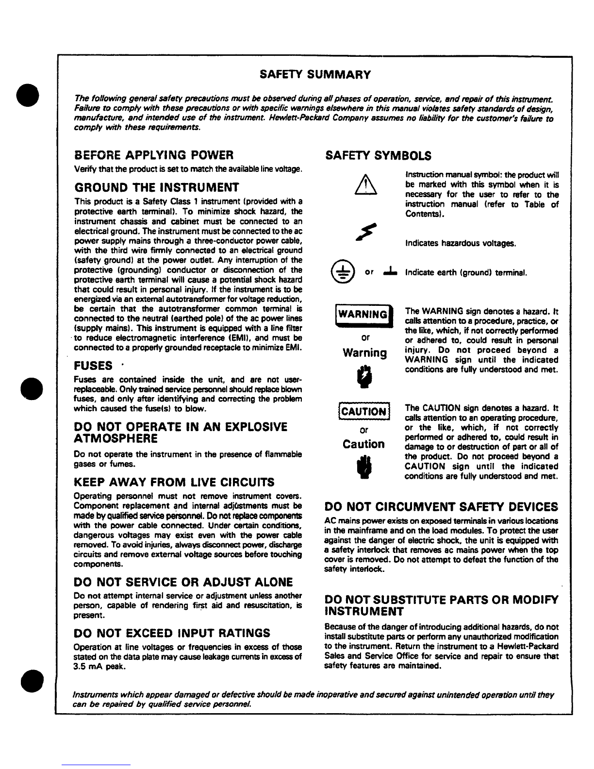
Instruction manual symbol: the product will
be marked with this symbol when it is
necessary
for
the user
to
refer to the
instruction manual (refer to
Table
of
Contents).
Indicates hazardous voltages.
@
or
.I.
Indicate earth (ground) terminal.
or
Warning
0
(CAUTION!
or
Caution
I
The WARNING sign denotes a hazard.
It
calls attention
to
aprocedure, practice,
or
the like, which,
if
not correctly performed
or adhered to, could result in personal
injury.
Do
not
proceed
beyond a
WARNING sign
until
the
indicated
conditions are fully understood
and
met.
The
CAUTION
sign denotes a hazard.
It
calls attention
to
an
operating procedure,
or
the like, which,
if
not correctly
performed or adhered
to,
could result in
damage
to
or
destruction
of
part
or
all
of
the product. Do not proceed beyond a
CAUTION sign
until
the
indicated
conditions are fully understood
and
met.
DO NOT
CIRCUMVENT
SAFETY DEVICES
AC
mains powerexists
on
exposed terminals in various locations
in the mainframe and on the load modules.
To
protect the user
against the danger of electric shock, the unit is equipped with
a safety interlock that removes ac mains power when the
top
cover is removed. Do not attempt
to
defeat the function
of
the
safety interlock.
DO
NOT
SUBSTITUTE PARTS OR MODIFY
INSTRUMENT
Because
of
the danger
of
introducing additional
hazards,
do
not
install substitute parts
or
perform any unauthorized modification
to
the instrument. Return the instrument
to
a Hewlett-Packard
Sales
and Service Office for service and repair
to
ensure
that
safety features are maintained.
Instruments
which
appeardamaged
or
defective should
be
made inoperative
and
sscuredagainst unintendedoperation unrilthey
can
be
repaired
by
qualifiedservice personnel.

TABLE
OF
CONTENTS
•
Section
Page
No.
Section
Pa~1e
No.
I
GENERAL
INFORMATION
1-1
IV
PRINCIPLES
OF
OPERATION
1-l
DescriptiOn
1-1
4-8
Simplified
Schematic
'l-3
1-6
Specifications
1-1
4-10
Detailed
Circuit
Analysis
4-3
1-8
Options
1-1
4-11
Preregulator
and
Control
Circuit•l-3
1-10
Accessories
1-2
4-19
Series
Regula
tor
•l-5
1-12
Instrument
Identification
1-2
4-21
Constant
Voltage Input
Circuit
4
1-5
1-15
Ordering
Additional
Manuals
1-2
4-26
ConstantCurrent
Input
Circuit
•l-6
4-31
Gating
Circuit
<l-7
II
INSTALIATION
2-1
4-34
Error Amplifiers
4-7
2-1
Initial
Inspection
2-1
4-37
Fault
Input
Circuit
4-7
2-3
Mechanical
Check
2-1
4-42
Reference
Circuit
·~-8
2-5
Electrical
Check
2-1
4-46
Meter
Circuit
·1-8
2-7
Installation
Data
2-1
2-9
Location
2-1
v
MAINTENANCE
s-1
2-11
Rack
Mounting
2-1
5-1
Introduction
S-1
2-15
Input
Power Requirements
2-2
S-3
General
Measurement
2-17 SOHz
Operation
2-2
Techniques
!S-1
2-19
Power
Cable
2-2
5-:.8
Test
Equipment Required
:S-1
2-22
Repackaging
for
Shipment
2-2
s-10
Performance
Test
:S-3
5-12
Constant
Voltage
Tests
S-4
III
OPERATING
INSTRUCTIONS
3-1
S-21
Constant
Current
Tests
S-6
3-1
Operating
Controls
and
S-25
Troubleshooting
S-6
Indicators
3-1
5-27
Trouble
Analysis
S-7
3-3
Operating
Modes
3-1
S-34
Repair
and
Replacement
S-7 •
3-S Normal
Operating
Mode
3-1
S-36
Adjustment
and
Calibration
S-13
3-7
Constant
Voltage.
3-1
S-38
Meter
Zero
S-13
3-9
Constant
Current
3-1
S-40
Voltmeter Tracking
S-13
3-11
Connecting
Load
3-2
S-42
Ammeter
Tracking
S-13
3-14
Operation
of
Supply
Beyond
S-44
Constant
Voltage
Programming
Rated
Output
3-2
Current
S-14
3-16
Optional
Operating
Modes
3-2
S-46
Constant
Current
Programming
3-17
Remote Programming.
Constant
Current
S-14
Voltage
3-2
S-48
Overvoltage
Trip
S-14
3-24
Remote Programming.
Constant
S-50
Transient
Recovery Time
S-14
Current
3-3
S-52
Preregulator
Tracking (60 Hz
3-30
Remote S.ensing
3-3
Operation)
5-14
3-35
Series
Operation
3-4
S-54
Preregulator
Tracking
(SO
Hz
3-39
Parallel
Operation
3-5
Operation)
5-14
3-42
Auto-Tracking
Operation
3-5
3-45
Special
Operating
Cons1derat10ns3-6
VI
REPIACEABLE
PARTS
6-1
3-46
Pulse
Loadin;
3-6
6-1
Introduction
6-1
3-48
Output
Capacitance
3-6
6-4
Ordering Information
6-1
3-51
Reverse
Voltage Loading
3-6
Reference
Designators
3-53
Reverse
Current
Loading
3-6
Abbreviations
Manufacturers
IV
PRINCIPLES
OF
OPERATION
4-1
6-8
Code
List
of
Manufacturers
6-2
4-1
Overall
Block Diagram
Parts
List
Table
Discussion
4-1
•
11

•
•
•
SECTION I
GENERAL
INFORMATION
1-1
DESCRIPTION
1-2
This power
supply
is
completely
tran-
sistorized
and
suitable
for either bench
or
relay
rack
operation.
It
is
a compact,
well-regu-
lated.
Constant
Voltage/
Constant Current supply
that
will
furnish full
rated
output
voltage
at
the
maximum
rated
output
current or
can
be
conUnuous-
1y
adjusted
throughout the output range. The front
panel
CURRENT
controls
can
be
used
to
establish
the
output
current
limit
(overload or
shon
circuit)
when
the
supply
is
used
as
a
constant
voltage
source
and
the
VOLTAGE
control
can
be uaed to
establish
the
voltage
limit
(ce1Ung)
when the
sup-
ply
is
used
as
a
constant
current
source.
The
supply
will
automatically
crossover
from
constant
voltage
to
constant
current operation and Vice
versa
if
the
output
CUITant
or voltage exceeds
these
preset
limits.
1-3
The power
supply
has
both front and
rear
terminals.
Either
the
positive
or
negative output
terminal may
be
qrounded or the power supply can
be
operated
floating
at
up to a
maximum
of 300
volts
off
ground.
1-4
A
single
meter
is
used
to measure either
out-
put
voltage
or
output current
in
one
of
two ranges.
The
voltage
or
current
ranges are
selected
by a
METER
switch
on
the
front panel.
1-S
Barrier
strip
terminals located
at
the
rear
of
the
unit
allow
ease
in
adapting
to
the many oper-
ational
capabiUU~s
of
the power supply. A brief
description
of
these
capabilities
is
given below:
a.
Remote Programming
The power
supply
may
be
programmed
from a remote
location
by means
of
an
external
voltage
source
or
resistance.
b.
Remote
Sensing
The degradation
in
regulation which
would
occur
at
the
load
because
of the voltage
drop
in
the
load
leads
can
be
reduced by using the
power
supply
in
the
·remote sensing mode of oper-
ation.
1-1
c.
Series
and
Auto-Series
Operation
Power
supplies
may be
used
in
series
when
a higher
output
voltage
is
required in the
voltage
mode
of
operation
or
when
greater
voltage
compliance
is
required
in
the
constant
current
mode
of
operation.
Auto-Series
operation
permits
one
knob
control
of
the
total
output
voltage
from
a
"master"
supply.
d.
Parallel
and
Auto-Parallel
Qperation
The power
supply
may be operated in
parallel
with a
similar
unit
when
greater
output
current
capability
is
required.
Auto-Parallel
op-
eration
permits
one
knob control
of
the
total
out-
put
current
from a
"master"
supply.
e.
Auto-Track1n9
The power
supply
may
be
used
as a
"master"
supply.
havin9 control
over
one
(or
more)
"slave"
supplies
that
furnish
various
voltages
for a
system.
1-6
SPECifJCATIONS·
1-7
Detailed
specifications
for
the
power supply
are
given
in
Table
1-1.
i-s
omoNS
1-9
Options
are
factory
modifications of a
standard
instrument
that
are
requested
by the
customer.
The
follOWirlCJ
options
are
available
for
the
instrument covered
by
this manual.
Where
necessary.
detailed
covera9e
of
the options
is
included
throughout
the
manual.
Option
No.
OS
Description
SO
Hz
Regulator Realignment:
Standard
instruments
will
operate
saUsfactorily
at
both 60 and 50
Hz
without
adjustment.
However
Op-
tion
05
factory
reall9nment
results
in
more
efficient
operation
at
50 Hz,
and
is
recommended for
all
applica-
tions
when
continuous
operation
from
a
SO
Hz
ae
input
is
intended
.

Option No.
07
08
09
11
13
14
18
Description
Voltage
10-Tum
Control:
A
single
control
that
replaces
both
coarse
and
fine
voltage
controls
and
improves
output
settability.
Current
l
'7'-Turn
Control:
A
single
control
that
replaces
both
coarse
and
fine
current
controls
and
improves
output
settablllty.
Voltage
and
Current
10-Tum
Con-
trols:
Options
07
and
08 on
same
instrument.
Intema
1
Overvoltage
Protection
"Crowbar".
Operating
and
Service
information
is
included
1n
Appendix A
at
the
rear
of
the
manua
1.
Three
Digit
Graduated
Decadial
Voltage
Control:
Control
that
re-
places
10-tum
voltage
control
per-
mitting
accurate
resettability.
Three
Digit
Graduated
Decadial
Current
Control:
Control
that
re-
places
coarse
and
fine
current
con-
trols
permitting
accurate
resettability.
230V
AC,
Single
Phase,
Input:•
Sup-
ply
is
shipped
for
llSV
ac
operation.
Option 18
consists
of
modifying
the
supply
for 230Vac
operation.
1-10
ACCESSORIES
1-11
The
accessories
listed
in
the
following
chart
may
be
ordered
with
the
power
supply
or
separately
from your
local
Hewlett-Packard
field
sales
office
(refer
to
list
at
rear
of
manual for
ad-
1-2
c:lres
ses).
i Part
No.
14SlSA
1452SA
Description
Rack
Kit
for mounting one
Si"
high supply. (Refer
to
Section II
for
details.
)
Rack
Kit
for mounting two
Si"
high
supplies.
(Refer to Section
II
for
details.
)
1-12
INSTRUMENT IDENTIFICATION
1-13
Hewlett-Packard
power supplies are
identi-
fied
by a
three-part
serial
number tag. The
first
part
is
the power
supply
model number. The
i;ec-
ond
part
is
the
serial
number prefix, which co•n-
sists
of a
number-letter
combination that denc>tes
the
date
of
a
significant
design change. The
num-
ber
designates
the
year,
and
th,e
letter
A through M
designates
the
month, January.through December
respectively.
The
third
part
is
the power
supply
serial
number.
1-14
If
the
serial
number prefix on your power
supply
does
not
agree
with the prefix on
the
title
page
of
this
manual, change
sheets
are
included
to
update
the
manual. Where applicable, bac:k-
dating
information
is
given in an appendix
at
the
rear
of
the manual.
1-lS
ORDERING
ADDITIONAL
MANU~
1-16
One
manual
is
shipped
with
each
power
supply.
Additional manuals may be purchased
from your
local
Hewlett-Packard field office
(see
list
at
rear
of
this
manual for
addresses).
Specify
the
model number,
serial
number prefix, and
G~
stock
number provided on the Utle page.
•
•
•

•
•
•
Table
1-1.
Specifications
INPUT:
105-125
VAC.
single
phase,
50-60Hz,
4. SA,
250W•
OUTPUT:
0-60
volts@
0-3
amps.
LOAD
REGULATION:
Constant
Voltage
--
Less
than
0.
01%
plus
l
mV
for a
full
load
to
no
load
change
in
output
current.
Constant
Current
--
Less
than
0.
05%
plus
lmA
for
a
zero
to
maximum
change
in
output
voltage.
LINE
REGUIATION:
Constant
Voltage
--
Less
than
0.
01%
plus
lmV
for
any
line
voltage
change
within
the
input
rating.
Constant
Current
--
Less
than
O.
05%
plus
lmA for
any
line
voltage
change
within
the
input
rating,
RIPPLE
AND
NOISE:
Constant
Voltage
--
Less
than
500t£V
rms.
Constant
Current
--
Less
than
3mA
nns.
OPERATING
TEMPERATURE
RANGES:
Operating:
o
to
sooc.
Storage:
-20
to
+ssoc.
TEMPERATURE
COEFFICIENT:
Constant
Voltage
--
Less
than
O.
02%
plus
S0011V
?er
degree
Centigrade.
Constant
Current
--
Less
than
O.
02%
plus
l.
5mA
per
degree
Centigrade.
STABILI'IY:
Constant
Voltage
--
Less
than
0.10%
plus
2.
5mV
total
drift
for 8
hours
after
an
initial
warm-
up time
of
30
minutes
at
constant
ambient.
con-
stant
line
voltage.
and
constant
load.
Constant
Current
--
Less
than
O.
10%
plus
7.
SmA
total
drift
for 8 hours
after
an
initial
warm-
up time
of
30
minutes
at
constant
ambient,
con-
stant
line
voltage,
and
constant
load.
INTERNAL
IMPEDANCE
AS
A
CONSTANT
VOLTAGE
SOURCE:
Less
than
O.
001 ohm from
DC
to
lOOHz.
Less
than
O.
01
ohm from
lOOHz
to
lkHz.
Less
than
0. 2
ohm
from
lkHz
to
lOOkHz.
Less
than
2.
0 ohms
f~m
l
00
kHz to 1 MHz.
TRANSIENT
RECOVERY
TIME:
Less
than
50~sec
for
output
recovery
to
with-
in 15
mv
following
a
current
change
in
the
output
equal
to
the
current
rating
of
the
supply
or
5
amperes,
whichever
is
smaller
•
OVERLOAD
PROTECTION:
A
continuously
acting
constant
current
cir-
cuit
protects
the
power
supply
for
all
overloads
1-3
including a
direct
short
placed
across
the
termi-
nals
in
constant
voltage
operation,
The
constant
voltage
circuit
limits
the
output
voltage
in
the
constant
current
mode
of
operation.
METER:
The front
panel
meter
can
be
used
as
either
a
0-70
or
0-7
volt
voltmeter
or
as
a
0-4
or
0-0.
4
amp ammeter.
OUTPUT
CONTROLS:
Coarse
and fine
voltage
controls
and
coarse
and
fine
current
controls
provide
continuous
ad-
justment
over
the
entire
output
span.
OUTPUT
TE™INALS:
Three
"five-way"
output
posts
are
provided
on
the
front
panel
and
an
output
terminal
strip
is
located
on
the
rear
of
the
chassis.
.All power
supply
output
terminals
are
isolated
from
the
chassis
and
either
the
positive
or
negative
termi-
nal
may
be
connected
to
the
chassis
through a
separate
ground
terminal.
If
the
front
panel
ter-
minals
are
used.
the
load
regulation
will
be
O.SmV
per
ampere
greater.
due
to
the front
terminal
re-
sistance.
ERROR
SENSING:
Error
sensing
is
normally
accomplished
at
the
front
terminals
if
the
load
is
attached
td
the
front
or
at
the
rear
terminals
if
the
load
is
attach-
ed
to
the
rear
terminals.
Also.
provision
is
in-
cluded
on
the
rear
tenainal
strip
for remote
sens-
ing.
REMOTE
PROGRAMMING:
Remote programming of
the
supply
output
at
approximately
300
ohms
per
volt
in
constant
volt-
age
is
made
available
at
the
rear
terminals.
In
constant
current
mode
of
operation.
the
current
can
be
remotely
programmed
at
approximately
500 ohms
per
ampere.
COOLING:
Convection
cooling
is
employed. The
sup-
ply
has
no
moving
parts.
SIZE:
5}" H x 16" D x
Si"
W.
Two
of
the
units
can
be
mounted
side
by
side
in a
standard
19"
relay
rack.
WEIGHT:
29
lbs.
net. 38
lbs.
shipping.
FINISH:
Light
gray
front
panel
with dark.
gray
case.
POWER
CORD:
A
three-wire,
five-foot
power
cord
is
pro-
vided
with
each
unit.

•
•
•
SECTION
II
INSTALLATION
2-1
INITIAL INSPECTION
2-2
Before
shipment,
this
instrument
was
inspected
and
found
to
be
free
of
mechanical
and
electrical
defects.
As
soon
as
the
instrument
is
unpacked,
in-
spect
for
any
damage
that
may
have
occurred
in
transit.
Save
all.
packing
materials
until
the
inspec-
tion
is
completed.
If
damage
is
found.
proceed
as
described
in
the
Claim
for
Damage
in
Shipment
sec-
tion
of
the
warranty
page
at
the
rear
of
this
manual.
2-3
MECHANICAL
CHECK
2-4
This
check
should
confirm
that
there
are
no
broken
knobs
or
connectors,
that
the
cabinet
and
panel
surfaces
are
free
of
dents
and
scratches,
and
that
the
meter
is
not
scratched
or
cracked.
2-5
ELECTRICAL
CHECK
2-6
The
instrument
should
be
checked
against
its
electrical
specifications.
SectionV
includesan"in-
cabinet"
performance
check
to
verify
proper
instrument
operation.
2-7
INSTALLATION
DATA
2-8
The
instrument
is
shipped
ready
for
bench
operation.
It
is
necessary
only
to
connect
the
in-
strument
to
a
source
of
power
and
it
is
ready
for
operation.
2-9
LOCATION
2-10·
This
instrument
is
air
cooled.
Sufficient
space
should
be
allotted
so
that
a free flow
of
cooling
air
can
reacn
the
sides
anci
rear
of the
ins
trumenc
when
itis
inoperation.
It
should
be
used
in
an
area
where
the
ambient
temperature
does
not
exceed
sooc.
2-11
RACK
MOUNTING
2-12
This
instrument
may
be
rack
mounted
in
a
standard
19
inch
rack
panel
either
alongside
a
sim-
ilar
unit
or
by
itself.
Figures
2-1
and
2-2
show
how
both
types
of
installations
are
accomplished.
2-13
To
mount
two
units
side-by-side,
proceed
as
follows:
a.
Remove
the
four
screws
from
the
front
panels
of
both
units.
b.
Slide
rack
mounting
ears
between
the
front
panel
and
case
of
each
unit.
c.
Slide
combining
strip
between
the
front
panels
and
cases
of
the
two
units.
d. After
fastening
rear
portions
of
u_nits
to-
gether
using
the
bolt,
nut,
and
spacer,
replace
pan-
el-
screws
•
RAC!(
EM
-0
8
-0
....
--
-·
..
6el
-0
COllllNlltG
STlllP
Figure
2-1.
Rack
Mounting,
Two
Units
2-1
-·
0

I
Q
ti
0 •
r-¥0L.TACE-,
C.OAAS(
r1-.[
(j
(j
0
10
.1
•
....
0
c
I
cl
Q
Figure
2-2.
Rack
Mounting,
One
Unit
2-14
To
mount a
single
unit
in
the
rack
panel,
proceed
as
follows:
a.
Bolt
rack
mounting
ears.
combining
straps,
and
angle
brackets
to
each
side
of
center
spacing
panels.
Angle
brackets
are
placed
be-
hind
combining
straps
as
shown in Figure
2-2.
b.
Remove four
screws
from
front
panel
of
unit.
c.
Slide
combining
strips
between
front
panel
and
case
of
unit.
d.
Bolt
angle
brackets
to
front
sides
of
case
and
replace
front
panel
screws.
2-15
INPUT
POWER
REQUIREMENTS
2-16
This
power
supply
may
be
operated
from
either
a nominal 115
volt
or
230
volt
50-60
cycle
power
source.
The
unit,
as
shipped
from
the
fac-
tory,
is
wired
for
115
volt
operation
only.
A
factory
modification
(Option 18) must
be
made
to
permit
operation
from a 230
volt
line.
The input
power
required
when
operated
from a
llS
volt,
60
cycie
power
source
at
full
load
is
given
in
the
s~ecification
table
in
Section
I.
2-17
SO
Hz
OPERATION
2-18
Theunit
as
normally
shipped
from
the
factory
can
be
operated
from
either
a
50
or
60
Hz
source.
However,
with a 50 Hz
input,
the
operation
of
the
unit
may
become
somewhat deqraded
when
the
temperature
exceeds
350
Centigrade
(instead
of
the
normal
soocentigrade
capability
with a 60 Hz input).
To
permit
optimum
operation
at
50
Hz,
the
unit must
2-2
be
realigned.
This
realignment
procedure
is
de-
scribed
in
Paragraph
5-54
at
the
rear
of
the·manual.
2-19
POWER
CABLE
2-20
To
protect
operating
gersonnel,
the
National
Electrical
Manufacturers'
Association
(NEMA)
recommends
that
the
instrument
panel
and
ca:binet
be
grounded.
This
in&trument
is
equiPped
with
a
three
conductor
p01Ner
cable.
The
third
cond·uctor
is
the
ground
conductor
and
when
the
cable
is
•
plugged
into
an
appropriate
receptacle,
the
in-
strument
is
grounded. The
offset
pin
on the power
cable
three-prong
connector
is
the
ground
connec-
tion.
2-21
To
preserve
the
protection
feature
when
op-
erating
the
instrument
from a
two-contact
outlet,
use
a
three-prong
to
two-prong
adapter
and
c:on-
nect
the
green
lead
on the
adapter
to
ground.
2-22
REPACKAGING
FOR
SHIPMENT
2-23
To
insure
safe
shipment
of
the
instrument,
it
is
recommended
that
the
package
designed
for
the
instrument
be
used.
The
original
packaging
material
is
reusable,
If
it
ls
not
available,
con-
tact
your
local
Hewlett-Packard
field
office
~:o
obtain
the
materials.
This
office
will
also
furnish
the
address
of
the
nearest
service
office
to
which
the
iT\strument
can
be
shipped.
Be
sure
to
attach
a
tag
to
the
instrument
which
specifies
the o·wn-
er,
model number, full
serial
number,
and
SE~rvice
required,
or
a
brief
description
of
the
troublE!.
•

•
•
•
SECTION
III
OPERATING
INSTRUCTIONS
3-1
OPERATING
CONTROLS
AND
INDICATORS
3-2
The front panel
controls
and
indicators,
to-
gether
with
the
normal
turn-on
sequence,
are
shCM'n
in Figure
3-1.
0
ll(f(I
TURN-ON
SEQUENCE
I.
PUSH
ON/OFF
BUTTON
ANO
BUTTON
SHOULO
LIGHT.
2.
SET
METER
SWITCH
TO
C&SIREO
VOLTAGt
llAN'GE.
3.
ADJUST
COARSE
AND
nNE
VOLTAGE
CONTROLS
UNTIL
lXSllED
OUTPUT
VOLTAGE
IS
INOICATl:D
ON
METER
•
~.
SET
METER
SWITCH
DESIRED
CURRENT
ltANGt
AND
SHORT
CIR•
CUIT
OUTPUT
TERMINALS.
s.
ADJUST
CURRENT
CONTROLS
f'OR
cc;nu;o
OUTPUT
ci.nuu:m.
~.
R.CMOV!:
SHORT
AND
CONNECT
~TO
OUTPUT
TERMINALS
ll'RONT
OR
REAR!.
Figure
3-1.
Front Panel Controls and
Indicators
3-3
OPERAnNG MODES
3-4
The power
supply
is
desiqned so
that
its
mode
of
operation
can
be
selected
by
making
strapping
conne~tions
between
particular
terminals
on
the
terminal
strip
at
the
rear
of
the power
sup-
ply.
The terminal
designations
are
stenciled
in
white
on
the
power
supply
above
their
respective
terminals.
Although
the
strapping
patterns
Ulus-
trated
in
this
section
show the
positive
terminal
grounded,
the
operator
can
ground
either
terminal
or
operate
the
power
supply
up
to
300 vdc off
ground
(floating). The following paragraphs
de-
scribe
the
procedures
for utilizing the various
operational
capabilities
of
the power supply. A
more
theoretical
description
concerning the
oper-
ational
features
of
this
supply
is
contained
in a
power
supply
Application Manual and in
various
Tech.
Letters
published
by
the
Harrison Division.
Copies
of
these
can
be
obtained from your
local
Hewlett-Packard
field
office.
3-1
3-5
NORMAL
OPERATING
MODE
3-6
The power supply
is
normally shipped with
its
rear
terminal
strapping connections arranged
for
Constant
Voltage/Constant
Current, local
sensing,
local
programming, single unit
mode
of
operation.
This
strapping pattern
is
illustrated
in
Figure
3-2.
The operator
selects
either
a
constant
voltage
or
a
constant
current
output using the front
panel
controls
Oocal
programming, no strapping
changes
are
necessary}.
Figure
3-2.
Normal Strapping Pattern
3-7
CONSTANT
VOLTAGE
3-8
To
select
a
ronstant
voltage output,
proceed
as
follows:
a.
Turn-on power supply and
adjust
VOLTAGE
controls
for
desired
output voltage {out-
put
terminals
open).
b.
Short
output
terminals and
adjust
CUR-
RENT
controls
for maximum output current
allow-
able
(current
limit),
as
determined by load
condi-
tions.
If
a
load
change
causes
the
current limit
to
be
exceeded,
the
power
supply
will
automatically
crossover
to
constant
current
output
at
the
preset
current
limit
and
the
output
voltage
will
drop
pro-
portionately,
In
setting
the
current limit,
allow-
ance
must
be
made for high peak current which
can
cause
unwanted
cross-over.
(Refer to Paragraph
3-46).
3-9
CONSTANT
CURRENT
3-10
To
select
a
constant
current output.
pro-
ceed
as
follows:
·
a.
Short output terminals and
adjust
CUR-
RENT
controls
for
desired
output current.

b. Open
output
terminals
and
adjust
VOLTAGE
controls
for maximum
output
voltage
al-
lowable
(voltage
limit),
as
determined
by
load
conditions.
If
a
load
change
causes
the
voltage
limit
to
be
exceeded,
the
power
supply
will
auto-
matically
crossover
to
constant
voltage
output
at
the
preset
voltage
limit
and
the
output
current
will
drop
proportionately.
In
setting
the
voltage
limit,
allowance
must
be
made
for
high
peak
voltages
which
can
cause
unwanted
crossover.
(Refer
to
Paragraph
3-46).
NOTE
When
Model
6291A
is
operated
continuously
in
the
crossover
region.
between
Constant
Voltage/Con-
stant
Current,
the
feedback
loop
may
break
into
os-
cillation;
particularly
in
the
0.
SA
to
l.
SA
output
current
range. Although
the
crossover
region
is
not
usually
an
area
of
continuous
operation,
this
prob-
lem
can
be
eliminated,
if
necessary,
by
connecting
the
emitter
of
Q300
to
+S
(instead
of
to
the
emitter
of
Q301)
and
readjusting
R307.
Note
that
when
this
is
done,
the
transient
recovery
time
of
Model
6291A
must
be
derated
to
"SOµsec
for
recovery
to
within
25mV"
(instead
of
lSmV).
3-11
CONNECTING LOAD
3-12
Each
load
should
be
connected
to
the
power
supply
output
terminals
using
separate
pairs
of
connecting
wires.
This
will
minimize
mutual
cou-
pling
effects
between
loads
and
will
retain
full
advantage
of
the
low
output
impedance
of
the
power
supply.
Each
pair
of
connecting
wires
should
be
as
short
as
possible
and
twisted
or
shielded
to
reduce
noise
pickup.
(If
shield
is
used,
connect
one
end
to
power
supply
ground
terminal
and
leave
the
other
end
unconnected.
)
3-13
If
load
considerations
require
that
the
out-
put
power
distribution
terminals
be
remotely
located
from
the
power
supply,
then
the
power
supply
output
terminals
should
be
connected
to
the
remote
distribution
'terminals
via
a
pair
of
twisted
or
shielded
wlres
and
each
load
separate-
ly
connected
to
the
remote
distribution
terminals.
For
this
case.
remote
&ensing
should
be
used
{Paragraph
3-30).
3-14
OPERATION
OF
SUPPLY
BEYOND
RATED
OUTPUT
3-15
The
shaded
area
on
the
front
panel
meter
face
indicates
the
amount
of
output
voltage
or
current
that
is
available
in
excess
of
the
normal
output.
Althouoh
the
supply
can
be
operated
in
this
shaded
region
without
being
damaged,
it
can-
not
be
guaranteed
to
meet
all
of
its
performance
specifications.
Hawever,
if
the
line
voltage
is
maintained
above
115 Vac,
the
supply
wil~proba
bly
operate
within
its
specifications.
3-2
3-16
OPTIONAL
OPERATING
MODES
3-17
REMOTE
PROGRAMMING, CONSTANT
VOl~T
AGE
3-18
The
constant
voltage
output
of
the
power
supply
can
be
programmed (controlled) from a
remote
location
if
required. Either a
resistance
or
voltage
source
can
be
used
for
the
programming
device.
The
wires
connecting
the
programming
terminals
of
the
supply
to
the
remote programmir1g
device
should
be
twisted
or
shielded
to
reduce
noise
pick-up.
The
VOLTAGE
controls
on
the
front
panel
are
disabled
according
to
the
followi.ng
procedures.
~
~
~
+·
+
G - -
~
~
M M M
~
M
1°1~1~1
PROGRAMMING
RESISTat
Figure
3-3.
Remote
Resistance
Programming
(Constant
Voltage)
3-19
Resistance
Programming (Figure
3-3).
In
this
mode.
the
output
voltage
will
vary
at
a
rate
•
determined
by
the
programming
coefficient,
200
•
ohms
per
volt
(300 ohms per
volt
for
Model
6296A).
The
output
voltage
will
increase
l
volt
for
each
200 ohms (or
300
ohms) added
in
series
with
the
programming
terminals.
The programming
coeffi--
cient
is
determined
by
the pr09rammin9
current.
This
current
is
factory
adjusted
to
within
2%
of
S ma
(2%
of
3. 3 ma
for
Model 6296A).
If
greater
programming
accuracy
is
required,
it
may
be
achieved
by
changing
resistor
R806.
3-20
The
output
voltage
of
the
power
supply
should
be
zero
volts
z20
millivolts
when
zero
ohms
is
connected
across
the
programming termi·-
nals.
3-21
To
maintain
the
stability
and
temperature
coefficient
of
the
power
supply,
use
programmin~;
resistors
that
have
stable,
low
noise,
and
low
temperature
(less
than
30 ppm
per
degree
Centi-
grade)
characteristics.
A
switch
can
be
used
in
conjunction
with
various
resistance
values
in
order
to
obtain
discrete
output
voltages.
The
switch
should
have
make-before-break
contacts
to
avoid
momentarily
opening
the
programming
terminals
during
the
switching
interval.
3-22
Voltage Programming (Figure
3-4).
Employ
the
strapping
pattern
shown
on
Figure
3-4
for
. •
voltage
programming. In
this
mode,
the
output
voltage
will
vary
in
a
1
to
1
ratio
with
the
pro-

•
•
•
;ramming
voltage
(reference
voltage)
and
the load
on
the
programming
voltage
source
will
not
exceed
25
microamperes.
Al
46
A2
+
+
G - -
•S
AJ
A4
AS
A6
A7
Al
101~1r1m1
VOLTAGE
SOURCE
Figure
3-4.
Remote Voltage Programminq
(Constant
Voltage)
3-23
The
impedance
matching
resistors
(Rx)
for
the
programming
voltage
source
should
be
approx-
imately
1000
ohms
to
maintain
the
temperature
and
stability
specifications
of
the
power supply.
3-24
REMOTE
PROGRAMMING,
CONSTANT
CUR-
RENT
3-25
Either
a
resistance
or a
voltage
source
can
be
used
to
control
the
constant
current
output
of
the
supply.
The
CURRENT
controls
on
the
front
panel
are
disabled
according
to
the
following
pro-
cedures
•
PROGRAMMING
lu:slStoR
Fiqure
3-S.
Remote
Resistance
Programming
(Constant
.Current)
3-26
Resistance
Pn?qrammins (Figure
3-5).
In
this
mode,
the
output
current
varies
at
a
rate
determined
by
the
programming
coefficient
--
100
ohms
per
ampere
for
Models
6282A
and
6286A, 200
ohms
per
ampere
for
Models
6285A
and
6291A,
and
500
ohms
per
ampere
for
Models
6290A
and
6296A.
The
programming
coefficient
ls
determined
by the
Constant
Current
programming
current
l
mA
for
Models
~282A,
6285A, 6286A,
and
6291A
or
O.
66
mA
for
Models
6290A
and
6296A. This
current
is
adjusted
to
within
10%
at
the
factory.
If
qreater
programming
accuracy
is
required,
it
may
be
achieved
by
changing
resistor
R808
as
outlined
in
Section
V.
3-27
Use
stable,
low
noise,
low temperature
co-
efficient
(less
than
30
ppm/Oc) programming
re-
sistors
to
maintain
the
power
supply
temperature
3-3
coefficient
and
stability
specifications.
A
switch
may
be
used
to
set
discrete
values
of
output
cur-
rent.
A
make-before-break
type
of
switch
should
be
used
since
the
output
current
will
exceed
the
maximum rating
of
the
power
supply
if
the
switch
contacts
open
during
the
switching
interval.
CAUTION
If
the
programming
terminals
(Al
and
A7)
should
open
at
any
time durinq
this
mode,
the
output
cur-
rent
will
rise
to a
value
that
may damage the power
supply
and/or
the
load. To
avoid
this
possibility,
connect
a lK
resistor
(1.
SK
for
Models
6290A
and
6296A)
across
the
programming
terminals.
Like
the
programming
resistor,
this
resistor
should be
of
the
low
noise,
low temperature
coefficient
type,
3-28
Voltage Programming (Figure
3-6).
In
this
mode.
the
output
current
will
vary
linearly
with
changes
in
the
programming
voltage.
The
pro-
gramming
voltage
should
not
exceed
1. 5
volts.
Voltage
in
excess
of 1. 5
volts
will
result
in
ex-
cessive
power
dissipation
in
the
instrument
and
possible
damage,
VOLtACE
SOURCE
Figure
3-6.
Remote Voltage Programming
(Constant
Current)
3-29
The
output
current
will
be
the programming
voltage
divided
by
the
internal
current
sampling
resistance
RSOO.
The
current
required
from
the
voltage
source
will
be
less
than
10 microamperes.
The impedance matching
resistor
(Rx)
should
be
approximately
1000 ohms
if
the
temperature
coeffi-
cient
and
stability
specifications
of
the power
supply
are
to
be
maintained.
3-30
REMOTE
SENSING
(See Figure 3-7)
3-31 Remote
sensing
is
used
to
maintain good
regulation
at
the
load
and
reduce
the
degradation
of
regulation
which
would
occur
due
to
the
voltage
drop
in
the
leads
between
the
power supply
and
the
load.
Remote
sensing
is
accomplished
by
utilizing
the
strapping
pattern
shown
in
Figure
3-7.
The
power
supply
should
be
turned
off
before
changing
strapping
patterns.
It
is
not
required

that
these
leads
be
as
heavy
as
the
load
leads.
However,
they
must
be
twisted
or
shielded
to
minimize
noise
pick-up.
Fiqure
3-7.
Remote
Sensing
CAUTION
Observe
polarity
when
connecting
the
sensing
leads
to
the load.
3-32
Note
that
it
is
desirable
to
minimize
the
drop in
the
load leads
and
it
is
recommended
that
th~
drop
not
exceed
1
volt
per
lead
if
the power
supply
is
to
meet
its
DC
specifications.
If a
larger
drop must be
tolerated,
please
consult
a
Hewlett-Packard
field
representative.
NOTE
Due
to
the
voltage
drop
in
the
load
leads,
it
may
be
necessary
to
re-
adjust
the
current
limit in
the
remote
sensing
mode.
3-33
The procedure
Just
described
will
result
in a
low DC
output
impedance
at
the
load.
If
a low
AC
impedance
is
required,
it
is
recommended
that
the
following
precautions
be
taken:
a.
Disconnect
output
capacitor
C803 by
disconnecting
the
strap
between
A2
and
+s.
b.
Connect
a
capacitor
having
similar
char-
acteristics
(approximately same
capacitance,
same
voltage
rating
or
greater, and having
good
high
frequency
characteristics)
across
the
load·using
short
leads,
3-34
Although
the
strapping
patterns
shown
in
Figures
3-3
through
3-6
employ
local
sensing,
note
that
it
is
possible
to
operate
a power
supply
simultaneously
in the remote
sensing
and
Constant
Voltage/Constant
Current remote proqramming
modes.
3-35
SERIES
OPERATION
3-36
Normal Series Connections (Figure
3-8).
Two or more power
supplies
can
be
operated
in
series
to
obtain
a higher voltage
than
that
avail-
able
from a
single
supply. When
this
connection
3-4
r"Al"""'l"'--r~r--.,..-..,.;;;...----....-..--.....-..,.;.;;~A6.;;.,.;117
U
~~~~c@
0
Figure
3-8.
Normal
Series
Connectii:>ns
•
is
used,
the
output
voltage
is
the
sum
of
the
voltaqes
of
the
individual
supplies.
Each:
of
the
individual
supplies
must
be
adjusted
in
oz'der
to
obtain
the
total
output
voltage.
The powe·r
supply
contains
a
protective
diode
connected
int~!mally
across
the
output
which
protects
the
supply
if
one
power
supply
is
turned off while
its
serie:;
part-
ner(s)
is
on.
3-37
Auto-Series
Connections
(Figure
3-~ll..
The
Auto-Series
configuration
is
used
when
it
is
de-
sirable
to
have
the
output
wltage
of
each
of
the
series
connected
supplies
vary
in accordc1nce
with
the
setting
of
a
control
unit. The
control
unit
is
called
the
master;
the
controlled
units
arE!
called
slaves.
At maximum output
voltage,
the
voltage
of
the
slaves
is
determined
by
the
setting
of
the
front
panel
VOLTAGE
control
on the
mastei~.
Th.
master
supply
must
be
the
most
positive
supply
the
series.
The
output
CURRENT
controls
of
all
series
units
are
operative
and
the
current
limit
is
equal
to
the
lowest
control
setting.
U
any
output
CURRENT
controls
are
set
too
low,
automatic
crossover
to
constant
current
operation
wl.11
occur
and
the
output
voltage
will
drop, Remote
sensing
and
programming
can
used:
however,
the
strapping
arrangements
shown in
the
applicable
fig1J.res show
local
sensing
and
programming.
Al
0
MASTER
0
St.\VE
Al
Figure
3-9.
Auto-Series,
Two
Units
•
Table of contents
Other HP Power Supply manuals