HTW ECO-THERMAL R32 Series Product guide

ECO-THERMAL R32
HTW-V5WD2N8 |HTW-V7WD2N8 |HTW-V12WD2N8
HTW-V16WD2N8 |HTW-V16WD2RN8
EN DATABOOK
Please, read carefully this manual before using the product.
Thank you

CONTENTS
Part 1 General Information............................................................................ 3
Part 2 Engineering Data ............................................................................... 19
Part 3 Installation andField Settings.......................................................... 48


Part 1
General Information
1 M-Thermal Mono System........................................................................... 4
2 Unit Capacities ........................................................................................... 6
3 Nomenclature ............................................................................................ 6
4 System and Design Unit Selection .............................................................. 7
5 Typical Applications ................................................................................... 9
3

1M-Thermal Mono System
1.1 System Schematic
Figure 1-1.1: System schematic
M-Thermal Mono is an integrated air-to-water space heating, space cooling and domestic hot water heat pump system.
The outdoor heat pump system extracts heat from the outdoor air and transfers this heat through refrigerant piping to the
plate heat exchanger in the hydronic system. The heated water in the hydronic system circulates to low temperature heat
emitters (floor heating loops or low temperature radiators) to provide space heating, and to the domestic hot water tank
to provide domestic hot water. The 4-way valve in the outdoor unit can reverse the refrigerant cycle so that the hydronic
system can provide chilled water for cooling using fan coil units.
The heating capacity of heat pumps decreases with ambient temperature. M-Thermal Mono can be equipped with a
backup electric heater to provide additional heating capacity for use during extremely cold weather when the heat pump
capacity is insufficient. The backup electric heater also serves as a backup in case of heat pump malfunction and for
anti-freeze protection of the outside water piping in winter.
4

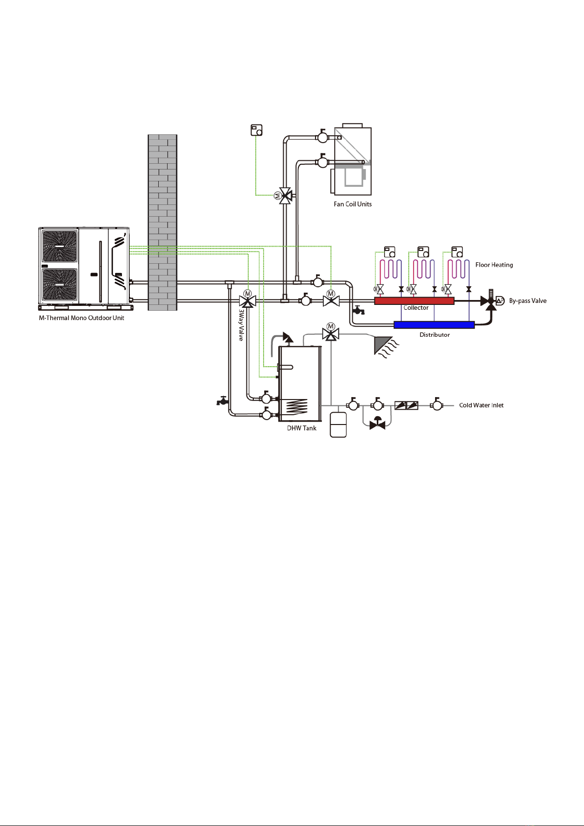
1.2 System Configurations
M-Thermal Mono can be configured to run with the electric heater either enabled or disabled and can also be used in
conjunction with an auxiliary heat source such as a boiler.
The chosen configuration affects the size of heat pump that is required. Three typical configurations are described below.
Refer to Figure 1-1.2.
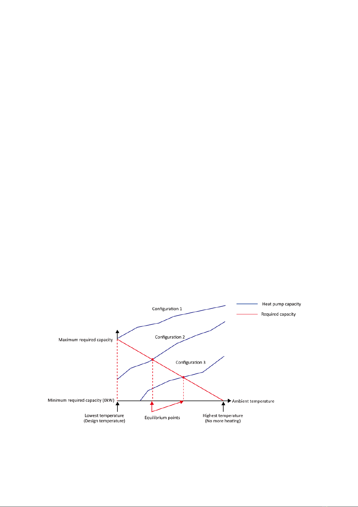
Configuration 1: Heat pump only
The heat pump covers the required capacity and no extra heating capacity is necessary.
Requires selection of larger capacity heat pump and implies higher initial investment.
Ideal for new construction in projects where energy efficiency is paramount.
Configuration 2: Heat pump and backup electric heater
Heat pump covers the required capacity until the ambient temperature drops below the point at which the heat
pump is able to provide sufficient capacity. When the ambient temperature is below this equilibrium point (as shown
in Figure 1-1.2), the backup electric heater supplies the required additional heating capacity.
Best balance between initial investment and running costs, results in lowest lifecycle cost.
Ideal for new construction.
Configuration 3: Heat pump with auxiliary heat source
Heat pump covers the required capacity until the ambient temperature drops below the point at which the heat
pump is able to provide sufficient capacity. When the ambient temperature is below this equilibrium point (as shown
in Figure 1-1.2), depending on the system settings, either the auxiliary heat source supplies the required additional
heating capacity or the heat pump does not run and the auxiliary heat source covers the required capacity.
Enables selection of lower capacity heat pump.
Ideal for refurbishments and upgrades.
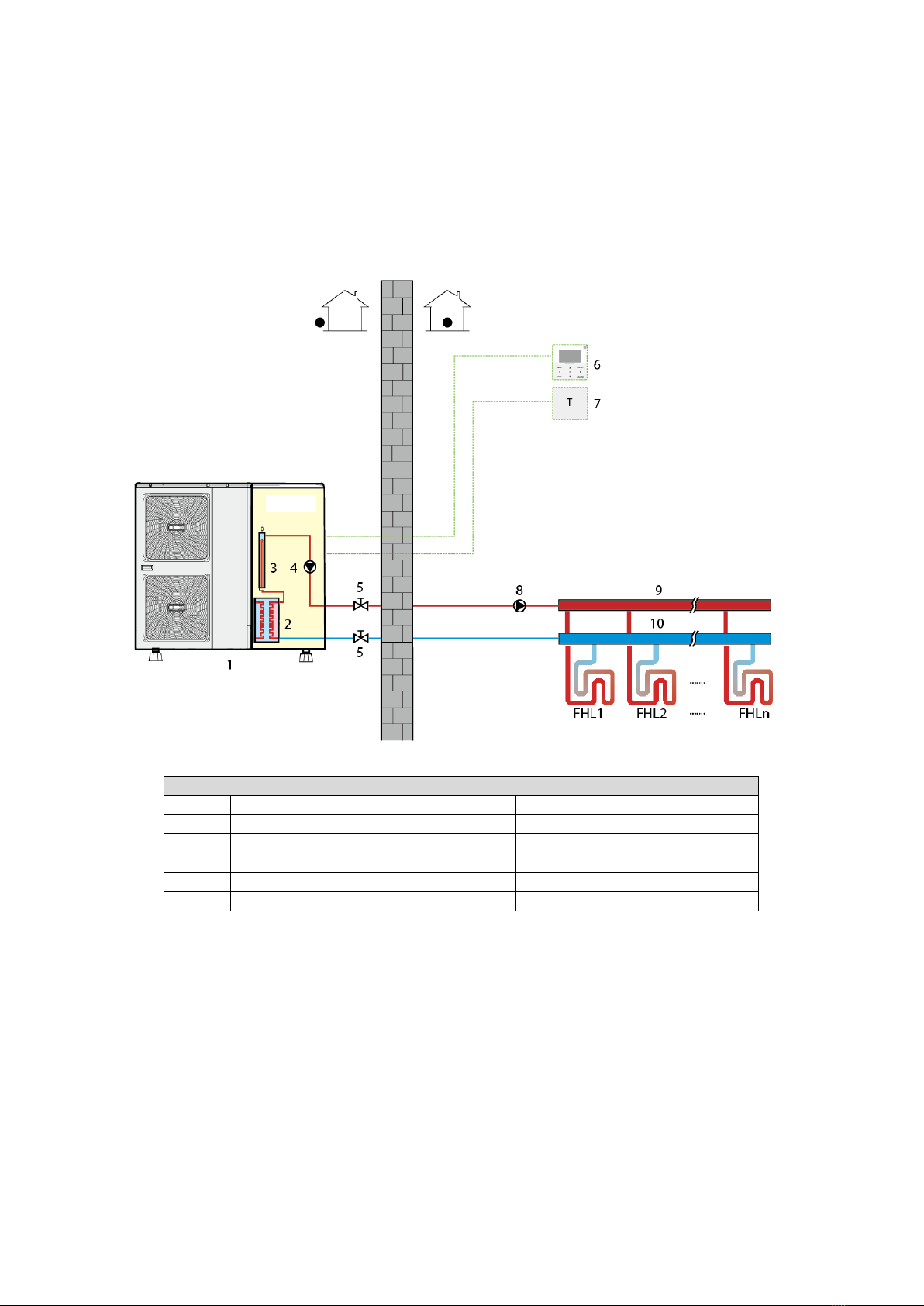
Figure 1-1.2: System configurations
5

2Unit Capacities
Table 1-2.1:M-Thermal Mono unit capacity range and unit appearances
Capacity 5kW 16kW
Model
1
(HTW-) V5WD2N8 V7WD2N8 V12WD2N8 V16WD2N8
V16WD2RN8
Appearance
Notes:
1. The presence or omission of the letter R in the model names indicates the unit’s power supply:
R: 3-phase, 380-415V, 50Hz; Omitted: 1-phase, 220-240V, 50Hz.
3Nomenclature
T16
HWV W D2 R- N8
Refrigerant
N8: R32
Power Supply
R: 3-phase, 380-415V, 50Hz
Omitted: 1-phase, 220-240V, 50Hz
Compressor and fan motor types
D2: All DC
Unit category
W: Outdoor unit
Capacity index
The capacity in kW
Inverter
HTW
12kW7kW
6

4System and Design Unit Selection
4.1 Selection Procedure
Step 1: Total heat load calculation
Calculate conditioned surface area
Select the heat emitters (type, quantity, water temperature and heat load)
Step 2: System configuration
Decide whether to include AHS and set AHS’s switching temperature
Decide whether backup electric heater is enabled or disabled
Step 3: Selection of outdoor units
Determine required total heat load on outdoor units
Set capacity safety factor
Select power supply
Provisionally select M-Thermal Mono unit capacity based on nominal
capacity
Correct capacity of the outdoor units for the following items:
Outdoor air temperature / Outdoor humidity / Water outlet temperature1 /
Altitude / Anti-freeze fluid
Is corrected M-Thermal Mono unit capacity ≥ Required total heat load on
outdoor units2
Yes No
M-Thermal Mono system
selection is complete
Select a larger model or enable
backup electric heater operation
Notes:
1. If the required water temperatures of the heat emitters are not all the same, the M-Thermal Mono’s outlet water temperature setting should be set at the
highest of the heat emitter required water temperatures. If the water outlet design temperature falls between two temperatures listed in the outdoor
unit's capacity table, calculate the corrected capacity by interpolation.
2. If the outdoor unit selection is to be based on total heating load and total cooling load, select Mono units which satisfy not only the total heating load
requirements but also the total cooling load requirements.
7

4.2 M-Thermal Leaving Water Temperature (LWT) Selection
The recommended design LTW ranges for different types of heat emitter are:
For floor heating: 30 to 35⁰C
For fan coil units: 30 to 45⁰C
For low temperature radiators: 40 to 50⁰C
4.3 Optimizing System Design
To get the most comfort with the lowest energy consumption with M-Thermal, it is important to take account of the
following considerations:
Choose heat emitters that allow the heat pump system to operate at as low a hot water temperature as possible
whilst still providing sufficient heating.
Make sure the correct weather dependency curve is selected to match the installation environment (building
structure, climate) as well as ender user’s demands.
Connecting room thermostats (field supplied) to the hydronic system helps prevent excessive space heating by
stopping the outdoor unit and circulator pump when the room temperature is above the thermostat set point.
8

5Typical Applications
5.1 Space Heating Only
The room thermostat is used as a switch. When there is a heating request from the room thermostat, the Mono unit
operates to achieve the target water temperature set on the user interface. When the room temperature reaches the
thermostat’s set temperature, the unit stops.
Figure 1-5.1: Space heating
Legend
1 Outdoor unit 7 Room thermostat (field supplied)
2 Plate heat exchanger 8 External circulator pump (field supplied)
3 Backup electric heater (customized) 9 Distributor (field supplied)
4 Internal circulator pump 10 Collector (field supplied)
5
Stop valve (field supplied)
FHL 1...n
Floor heating loops (field supplied)
6 User interface
Notes:
1. The example is just for application illustration; please confirm the exact installation method according to the
installation manual.
9

5.2 Space Heating and Domestic Hot Water
The room thermostats are not connected to the Mono unit but to a motorized valve. Each room’s temperature is regulated
by the motorized valve on its water circuit. Domestic hot water is supplied from the domestic hot water tank connected to
the Mono unit. A bypass valve is required.
Figure 1-5.2: Space heating and domestic hot water
Legend
1 Outdoor unit 10 Collector (field supplied)
2 Plate heat exchanger 11 Bypass valve (field supplied)
3 Backup electric heater (customized) 12 Domestic water tank (field supplied)
4 Internal circulator pump 13 Heat exchanger coil
5 Stop valve (field supplied) 14 Immersion heater
6
User interface
FHL 1...n
Floor heating loops (field supplied)
7
Motorized 3-way valve (field supplied)
M1...n Motorized valves (field supplied)
8
External circulator pump (field supplied)
T1…n
Room thermostats (field supplied)
9 Distributor (field supplied)
Notes:
1. The example is just for application illustration; please confirm the exact installation method according
to the installation manual.
10

5.3 Space Heating, Space Cooling and Domestic Hot Water
Floor heating loops and fan coil units are used for space heating and fan coil units are used for space cooling. Domestic hot
water is supplied from the domestic hot water tank connected to the Mono unit. The unit switches to heating or cooling
mode according to the temperature detected by the room thermostat. In space cooling mode, the 2-way valve is closed to
prevent cold water entering the floor heating loops.
Figure 1-5.3: Space heating, space cooling and domestic hot water
Legend
1
Outdoor unit
10
Two-way valve (field supplied)
2 Plate heat exchanger 11 Distributor (field supplied)
3
Backup electric heater (customized)
12
Collector (field supplied)
4 Internal circulator pump 13 Domestic water tank (field supplied)
5
Stop valve (field supplied)
14
Heat exchanger coil
6 User interface 15 Immersion heater
7 Room thermostat (field supplied) FHL 1...n Floor heating loops (field supplied)
8 Motorized 3-way valve (field supplied) FCU 1...n Fan coil units (field supplied)
9 External circulator pump (field supplied)
Notes:
1. The example is just for application illustration; please confirm the exact installation method according
to the installation manual.
11

5.4 Space Heating and Space Cooling
Floor heating loops and fan coil units are used for space heating and fan coil units are used for space cooling. The room
thermostats are not connected to the Mono unit but are connected to the fan coil units.
Figure 1-5.4: Space heating and space cooling
Legend
1 Outdoor unit 9 Distributor (field supplied)
2 Plate heat exchanger 10 Collector (field supplied)
3 Backup electric heater (customized) 11 Bypass valve (field supplied)
4 Internal circulator pump FHL 1...n Floor heating loops (field supplied)
5 Stop valve (field supplied) FCU 1...n Fan coil units (field supplied)
6 User interface M1...n Motorized valves (field supplied)
7
External circulator pump (field supplied)
T1…n
Room thermostats (field supplied)
8 Motorized 2-way valve (field supplied)
Notes:
1. The example is just for application illustration; please confirm the exact installation method according
to the installation manual.
12

5.5 Space Heating and Domestic Hot Water (Bivalent)
5.5.1 Auxiliary heat source provides space heating only
Figure 1-5.5: Space heating and domestic hot water with auxiliary heat source providing space heating only
Legend
1 Outdoor unit 9 Mixing station (field supplied)
2 Plate heat exchanger 10 Distributor (field supplied)
3 Backup electric heater (customized) 11 Collector (field supplied)
4 Internal circulator pump 12 Domestic water tank (field supplied)
5 Stop valve (field supplied) 13 Heat exchanger coil
6 User interface 14 Immersion heater
7 Motorized 3-way valve (field supplied) FHL 1...n Floor heating loops (field supplied)
8
Non-return valve (field supplied)
AHS Auxiliary heating source (field supplied)
Notes:
1. The example is just for application illustration; please confirm the exact installation method according
to the installation manual.
13

5.5.2 Auxiliary heat source provides space heating and domestic hot water
Figure 1-5.6: Space heating and domestic hot water with auxiliary heat source providing space heating and domestic hot water
Legend
1 Outdoor unit 9 Mixing station (field supplied)
2 Plate heat exchanger 10 Distributor (field supplied)
3
Backup electric heater (customized)
11
Collector (field supplied)
4 Internal circulator pump 12 Domestic water tank (field supplied)
5 Stop valve (field supplied) 13 Heat exchanger coil
6 User interface 14 Immersion heater
7
Non-return valve (field supplied)
FHL 1...n Floor heating loops (field supplied)
8 Motorized 3-way valve (field supplied) AHS Auxiliary heating source (field supplied)
Notes:
1. The example is just for application illustration; please confirm the exact installation method according
to the installation manual.
14

5.5.3 Auxiliary heat source provides additional heating
If the Mono unit’s outlet temperature is too low, the auxiliary heat source provides additional heating to raise the water
temperature to the set temperature. An additional 3-way valve is required. When the Mono unit’s outlet temperature is
too low, the 3-way valve is open and the water flows through the auxiliary heat source. When the Mono unit’s outlet
temperature is high enough, the 3-way valve is closed.
Figure 1-5.7: Space heating and domestic hot water with auxiliary heat source providing additional heating
Legend
1 Outdoor unit 9 Mixing station (field supplied)
2 Plate heat exchanger 10 Distributor (field supplied)
3 Backup electric heater (customized) 11 Collector (field supplied)
4 Internal circulator pump 12 Domestic water tank (field supplied)
5 Stop valve (field supplied) 13 Heat exchanger coil
6 User interface 14 Immersion heater
7 Non-return valve (field supplied)
FHL 1...n Floor heating loops (field supplied)
8
Motorized 3-way valve (field supplied)
AHS Auxiliary heating source (field supplied)
Notes:
1. The example is just for application illustration; please confirm the exact installation method according to
the installation manual.
15

5.6 Space Heating Through Floor Heating Loops and Fan Coil Units
Dual setpoint function application with or without two thermostat connect to the outdoor unit. The floor heating loops
and fan coil units require different operating water temperatures. To achieve these two set points, a mixing station is
required. Room thermostats for each zone are optional.
Figure 1-5.8: Space heating through floor heating loops and fan coil units
Legend
1 Outdoor unit 10 Distributor (field supplied)
2 Plate heat exchanger 11 Collector (field supplied)
3 Backup electric heater (customized) 12 Bypass valve (field supplied)
4 Internal circulator pump FHL 1...n Floor heating loops (field supplied)
5 Stop valve (field supplied) FCU 1...n Fan coil units (field supplied)
6
User interface
M1...n
Motorized valves (field supplied)
7 External circulator pump (field supplied)
T1…n Room thermostats (field supplied)
8
Motorized 2-way valve (field supplied)
TA
Zone A thermostat (field supplied)
9 Mixing station (field supplied)
TB
Zone B thermostat (field supplied)
Notes:
1. The example is just for application illustration; please confirm the exact installation method according
to the installation manual.
16

5.7 Space Heating and Domestic Hot Water Heating with a solar energy kit
Space heating application and domestic hot water heating with a solar energy kit connected to the system; space heating
provided by heat pump, domestic hot water heating is provided by heat pump and solar energy kit.
Figure 1-5.9: Space Heating and Domestic Hot Water Heating with a solar energy kit
Legend
1 Outdoor unit 10 Immersion heater
2 Plate heat exchanger 11 Motorized 3-way valve (field)
3 Backup electric heater (customized) 12 Two-way valve (field supplied)
4 Internal circulator pump 13 Distributor (field supplied)
5 Stop valve (field supplied) 14 Collector (field supplied)
6 User interface 15 Bypass valve (field supplied)
7 External circulator pump (field supplied)
FHL 1...n Floor heating loops (field supplied)
8
Domestic hot water tank (field supplied)
9 Heat exchanger coil
Notes:
2. The example is just for application illustration; please confirm the exact installation method according
to the installation manual.
17


Part 2
Engineering Data
1 Specifications ........................................................................................... 20
2 Dimensions and Center of Gravity ............................................................ 26
3 Piping Diagrams ....................................................................................... 28
4 Wiring Diagrams....................................................................................... 29
5 Capacity Tables......................................................................................... 35
6 Operating Limits....................................................................................... 47
7 Hydronic Performance.............................................................................. 48
8 Sound Levels ............................................................................................ 50
9 Accessories .............................................................................................. 56
19
This manual suits for next models
5
Table of contents
Other HTW Air Conditioner manuals

HTW
HTW HTWS026IX21DPLUS User manual

HTW
HTW V10 User manual

HTW
HTW P36 User manual

HTW
HTW PURE LIGHT UV HTWS026PLUV User manual

HTW
HTW WAVE HTW-VE-035V1 Service manual

HTW
HTW IX21D3 User manual

HTW
HTW P26 Series User manual

HTW
HTW IX43 R32 User manual

HTW
HTW ALP User manual

HTW
HTW HTWS026IX80SR32-I Service manual