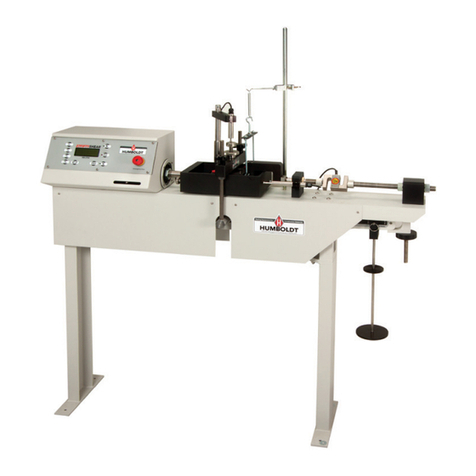
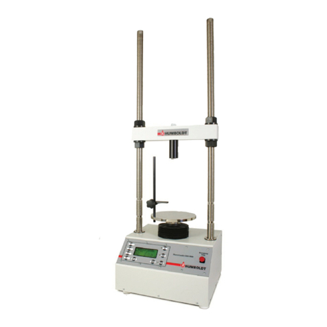
Humboldt HM-2850.3F User manual

product manual
03.18
HM-2850.3F
Humboldt
Multi-Speed Load Frame

Application
The HM-2850 Multi-speed Load Frame is designed for those who
want a high-quality, but simple, multi-purpose load frame without
built-in data acquisition capabilities. The HM-2850 is ideal for
applications where the operator is either not concerned with data
acquisition; or, already has or is planning to construct their own
data acquisition system. With its large 7" color, touchscreen, the
HM-2850 provides the operator with the ability to precisely select
any speed with four decimal accuracy within the machine’s speed
range.
The HM-2850 features a quiet, direct drive stepper motor that
provides a range of loading speeds from 0.00001 to 2.00000 in/
min (0.00001 to 50.80000mm/min.). This speed range is more than
adequate for the majority of standard soil tests.
The HM-2850 also incorporates a separate, dedicated control to
accommodate 2.00000 in/min (50.80000mm). for use in Marshall
and TSR Testing, as
well as a rapid travel speed of 2.25 in/min for moving the platen
into position quickly. Speeds are controlled through the use of edit
keys and the digital display.
Product Use
This product is intended for use only in accordance with the
directions and specifications contained in this User Guide. The
HM-2800 Multi-speed Load Frame has been designed for testing
that complies with ASTM D1883, D2850, D2166, D4767, D5581
and D6927 and AASHTO T193, T296, T297, T208, T245, T246, as
well as other applicable International standards.
Features include:
• 8" plated platen provides roomy, stable base
for test equipment
• 7" color, touchscreen
• Test speeds adjustable from 0.00001 to 2.00000 in/min
(0.00001 to 50.80000mm/min.) via touchscreen
• User selectable unit change from keyboard between U.S.
Standard and Metric units.
1
Machine Specifications
Covers: CBR, UU, CU, CD, UC, Marshall and Hveem Tests.
ASTM: D1883, D2850, D2166, D4767, D5581 and D6927
AASHTO: T193, T296, T297, T208, T245, and T246;
BS 1377: Part 4: 1990, BS 1377: Part 7: 1990, BS 1377: Part 8:
1990, BS 598: Part 107
General Warnings
Safety Warnings
Operators should take care to operate this machine under the
maximum load restrictions. The machine is programmed at
the factory to provide safety shutdown if the upper or lower
maximum travel is exceeded as well as if the upper instrument
calibration is exceeded.
Electrical Warnings
Typically, there is no reason for the operator to open the
machine. However, if the customer’s engineers attempt to
change settings to the circuit board connected to the back panel,
the machine must always be unplugged before this operation.
Unplugging the internal connection to the back panel circuit
board while the machine is under power will result in permanent
damage to the circuit board.
2
Specifications
Load capacity 11000 lbf (50kN)
Speed range 0 - 2.00000 in/min.
0 - 50.80000 mm/min.
Platen Size 8" (203mm)
Platen Travel 4" (100mm)
Clearance, vertical 40" (1000mm) Max
Clearance, horiz. 11" (279mm)
Dimensions (l x w x h). 17 x 22 x 51 inch
(432 x 559 x 1295mm)
Voltage 110/220V 50/60Hz. 5.0 amps

IMPORTANT NOTICE
The information contained herein is supplied without
representation or warranty of any kind. Humboldt Mfg. Co.
therefore assumes no responsibility and shall have no liability,
consequential or otherwise, of any kind arising from the use of the
described equipment contained in this manual.
Updated products
The manufacturer reserves the right to change or modify product
design or construction without prior notice and without incurring
any obligation to make such changes and modifications on
products previously or subsequently sold.
Fitness for application
The manufacturer makes no recommendations or claims
regarding fitness for applications other than the specific tests as
defined in this User Guide.
Installation and Set-up
Unpacking
During your inspection, make certain that the contents of your
shipment match the documentation provided by your packing
list. Accessories that are part of your order may have been
packed with or installed onto the HM-2850, so make sure they are
accounted for and match the packing list.
Listed below are those items included with an HM-2850 Multi-
Speed Load Frame:
Multi-Speed Load Frame— HM-2850.3F
Includes:
SHH04—3/4-16 Bolt x 3-1/2 inch long
WF04—Washer for SHH04 Bolt
HM-000352—AC Power Cord
3

Electrical Connections
Place unit on a flat smooth surface and use leveling feet (supplied) and
a bubble level to ensure that the unit is level side-to-side and back-to-
front.
Electrical Connections
The HM-2850 arrives ready for operation. Attach the supplied IEC
electrical cord to the machine and plug into a standard wall receptacle
for use in the United States.
Power Cord:
Your Multi-use Test Machine is fitted with a molded vinyl grounding
plug. The cord is made of three conductors either
(American color coding).
Green Ground (Earth)
White Cold (Neutral)
Black Hot (Live)
or
(International color coding).
Green/Yellow Ground (Earth)
Blue Cold (Neutral)
Brown Hot (Live)
Fuses:
The HM-2850 uses (2) 5x20mm, slo-blow fuses in the IEC power entry
module at the right rear of the machine. The replacement part number
for these fuses is H-1322.13.
4

Operation
Control Panel
An On-Off rocker switch on the back right side of the machine is
the power switch. The control panel is situated on the front left
hand side of the machine base. A 7" touch-screen displays the
speed and units in either in/min or mm/min. A touch-screen en-
ables setting the speeds and units and control of machine travel.
Speed Selection
On the control panel, pressing Motor Speed causes the display to
display the motor speed keypad where you can enter the desired
speed.
Speed Units Selection
Press the unit to select in/min or mm/min.
Running a Test
After selecting the desired speed and positioning the sample, ini-
tiate a test by pressing the Up Arrow. Upon conclusion of the test
press the Stop Test key. See Page 7 for a chart of common tests
and test speeds.
Rapid Travel
Pressing and holding down either the up or down arrows allows
travel at slightly over 2.25 in/min in the direction chosen and
releasing either key will stop the travel.
1
5

Maximum Travel
A redundant limit switch prevents over travel in the up or down
directions by stopping the machine automatically. The maximum
travel of the platen is 4.00 inches (100mm).
Load Ring
When a load ring is used it can be attached directly to the cross-beam
using the 3/4-16 x 3” long bolt.
Maximum Load
This Compression and Testing Machine is rated a 11,000 lbf (50kN).
Accuracy of Platen Speeds
The indicated speeds are based on zero load conditions and will be
maintained within +/- 5%. The actual motor speed will be maintained
to +/- 1%. These are not closing gap speeds.
The speeds used in the various test are, in fact, the closing gap speed,
i.e., the distance between the cross-beam and the platen. These
closing gap speeds will be dependent on the stiffness of the sample
being tested and the compressibility of any load measuring device
(such as the load ring). At high loads, some machine stretch may occur.
The test speeds used should, therefore, take into account these factors.
Maintenance
Both the jack unit and the gearbox are packed with grease and do
not normally require further attention. The machine can generally be
maintained by keeping it clean, and if adjusting the crosshead beam,
lightly oiling the exposed threads.
6

Test
Description Standards Speed
in/min. Tolerance Comments
CBR, 1mm BS 1377, Clause 7.4.2.2 .039
(1mm/min.) ± 20% ie.
.2 mm/min.
UU Triaxial
Unconsolidated
Undrained, 1.4"
ASTM D2850
Para. 5.1 & 7.5
AASHTO T208
1% min. plastic,
.3% min. brittle —5% constant rate,
strain control Cohesive soils;
no ripples in a
glass of water
UU Triaxial
Unconsolidated
Undrained, 1"
BS 1377, Part 7 .3% min.
Unconfined
Cohesive Soil ASTM D2166
Para. 7.1 1/2 to 2% min. Strain Controlled Clay or
Cemented Soils
UC Consolidated
Undrained, 1.4" ASTM D4767
Para. 5.2 .028 or formula
in Para. 8.4.2 ±1% Cohesive
Plastic Soils
Marshall/TSR ASTM D6927 & 5581;
AASHTO T245 2" ±.15
or 7.5%
Mold Soil Cement ASTM D1633 Approx. .05 Continuous w/o shock
CBR/LBR
Hveem &
Soil Cement
ASTM D1883, D4429
(field) AASHTO T193 Approx. .05
no pulses Continuous
run at idle w/o shock
UU Unconsolidated
Undrained quick triaxial, 1.4" ASTM D2850 .008 ±5% Brittle material
UU Unconsolidated
Undrained quick triaxial, 2.8" ASTM D2850 .017 ±5% Brittle material
UC Unconsolidated
Undrained triaxial for
cohesive soil
ASTM D4767
Para. 5.2 .056 or formula
in Para. 8.4.2 ±1% Cohesive soils
w/plasticity
Common Speeds for Specimen Testing
7

Typical Test Setups for the HM-2850
The charts below list the parts necessary to perform these standard tests.
CU/UU Triaxial Setup with HM-2850
Components Item
Load
50kN (11240 lbf) capacity HM-2850.3F
Strain
Load ring 2,200 lbf (10 kN)
H-4454.020
Dial gauge 2.0" travel,
0.001" divisions) H-4463
Pore pressure transducer HM-4170
Ball seat adapter HM-200387
Single channel readout
(choose)
HM-2350
HM-2350.4F
NEXT software basic,
user defined included
Pressure
Pressure distribution panel for
CU triaxial (choose)
HM-4150.3F
HM-4150M.3F
Pressure distribution panel for
UU triaxial (choose)
HM-4140.3F
HM-4140M.3F
De-airing system HM-4187A.3F
Vacuum pump (choose) H-1763A
H-1763A.4F
Triaxial Cell (choose 1 below)
3"/ 75mm dia. capacity HM-4199B
4"/ 100mm dia. capacity HM-4199B-4
Top Cap/ Base Pedestal Set
(specify specimen size) HM-4199.XX

9
Part Numbers ending in .XX require a size code to be entered referring to
the sample size to be tested. For Triaxial samples, sizes are: .14 = 1.4";
.15 = 1.5"; .20 = 2.0"; .25 = 2.5"; .28 = 28"; .30 = 3.0".40 = 4.0";
.35 = 35mm; .38 = 38mm; .50 = 50mm; .70 = 70mm, and .100 = 100mm.
Typical Test Setups for the HM-2850 (cont.)
Typical Soil Cement Setup
Components
Load
50kN (11240 lbf) capacity HM-2850.3F
Upper swivel platen HM-2003E
Strain
Load ring 5,000 lbf (25 kN)
H-4454.050
Unconfined Compression Setup with HM-2850
Components
Load
50kN (11240 lbf) capacity HM-2850.3F
Upper unconfined platen HM-2002
Displacement
indicator platform HM-3000.10.2
Displacement indicator rod HM-3000.10.1
Load ring 500 lbf (2.5 kN)
H-4454.005
Dial gauge 2.0" travel
0.001" divisions H-4463
Typical Triaxial Sample Prep Items
Components
Part # Qty. Description
HM-4180.XX
1
Membranes, 12/pk
HM-4181.XX
1
Membrane Stretcher
HM-4182.XX
1
O-Rings, 12/pk
HM-4184.XX
2
Porous Stone
HM-4187E
1
De-Airing Tank, 6 Liter, 110V
HM-3847.XX
1
Split Miter Box
HM-4189.XX
1
Filter Paper, 100/pk
HM-4189FS
1
Filter Strips 5 x 150mm 100/pk

10

www.humboldtmfg.com
HUMBOLDT
Testing Equipment for Construction Materials
Humboldt Mfg. Co.
3801 North 25th Avenue
Schiller Park, Illinois 60176 U.S.A.
U.S.A. Toll Free: 1.800.544.7220
Voice: 1.708.456.6300
Fax: 1.708.456.0137
Email: [email protected]
Warranty
Humboldt Mfg. Co. warrants its products to be free from defects in material or
workmanship. The exclusive remedy for this warranty is Humboldt Mfg. Co.,
factory replacement of any part or parts of such product, for the warranty of this
product please refer to Humboldt Mfg. Co. catalog on Terms and Conditions
of Sale. The purchaser is responsible for the transportation charges. Humboldt
Mfg. Co. shall not be responsible under this warranty if the goods have been
improperly maintained, installed, operated or the goods have been altered or
modified so as to adversely affect the operation, use performance or durability
or so as to change their intended use. The Humboldt Mfg. Co. liability under
the warranty contained in this clause is limited to the repair or replacement of
defective goods and making good, defective workmanship.
Table of contents
Other Humboldt Test Equipment manuals

Humboldt
Humboldt H-4374 User manual

Humboldt
Humboldt H-4212MH User manual

Humboldt
Humboldt ConMatic IMC User manual

Humboldt
Humboldt HM-5760.3F User manual

Humboldt
Humboldt HM-5040.3F User manual

Humboldt
Humboldt Digital MasterLoader HM-3000.3F User manual

Humboldt
Humboldt H-4165 User manual

Humboldt
Humboldt HM-5030 User manual

Humboldt
Humboldt Speedy 2000 H-4968 User manual

Humboldt
Humboldt HM-5470.3F ConMatic IPC User manual