Humzor NEXZSYS NS706 User manual

1
NEXZSYS Windows Products
User's Manual
Trademarks
HUMZOR®, NEXZSYS®, NEXZLINK®, NEXZSCAN®, and NEXZSYS® are trademarks of
Shenzhen Hanzhi Technology Co., Ltd., registered in China, the United States and other countries. All other
marks are trademarks or registered trademarks of their respective holders.
Copyright Information
No part of this manual may be reproduced, stored in a retrieval system or transmitted, in any form or by
any means, electronic, mechanical, photocopying, recording, or otherwise without the prior written permission
of HUMZOR.
Disclaimer of Warranties and Limitation of Liabilities
All information, specifications and illustrations in this manual are based on the latest information
available at the time of printing.
HUMZOR reserves the right to make changes at any time without notice. While information of this
manual has been carefully checked for accuracy, no guarantee is given for the completeness and correctness of
the contents, including but not limited to the product specifications, functions, and illustrations.
HUMZOR will not be liable for any direct, special, incidental, indirect damages or any economic
consequential damages (including lost profits).
IMPORTANT
Before operating or maintaining this unit, please read this manual carefully, paying extra attention to the
safety warnings and precautions.
For Services and Support
www.humzor.com
www.humzor.cn
service@humzor.com
info@humzor.com
For details, please refer to the Service Procedures in this manual.

2
Safety Information
For your own safety and the safety of others, and to prevent damage to the device and vehicles upon
which it is used, it is important that the safety instructions presented throughout this manual be read and
understood by all persons operating or coming into contact with the device.
There are various procedures, techniques, tools, and parts for servicing vehicles, as well as in the skill of
the person doing the work. Because of the vast number of test applications and variations in the products that
can be tested with this equipment, we cannot possibly anticipate or provide advice or safety messages to cover
every circumstance. It is the automotive technician's responsibility to be knowledgeable of the system being
tested. It is crucial to use proper service methods and test procedures. It is essential to perform tests in an
appropriate and acceptable manner that does not endanger your safety, the safety of others in the work area, the
device being used, or the vehicle being tested.
Before using the device, always refer to and follow the safety messages and applicable test procedures
provided by the manufacturer of the vehicle or equipment being tested. Use the device only as described in this
manual. Read, understand, and follow all safety messages and instructions in this manual.
Safety Messages
Safety messages are provided to help prevent personal injury and equipment damage. All safety messages
are introduced by a signal word indicating the hazard level.
DANGER
Indicates an imminently hazardous situation which, if not avoided, will result in death or serious injury to
the operator or to bystanders.
WARNING
Indicates a potentially hazardous situation which, if not avoided, could result in death or serious injury to
the operator or to bystanders.
Safety Warnings
⚫Always perform automotive testing in a safe environment.
⚫Wear safety eye protection that meets ANSI standards.
⚫Keep clothing, hair, hands, tools, test equipment, etc. away from all moving or hot engine parts.
⚫Operate the vehicle in a well-ventilated work area, for exhaust gases are poisonous.
⚫Put the transmission in PARK (for automatic transmission) or NEUTRAL (for manual transmission) and
make sure the parking brake is engaged.
⚫Put blocks in front of the drive wheels and never leave the vehicle unattended while testing.
⚫Be extra cautious when working around the ignition coil, distributor cap, ignition wires and spark plugs.
These components create hazardous voltages when the engine is running.
⚫Keep a fire extinguisher suitable for gasoline, chemical, and electrical fires nearby.

3
⚫Do not connect or disconnect any test equipment while the ignition is on or the engine is running.
⚫Keep the test equipment dry, clean, free from oil, water or grease. Use a mild detergent on a clean cloth to
clean the outside of the equipment as necessary.
⚫Do not drive the vehicle and operate the test equipment at the same time. Any distraction may cause an
accident.
⚫Refer to the service manual for the vehicle being serviced and adhere to all diagnostic procedures and
precautions. Failure to do so may result in personal injury or damage to the test equipment.
⚫To avoid damaging the test equipment or generating false data, make sure the vehicle battery is fully
charged and the connection to the vehicle DLC is clean and secure.
⚫Do not place the test equipment on the distributor of the vehicle. Strong electro-magnetic interference can
damage the equipment.

4
CONTENTS
1USING THIS MANUAL ........................................................................................................... 5
1.1 CONVENTIONS..................................................................................................................................... 5
2GENERAL INTRODUCTION.................................................................................................. 6
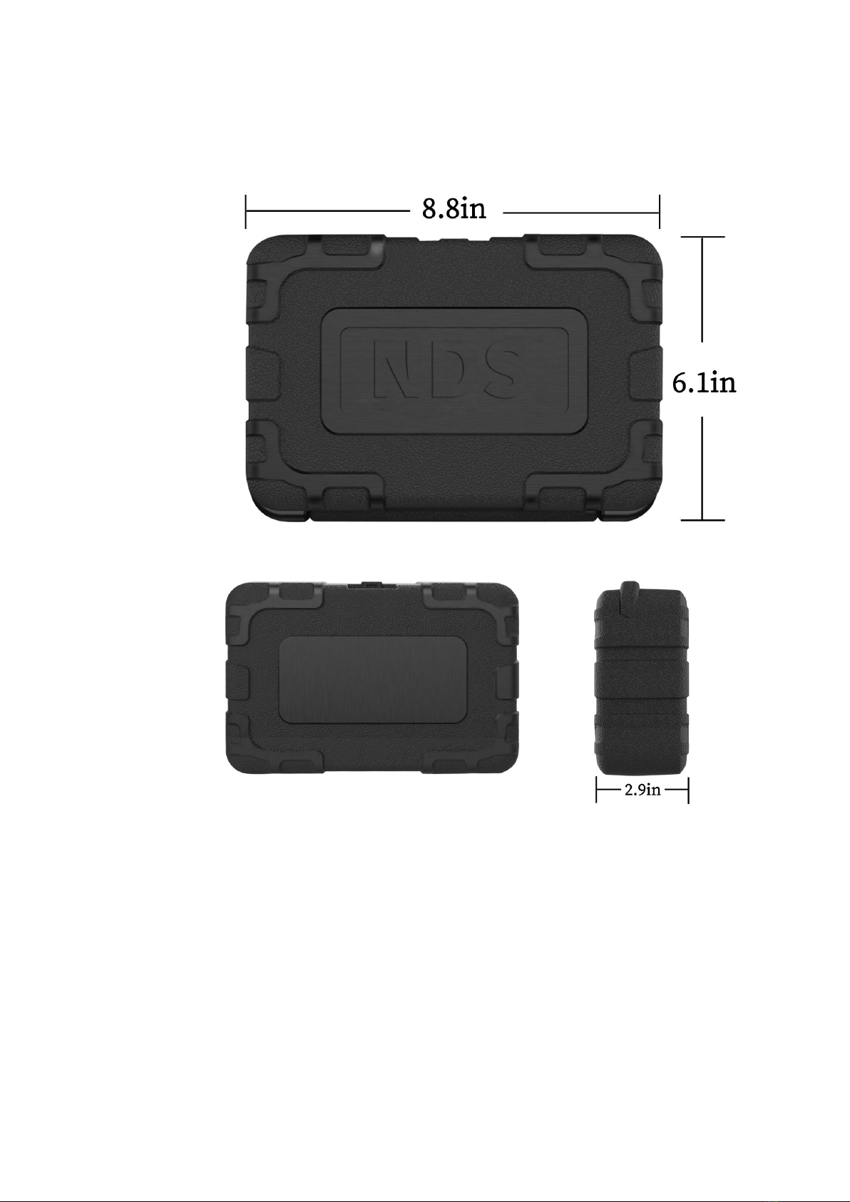
2.1 ACCESSORIES AND PACKAGE.............................................................................................................. 6
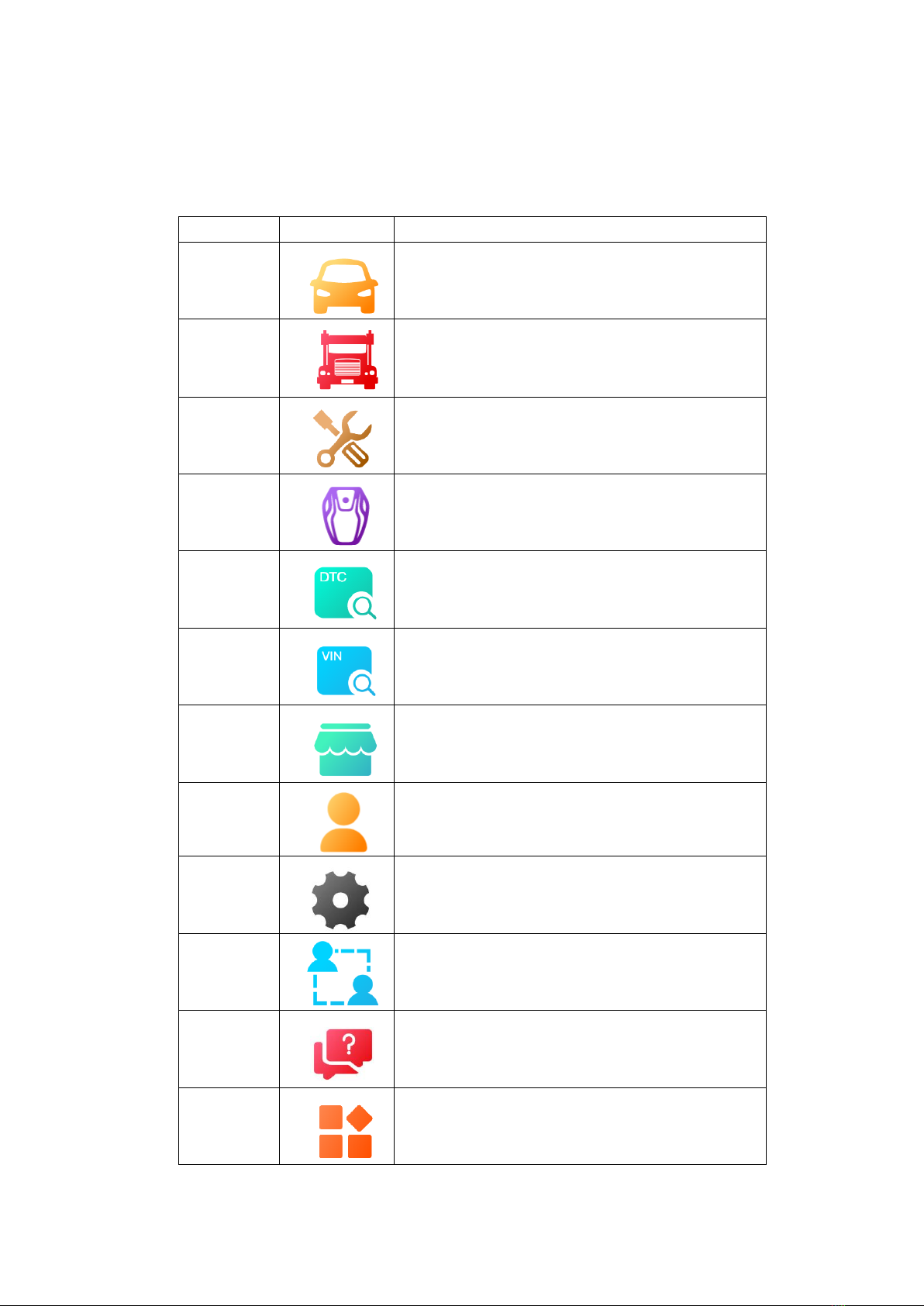
2.3 SOFTWARE OVERVIEW ........................................................................................................................ 8
3GETTING STARTED............................................................................................................... 9
3.1 START UP............................................................................................................................................ 9
3.2 SHUT DOWN...................................................................................................................................... 11
4SOFTWARE INSTALLATION AND RUNNING.................................................................... 11
4.1 SOFTWARE INSTALLATION ................................................................................................................ 11
4.2 SOFTWARE RUNNING ........................................................................................................................ 12
5PRODUCT REGISTRATION AND LOGIN........................................................................... 12
5.1 USER REGISTRATION......................................................................................................................... 12
5.2 LOGIN................................................................................................................................................ 14
5.3 WIFI CONNECTION ........................................................................................................................... 18
6DIAGNOSTICS ...................................................................................................................... 19
6.1 ESTABLISH VEHICLE COMMUNICATION............................................................................................ 19
6.2 PROTOCOL SUPPORTED ..................................................................................................................... 19
6.3 GETTING STARTED ............................................................................................................................ 20
7SPECIAL FUNCTION............................................................................................................ 30
8KEY PROGRAMMING ......................................................................................................... 33
9APP STORE............................................................................................................................ 36
9.1 VEHICLE............................................................................................................................................ 36
9.2 SPECIAL FUNCTION ........................................................................................................................... 38
9.3 IMMO............................................................................................................................................... 39
10 DTC QUERY....................................................................................................................... 40
11 PERSONAL............................................................................................................................ 40
11.1 EDITING PERSONAL INFORMATION ................................................................................................. 40
11.2 UPGRADE ........................................................................................................................................ 41
11.3 PRODUCT SERIAL NUMBER SWITCH ............................................................................................... 41
11.4 LOG OUT ......................................................................................................................................... 42
11.5 REMOTE ASSISTANCE...................................................................................................................... 42
12 FEEDBACK ........................................................................................................................ 42
14 OTHER ..................................................................................................................................... 48
14.1 DATA PLAYBACK ............................................................................................................................. 48
14.2 DATA MANAGEMENT ...................................................................................................................... 48
15 SCREENSHOT...................................................................................................................................... 50

5
1Using This Manual
This manual contains device usage instructions.
Some illustrations shown in this manual may contain modules and optional equipment that are not
included in your system.
1.1 Conventions
The following conventions are used.
1.1.1 Bold Text
Bold text is used to highlight selectable items such as buttons and menu options.
Example:
⚫ Tap NEXT.
1.1.2 Notes and Important Messages
A NOTE provides helpful information such as additional explanations, tips, and comments.
The IMPORTANT indicates a situation that if not avoided may result in damage to the tablet or vehicle.
1.1.3 Illustrations
Illustrations used in this manual are samples, and the actual testing screen may vary for each vehicle
being tested. Observe the menu titles and on-screen instructions to make correct option selection.
1.1.4 Procedures
An arrow icon indicates a procedure.
Example:
➢ To use the Feedback:
1. Tap the Feedback button. The customer can feedback the software bug to engineer.
2. Select the vehicle brand and type.
3. Describe software problem found or customer requirement in the edit box. Or select the image for
the tablet.
4. Tap the NEXT to send the feedback to engineer.
5. Tap the Back or Home button to exit the feedback application.

6
2General Introduction
The NEXZSYS NS706/NS806/NS906 is a multi-platform diagnostic solution in PC or laptop, a
NEXZ-BOX communication and diagnostic measurement unit and an on-tool and cloud-based repair
instructions and expert advice. As an intelligent diagnostic and information system, NEXZSYS
NS706/NS806/NS906 not only displays the relevant repairs gathered from experienced industry experts, but
provides step-by-step guidance to ensure the repair is done correctly and efficiently.
There are two main components to the NEXZSYS NS706/NS806/NS906 system:
⚫ NEXZSYS APP – the central processor and monitor for the system.
⚫ NEXZ-BOX VCCI - Vehicle Communication and Check Interface.
This manual describes the construction and operation of these devices and how they work together to
deliver diagnostic solutions.
2.1 Accessories and Package
2.1.1 Accessories
Figure 2-1 NEXZSYS Accessories View

7
2.1.2 Package
Figure 2-2 NEXZSYS Package View
2.2 VCCI – Vehicle Communication and Check Interface

8
Figure 2-3 NEXZSYS VCCI Top View
2.3 Software Overview
2.3.1 Overview
NEXZSYS is a tool-based APP which focus on car diagnosis, reset, key programming and other
maintenance functions in windows. It is connected to the vehicle through a specific Wi-Fi device. The car
owner or maintenance worker can learn the basic information and the existed faults of the vehicle in real time
through the software, etc., making vehicle maintenance become more convenient.
2.3.2 Features
① Wide coverage of vehicle brands of Asia, Europe and America..., free download.
② Support full-system electronic control diagnosis, quickly scan the conditions of all electronic control
systems of the car, and then generate professional diagnosis reports.
③ Special customization, special functions are supported, such as Oil Reset, TPMS, EPB, DPF, SAS,

9
CVT, Injector Coding, and etc.
④ Support online DTC Query, Remote Assistance, One-click to Feedback, Screenshot, Screen Recording,
and Upgrade.
2.3.3 Performance
The software is easy to operate and reliable, guarantees the authenticity and security of information.
3Getting Started
Make sure the computer has sufficient power or is connected to the external power supply.
3.1 Start Up
The system boots up and shows the main interface with 3 entry functional area:
Figure 3-1 Application Menu
1. Application Buttons - Diagnose and application functions selection.
2. Locator and Navigation Buttons – Quickly boot to diagnose function or return windows system home.
3. Status Icons - Display system and communication signals.

10
3.1.1 Application Buttons
The table below briefly describes each of the applications in the NEXZSYS system.
Table 3-1 Applications
Name
Button
Description
Car
Diagnostics
Accesses the unit's car diagnostics functions.
Heavy-duty
Diagnostics
Accesses the unit's Heavy-duty diagnostics functions.
Special
Function
Accesses special functions menu
IMMO Key
Accesses Key programming and IMMO Reset menu
DTC Query
Accesses the DTC Query functions.
VIN Query
Accesses the VIN Query functions.
APP Store
Accesses system function download menu.
Personal
Accesses saved consumer information and change data live
unit, upgrade NEXZSYS system application, logo in/out
system and switch/add product.
Settings
Accesses the system settings menu.
Remote
Assistance
Configures your unit to receive remote support
using the TeamViewer application.
Feedback
Collect the customer requirement or question to engineer team.
Others
Accesses valuable application Data Management, data
playback and so on.

11
3.1.2 Locator and Navigation Buttons
Operations of the Navigation buttons at the bottom of the screen are described in the table below:
Table 3-2 Locator and Navigation buttons
Name
Button
Description
Persoanl
Accesses saved consumer information.
Settings
Accesses the system settings menu.
Camera
Take a screenshot and save the picture.
Wi-Fi
Displays the connection status of the tablet to VCCI.
3.1.3 System Status Icons
NEXZSYS APP has a fully functional Windows with the standard windows operating system status icons.
Refer to windows documentation for additional information.
3.2 Shut Down
All vehicle communications should be terminated before shutting down the PC. A warning message
displays if a shutdown is attempted while the PC is communicating with the vehicle.
Forcing a shut down while the PC is communicating with the vehicle may lead to ECU errors on some
vehicles.
Please exit the Diagnostics application before shutting off the PC.
4Software Installation and Running
4.1 Software Installation
The software comes with NEXZSYS USB within the package box.

12
4.2 Software Running
The user clicks on the NEXZSYS icon to enter the system.
Figure 4-1 Sample Application Home
5Product Registration and Login
5.1 User Registration
When you access the "NEXZSYS" application for the first time, you need to follow the steps below to
register:
1. Click the "NEXZSYS" icon on the desktop to open the application.
2. On the Login interface, click the "Register" button to enter the registration interface.
3. Enter your mailbox or mobile phone number in the "Email" column.
4. Click the "GET CAPTCHA" button to get your captcha.
5. Enter the captcha you obtained in the "CAPTCHA" column.
6. Set up your password in the "Enter password" field, and enter your password again in the "Confirm
Password" field.
7. Click the "->" button at the bottom, once your email account, captcha, and password format are
entered correctly, then the registration will be successful.

13
Figure 5-1 Sample Login and Registration Interface
Figure 5-2 Sample Registration Interface

14
5.2 Login
Users who have registered can log in through the following steps:
1. Click the "NEXZSYS" icon on the desktop to open the application.
2. On the Login registration interface, enter the email or mobile number you need to log in in the "E-mail"
column.
3. Enter your login password in the "Password" column.
4. Click the icon on the right side of the "Password" column to encrypt your password, and the
icon becomes . Click the icon on the right side of the "Password" column to display your
password, and the icon will turn into .
5. Click the "Login" button. Once you have entered the correct account and password, then login will be
successful and the system will guide you to the serial number binding and selection interface.
5.2.1 Change Password
If you forget your password or need to set a new password, you can follow the steps below:
1. Click the "NEXZSYS" icon on the desktop to open the application.
2. On the login and registration interface, click the "Forget Password?" button to enter the password reset
interface.
3. Enter your login account in the "Account" field.
4. Click the "GET CAPTCHA" button to get your captcha.
5. Enter the captcha you obtained in the "CAPTCHA" field.
6. Enter your new password in the "Input the new password" field, and enter your new password again in
the "Input the Password again" field.
7. Click the "->" button at the bottom, once your account, captcha, and password format are entered
correctly, then the new password is set successfully.

15
Figure 5-3 Sample Password Reset Interface
5.2.2 Serial Number Binding
After the user logs in successfully, it comes to the serial number binding interface. Users can add, delete,
and select products here.
Figure 5-4 Sample Binding Serial Number Interface

16
5.2.3 Product Binding
1. Manually input
a. Click the "Add a new product" button and the "Binding serial number" interface will pop up.
b. Enter the serial number (S/N) of the device you purchased in the "Serial number" field, and enter the
Activation code of the device in the "activation code" field.
c. Click the "Okay" button. If the serial number and activation code you entered are consistent with the
serial number and activation code of the purchased device, the binding is successful.
Figure 5-5 Sample Binding Serial Number Interface
2. Scan code to binding
A. Click the "Add a new product" button and the "Binding serial number" interface will pop up.
B. Click the scan code icon on the right side of the "activation code" column to open the scan interface.
C. Align the QR code of the device you purchased, and if the code is scanned successfully, the serial
number will be automatically bound.
5.2.4 Product Deletion
If you need to delete the serial number, swipe your finger to the left on the row of the serial number that
needs to be deleted, and click the "Delete" button that slides out to successfully delete the serial number.

17
Figure 5-6 Sample Delete Serial Number
5.2.5 Product Selection
1. Click the product serial number you need to enter, and the icon on the right becomes .
2. Click the "Next step" button and the system will guide you to the main interface of "HUMZOR".
5.2.6 Enable Location Permission
IMPORTANT
Windows7 or above, the tablet need to get tablet address information. If your tablet device does not have
permission to allow get your location, please follow the steps below to turn it on.

18
Figure 5-7 Sample Location Permission Prompt Box
5.3 WIFI Connection
After you select the product serial number to enter the "HUMZOR" main interface, you can view and
connect to the VCI device with the corresponding serial number you have purchased through the following
steps:
1. Insert the VCI of the HUMZOR NEXZSYS product you purchased tightly into the OBD port. At this
time, the WIFI icon on the top right side is.
2. Turn on the ignition switch, the NEXZSYS application will automatically scan and recognize the VCI
device, and establish a WIFI connection. At this time, the WIFI icon on the top right-side changes to , and
the WIFI connection is successful.
3. If the NEXZSYS application cannot automatically connect to your VCI device, or the device fails to
connect, please click the icon button on the top right to reconnect, or check whether the VCI is well
connected to the car’s OBD port.
Figure 5-8 NEXZSYS Not Connected Figure 5-9 NEXZSYS Connected

19
6Diagnostics
The Diagnostics application can access the electronic control module of multiple vehicle control systems,
including but not limited to the engine, transmission, antilock brake system (ABS) and airbag system (SRS).
6.1 Establish Vehicle Communication
The diagnostics operations require connecting the PC to the test vehicle through the VCCI device using
the Main Cable. (Use the applicable OBDI-type adapter if needed). To establish proper vehicle communication
to the PC, you need to perform the following steps:
1. Connect the VCI device to the vehicle's DLC for both communication and power source.
2. Connect the VCI device to the PC via BT auto-pairing, Wi-Fi or USB connection.
3. When the above steps are completed, check the VCI navigation button at the bottom bar on the screen.
If a blue BT, Wi-Fi or USB icon displays at the upper right corner, the NEXZSYS Diagnostic Platform is ready
to start vehicle diagnosis.
6.2 Protocol Supported
The following protocols are included:
High Speed CAN - offers baud rates from 40 Kbit/s to 1 Mbit/sec, depending on cable length. This is
the most popular standard for the physical layer, since it allows for simple cable connection between devices.
High speed CAN networks are terminated with 120 ohm resistors on each end of the network.
Low Speed CAN - offers baud rates from 40 Kbit/s to 125 Kbits/sec. This standard allows CAN bus
communication to continue in case of a wiring failure on the CAN bus lines. In low speed CAN networks, each
device has its own termination.
Single CAN - offers baud rates up to 33.3 Kbit/s (up to 88.3 Kbit/s for high-speed mode)
J1939 CAN - is used in the commercial vehicle area for communication throughout the vehicle with the
physical layer defined in ISO 11898. Under J1939/11 and J1939/15, the data rate is specified as 250 Kbit/s, with
J1939/14 specifying 500 Kbit/s.
J1850 (PWM) - SAE J1850 pulse-width modulation offers baud rates up to 41.6 Kbit/s, standard of the
Ford Motor Company
J1850 (VPW) - SAE J1850 variable pulse width offers baud rates up to 10.4 Kbit/s, standard of the
General Motors
J1708 (SAE) - the standard defines a double-wire 18-gauge cable that can run up to 130 feet (40 m)
and operates at 9600 bit/s

20
6.3 Getting Started
Prior to first use of the Diagnostics application, ensure the VCCI device is properly connected to and is
communicating with the PC.
6.3.1 Vehicle Menu Layout
Manufacturer Buttons
The Manufacturer buttons display the various vehicle brand names. Select the manufacturer button
after the VCCI device is properly connected to the test vehicle to start a diagnostic session.
For example: Select EUROPE->BMW brand to check.
Figure 6-1 Sample Vehicle Menu Screen
This manual suits for next models
2
Table of contents
Other Humzor Diagnostic Equipment manuals
Popular Diagnostic Equipment manuals by other brands

Harbor
Harbor CEN-TECH TIMING LIGHT Owner's manual & safety instructions

natus
natus Bio-logic AuDX PRO FLEX quick start guide

Diagnostic BioSystems
Diagnostic BioSystems Montage Opus365 Operator's manual

Feig Electronic
Feig Electronic ID ISC.PRH101-B Installation

MAC TOOLS
MAC TOOLS Mentor Touch ET750 quick start guide

Rac
Rac RAC-HP104 manual